dji spreading wings s1000 User Manual
Hide thumbs
Also See for spreading wings s1000:
- Operating handbook (29 pages) ,
- User manual (27 pages)
Table of Contents
Advertisement
Quick Links
Download this manual
See also:
Operating Handbook
Advertisement
Table of Contents

Related Manuals for dji spreading wings s1000


Summary of Contents for dji spreading wings s1000
- Page 1 Spreading Wings S1000 User Manual V 1.10 2014.11 www.dji.com ©2014 DJI. All Rights Reserved.
-
Page 2: Disclaimer
This product and manual are copyrighted by DJI Innovations with all rights reserved. No part of this product or manual shall be reproduced in any form without the prior written consent or authorization of DJI Innovations. No patent liability is assumed with respect to the use of the product or information contained herein. -
Page 3: About
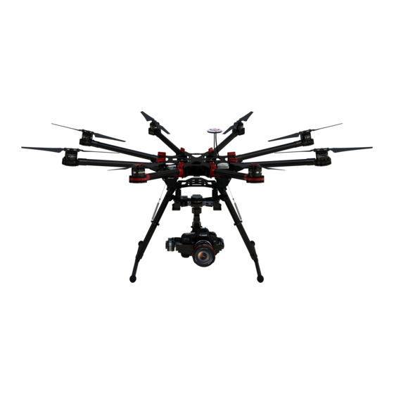
An integrated power hub with patented coaxial connectors, built-in high-speed ESCs and motors with high efficiency propellers ensure dynamic stability and maximized power efficiency. Used with a professional DJI multi-rotor autopilot system, the S1000 can hover and fly reliably making it ideal for photography and cinematography. -
Page 4: Table Of Contents
Remounting the Propeller ..................................25 Propeller Precautions ..................................... 25 Using Propeller Holder ................................... 26 Assembling Motor Vibration Absorbers ............................26 Remounting Landing Gear Servo ............................... 27 Recalibrating Servo Travel ..................................27 Part List ..........................................29 ©2014 DJI. All Rights Reserved. -
Page 5: Caution
Use only 6S LiPo batteries for the power supply. Ensure all output signals from M1 to M8 are in proper working order when using the DJI A2 flight control system to avoid damage or injury. Do not overload the system. -
Page 6: In The Box
2.0mm Hex Wrench, 2.5mm Hex Wrench Mounting screws. Thread Locker Fastening screws. Nylon Cable Tie Binding devices and wires. Scissors Cutting Pliers/Dykes Foam Double Sided Adhesive Tape Mounting receiver, controller and other modules. Hot Air Gun Fixing power cable connectors. ©2014 DJI. All Rights Reserved. -
Page 7: Mounting Landing Gear
Insert the landing gear leg into connection point on the center frame. Affix in place with M3x8 screws. Connect springs to both parts to ensure safety. Complete. Spring length is 58.5mm unstretched and 70mm stretched. 70mm ©2014 DJI. All Rights Reserved. -
Page 8: Mounting Frame Arms
Adjust screw mounts of frame arm and center frame. Insert the M4x35 screw from the right of the frame arm as the thread is located on the left of the screw mount. Tighten screw appropriately. Over tightening may lead to connector abrasion. ©2014 DJI. All Rights Reserved. - Page 9 To store, untwist the knob and lower frame arm. Plug ESC signal cable into center frame. Plug power cable into center frame. Heat-shrinkable tubes can be used to stop the connector from coming off. ©2014 DJI. All Rights Reserved.
- Page 10 Double check all frame arms. Arms M1 and M2 are the forward facing (nose), arms M5 and M6 are the tail. Seen from the top, motors on arms M1, M3, M5 and M7 rotate counter clockwise while those on arms M2, M4, M6 and M8 rotate clockwise. ©2014 DJI. All Rights Reserved.
-
Page 11: Mounting Electronics And Wiring
Eight positions are reserved for mounting a flight control system, wireless video transmission module, receiver, and other items. The DJI A2 flight control system has been used here as an example. If using an A2, follow mounting and wiring instructions found in the A2 flight control system user manual. If using the DJI WK-M flight control system, please refer to the WK-M user manual for connections. - Page 12 Position GPS collapsible mount then return screw to its original position and tighten. Mount a GPS module to the GPS mount with a bracket. Ensure the arrow points toward the nose and avoid catching fingers in the bracket when folding for transportation. ©2014 DJI. All Rights Reserved.
- Page 13 LED flight indicator, iOSD module and wireless video transmission module. Check that every anti-drop system has been firmly installed in the reserved positions. Thread locker is recommended. Remove anti-drop to add appropriate thread locker. Replace and tighten. ©2014 DJI. All Rights Reserved.
- Page 14 Yellow 4-pin cables are for M1~ M4 connections. Yellow cable should be connected to M1. Brown 4-pin cables are for M5~ M8 connections. Brown cable should be connected to M5. Black 4-pin cables are for four continuous ground pins connections. M1~M4 are connected as the following diagram shows. ©2014 DJI. All Rights Reserved.
- Page 15 Notes If using a DJI WK-M flight controller, you must use the wires that came with the WK-M. M1 through M6 correspond to each motor number. M7 corresponds to F1 and M8 corresponds to F2 on the WK-M. Connecting main controller and landing gear Connect left servo cable near M4 to the “RLG”...
- Page 16 Cable of left ser vo Cable of right ser vo Notes If right and left servo cables are reversed, landing gear will not be function. Wire neatly to avoid cables being damaged by frame edges. ©2014 DJI. All Rights Reserved.
-
Page 17: Connecting Xt60 Ports On Center Frame
Connect PMU power cable to XT60 connector on top of the bottom board. Connect landing gear control board cable to XT60 connector on the bottom of the bottom board. Other connectors can supply power for other DJI devices if required. Installing Battery Soldering battery connectors AS150 anti spark connectors are used. - Page 18 Attach battery to battery tray. Do not use an oversized battery. Maximum installation dimension is 80mm X 120mm X 200mm. Insert black connector① then red connector② to power on. Pull out red connector② then black connector① to power off. ©2014 DJI. All Rights Reserved.
-
Page 19: Setting Landing Gear
“Recalibrating Servo Travel”. Toggle switch to [Raise] position ONLY AFTER takeoff. Toggle switch to [Lower] position for landing. Tips Servo power will shut off within 3 seconds after the landing gear has reached its target position. ©2014 DJI. All Rights Reserved. - Page 20 Parameter Range Working Voltage 3S~6S (LiPo) Input Signal PWM (High-Pulse Width 800us~2200us) Working Current Max 1A@6S Output Signal PWM(Mid Position is 1520us) in 90Hz Working Temperature -20~70 Output Voltage Total Weight 875g Servo Travel (Minimum120 ©2014 DJI. All Rights Reserved.
-
Page 21: Mounting The Gimbal
Mounting the Gimbal Before assembling the gimbal, install GCU as shown below. Be sure to install on the side as shown below. A DJI Z15-5D gimbal has been used as an example in the following diagrams. The connectors on gimbal should be removed for better performance, then the gimbal can be mounted to the lower connection points. - Page 22 Check that the system’s center of gravity is at the blue line as shown in the below diagram. ©2014 DJI. All Rights Reserved.
-
Page 23: Appendix
Solid Red or Green On Motor rotating at full throttle position Solid Yellow On Tips: DJI ESCs are specially designed for multi-rotors. When used with DJI autopilot systems parameters and travel ranges do not have to be calibrated. Specifications Frame... -
Page 24: Gain Value Settings (With The A2 Flight Control)
1500W (@9.5Kg Takeoff Weight) Hovering Time 15min (@15000mAh& 9.5Kg Takeoff Weight) Working Environment Temperature C ~ +40 Gain Value Settings (with the A2 flight control) Basic Attitude Pitch Roll Pitch Roll 120% 120% 120% 170% 170% 120% ©2014 DJI. All Rights Reserved. -
Page 25: Faq
Notes: Loose screws cannot be securely locked with thread locker. Propeller Precautions Torque markers on the screws and propeller covers will give you a visual cue to check whether the propellers are loose. Check the torque markers before every flight. ©2014 DJI. All Rights Reserved. -
Page 26: Using Propeller Holder
Assembly is the same for CCW and CW propellers. Notes Ensure all soft dampers and vibration absorbers are in good condition before every flight. If not, replace immediately. Otherwise, the flight performance of your aircraft will be adversely affected. ©2014 DJI. All Rights Reserved. -
Page 27: Remounting Landing Gear Servo
During calibration, the left landing gear will raise and lower, follow by the right landing gear. After calibration, both left and right landing gears will be lowered and the LED will be a solid green. This ©2014 DJI. All Rights Reserved. - Page 28 Avoid obstructions during calibration. If the landing gear was obstructed, recalibration is required using the above steps. If [R] and [L] servo cables are reversed, travel will not be measured correctly. Connect correctly and recalibrate the landing gear using the above steps. ©2014 DJI. All Rights Reserved.
-
Page 29: Part List
S1000-Premium Frame Arm CW – Red S1010701CWR,S1010702,M3x12.3 S1000-Premium Motor Damping Unit S1010801,M3x10.3 S1000-Premium Motor Mount Carbon S1011001,M3x10.3 Board S1000-Premium 4114 Motor with black Prop S1012101B,S1012102B,M3x4.5 cover S1000-Premium 4114 Motor with red Prop S1012201R,S1012202R,M3x4.5 cover S1000-Premium ESC with Red LED S1012301R,S1012302,M3x12.3 ©2014 DJI. All Rights Reserved. - Page 30 Part No. S1000-Premium Lock Knob S1020301,S1020302,M3x8.0 (self-tapping) S1000-Premium Center Frame Support Pillar S1020901,S1020902,M3x4.5,M3x8.0 S1021201L, S1021202R,M3x4.5 ,M3x8.0 , S1000-Premium Arm Mounting Bracket Package 11 S1000-Premium Center Frame Bottom Board S1021401,M3x4.5,M3x8.0 S1000-Premium Center Frame Top Board S1021501,S1021502,M3x4.5,M3x8.0 ©2014 DJI. All Rights Reserved.
- Page 31 S1 0 3 1 8 1 3 and S1 0 3 1 8 1 4 , they are unique to package 1 8 . Package No. Name Part No. S1000-Premium Gimbal Damping Bracket S1031601,S1031602,S1031603,S1031604, S1031605,M2.5 S1000-Premium Retractable Module (Right) S1031701,S1031702,S1031703,S1031704, S1031705,S1031706,S1031707,S1031708, S1031709, S1031710, S1031711, S1031712, M3x4.5 ©2014 DJI. All Rights Reserved.
- Page 32 Package 7,8,10,11,22,23,25,S1012901 [CW-RED] S1000-Premium Complete Arm Package 6,8,10,11,21,24,25,S1013001 [CW-Green] S1000-Premium Complete Arm Package 5,8,10,11,22,23,25,S1013101 [CCW-RED] S1000-Premium Complete Arm Package 4,8,10,11,21,24,25,S1013201 [CCW-Green] S1000-Premium GPS Holder S1032701,S1032702 S1000-Premium Screw Pack Assorted screws S1000-Premium Power Cord Plug S1020201,S1020202,S1020203,S1020204 ©2014 DJI. All Rights Reserved.
Need help?
Do you have a question about the spreading wings s1000 and is the answer not in the manual?
Questions and answers