Table of Contents
Advertisement
Quick Links
Advertisement
Table of Contents

Subscribe to Our Youtube Channel
Related Manuals for Briteq LED EXPO BEAM


Summary of Contents for Briteq LED EXPO BEAM
- Page 1 USER MANUAL Ver 1,0 WWW.BRITEQ-LIGHTING.COM...
-
Page 2: Table Of Contents
ABLE OF CONTENTS PART 1 PRODUCT (GENERAL)............1. 1.1--PRODUCT INTRODUCTION............1. 1.2--PRODUCT FEATURES..............1. 1.3--TECHNICAL SPECIFICATIONS.............2. 1.4--PHOTOMETRIC DATA..............3. 1.5--SAFETY WARNING..............3. PART 2 INSTALLATION...............4. 2.1--MOUNTING...................4. 2.2--POWER CONNECTION..............4. 2.3--SETTING UP WITH A DMX512 CONTROLLER.........5. 2.3-1--DMX512 ADDRESSING WITHOUT ID ADDRESSING........5. 2.3-2--DMX512 ADDRESSING WITH ID ADDRESS..........5. PART 3 DISPLAY PANEL OPERATION.........7. -
Page 3: Part 1 Product (General)
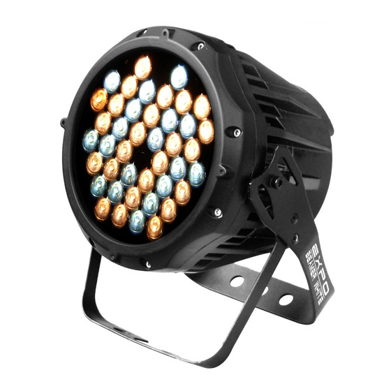
PRODUCT (GENERAL) PRODUCT INTRODUCTION This product is designed for indoor or outdoor use. Suitable applications include wash or effect lighting for architectural, stage or nightclub applications. This product can also be installed for use in signage and advertising using the dynamic functions available with DMX512 control. -
Page 4: Technical Specifications
TECHNICAL SPECIFICATIONS LED MODULE LED MODULE: Voltage 100~240V...50/60Hz Rated Power IP65 protection rating 36pcs (28 x White / 8 x Amber) LED/Unit Output/LED Environment Temperature -20 ~40 Cooling Direct air convection Dimensions 235 x 165 x 300mm Weight 1 PRODUCT(GENERAL) 2008.9.19... -
Page 5: Photometric Data
PHOTOMETRIC DATA WHITE AMBER 2545 741.8 134 LUX 76.5 44.9 31.6 LUX 10Distance(m) 10Distance(m) WHITE+AMBER 3260 163 LUX 10Distance(m) SAFETY WARNING IMPORTANT ALWAYS READ THE USER MANUAL BEFORE OPERATION. PLEASE CONFIRM THAT THE POWER SUPPLY STATED ON THE PRODUCT IS THE SAME AS THE MAINS POWER SUPPLY IN YOUR AREA. -
Page 6: Part 2 Installation
INSTALLATION MOUNTING HANGING The LED PAR can be mounted in a hanging position using the supporting bracket. The bracket should be secured to the mounting truss or structure using a standard mounting clamp. Please note that when hanging the unit a safety cable should also be used. -
Page 7: Setting Up With A Dmx512 Controller
SETTING UP WITH A DMX512 CONTROLLER 2.3-1 DMX512 ADDRESSING WITHOUT ID ADDRESSING (STUDIO 2 MODE) Connect the DMX512 controller to the units in series. Each unit has 6 DMX channels so the DMX Addresses should increase by increments of 6 (e.g. 1,7,13,19...) The ID address has not been set so therefore when using the controller CH8 must be inactive ( CH6=0 ). - Page 8 Example: DMX Addr.1 DMX Addr.1 DMX Addr.1 DMX Addr.7 DMX Addr.7 DMX Addr.7 ID Addr.1 ID Addr.2 ID Addr.3 ID Addr.1 ID Addr.2 ID Addr.3 ... . DMX512 The figure above shows a simple DMX layout CONTROLLER which has used three units at each DMX address.
-
Page 9: Part 3 Display Panel Operation
DISPLAY PANEL OPERATION BASIC The LED fixture is mounted with a LCD display and 4 control buttons. POWER IN POWER OUT DMX IN DMX OUT MENU DOWN MENU DOWN scroll through the main menu or return to the main menu enter the currently selected menu or confirm the current function value scroll 'UP' through the menu list or increase the value of the current function scroll 'DOWN' through the menu list or decrease the value of the current function... -
Page 10: Edit Static Colour
EDIT STATIC COLOUR MODE W.(0~255) S TA I WHIT A.(0~255) S.(0~20) STRb D.(0~255) dIMM STATIC COLOUR Combine White , Amber ,and Dimmer to create whites with different color temperature Set the value of the Strobe (0-20Hz) DMX512 SETTINGS MODE d(001~512) Enter the DMX mode to set the DMX ADDRESS. -
Page 11: Id Address
ID ADDRESS MODE I(001~066) Enter the ID mode to set the ID ADDRESS. SPECIAL SETTINGS MODE UPLd PASS SENd PASS REST REST IdON SETTING Select Upload to upload the custom programs from the current MASTER unit to the SLAVE units. In order to activate the upload function the password must be entered. -
Page 12: Part 4 Using A Dmx512 Controller
USING A DMX512 CONTROLLER BASIC ADDRESSING Connect all of the units in series using standard DMX512 signal cable or the IP65 rated cable provided. Set the DMX512 address in the DMX menu. It is possible to have the same DMX address or independent addresses for each fixture. CHANNEL ASSIGNMENT Note: This product have four DMX512 channel configuration: WA , WA+D... - Page 13 STUDIO 2 CHANNEL VALUE FUNCTION MASTER DIMMER WHITE AMBER DIFFERENT WHITES NO FUNCTION WHITE 1: 2800K WHITE 2: 3000K WHITE 3: 3200K WHITE 4: 3400K WHITE 5: 4200K WHITE 6: 4900K WHITE 7: 5600K WHITE 8: 5900K STROBE NO FUNCTION 1~20Hz ID ADDRESS ID1~ID66...
-
Page 14: Basic Instructions For Dmx512 Operation
BASIC INSTRUCTIONS FOR DMX512 OPERATION (STUDIO 2) MASTER DIMMER CH1 controls the intensity of the currently projected color When the slider is at the highest position (255) the intensity of the output is the maximum WHITE & AMBER SELECTION CH2 and CH3 control the intensity ratio of each of the WHITE & AMBER LEDs. When the slider is at the highest position (255) the intensity of the color is the maximum. -
Page 15: Part 5 Appendix
APPENDIX TROUBLE SHOOTING SITUATION CAUSE ACTION 1) No power input 1) Check power supply 2) Check power connection 2) Power connection error 3) Replace display 3) Display damaged 4) Check the IC and all the connections No display 4) Display board IC error or power input connection error or two board connection error Display normal,... -
Page 16: Maintenance
MAINTENANCE ITEM Gel holder Upper cover Glass plate LED heat-transfer plate Power supply Display board Casing Driver board Secondary support Main support Version 1.0 5 APPENDIX 2008.9.19...
Need help?
Do you have a question about the LED EXPO BEAM and is the answer not in the manual?
Questions and answers