Rinnai RH180 Installation Fundamentals
Hide thumbs
Also See for RH180:
- Operation and installation manual (44 pages) ,
- Technical data sheet (8 pages) ,
- Operation and installation manual (44 pages)

Related Manuals for Rinnai RH180


Summary of Contents for Rinnai RH180
- Page 1 Rinnai RH180 Hybrid Tank – Tankless Water Heater Installation Fundamentals, Level II...
- Page 2 “For Professionals” section of the site under “Partner Portal”. Registration is required for access to this portion of the website. • www.trainingevents.rinnai.us – for registration in Rinnai product training classes and videos (live and online classes). Service and installation manuals and other technical documents are available under the “Resources” section of the site.
- Page 3 RH180 Hybrid Tank-Tankless Water Heater Level II Training Program Installation Fundamentals...
- Page 4 RH180 Technology Combining Technologies: With the combination of a tank and a Rinnai tankless water heater into one appliance, the RH180 hybrid provides increased hot water capacity with the ease of a tank installation.
-
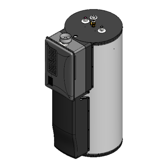
Page 5: Product Component Identification
Product Component Identification • Pressure relief valve • ¾ hot water feed into building • ¾” cold water supply into tank • 4” B-vent exhaust connection • 40 gallon storage tank • Combustion air inlet • 120 Volt power cord and filter (not shown) •... - Page 6 RH180 Sequence of Operation...
-
Page 7: Sequence Of Operation
Sequence of operation: 1. When the water temperature at the bottom of the tank (at the tank thermistor) drops to a pre-determined temperature, the startup sequence will begin. 2. The tankless engine’s combustion fan will begin turning, drawing fresh air from the space. This will allow the flammable vapor sensor to ensure the intake air is free of combustible vapors. - Page 8 RH180 Water Heater Sizing...
- Page 9 • Shower heads assumed to be 2.5 gpm mixed flow rate with 105⁰F at the fixture. • Available hot water time and recovery time based on industry standard calculation methods and Rinnai lab testing. Actual results may vary based on the application.
- Page 10 RH180 Product Features & Safety devices...
-
Page 11: Product Features
Product Features • 180 gallon First Hour Rating. • Quick recovery: Approximately 16 minutes starting from a cold tank. • Thermal Efficiency: 80%. • Temperature controller: 5 temperature settings. • Maintenance/diagnostic codes: Error codes displayed if a fault is detected. •... -
Page 12: Safety Devices
Safety Devices • Flame rod: Detects when flame is present or is extinguished. • Overheat bi-metal sensor: Detects overheated water conditions. • Boiling protection sensor: Monitors heat exchanger water temperature. • Heat exchanger thermal fuse: Detects heat exchanger overheat condition. •... -
Page 13: Specifications
Specifications Model RH180 Min. 59,500 Btu-Natural Gas / 47,600 Btu-Propane Min / Max Gas Input Rates Max. 91,300 Btu-Natural Gas / 87,300 Btu-Propane (two stage burner, does not modulate between max-min inputs) First Hour Rating 180 Gallons / hour Storage Tank Volume 40 gallons 110⁰F, 120⁰F, 130⁰F, 135⁰F, 140⁰F (43⁰C, 49⁰C, 54⁰C, 57⁰C, 60⁰C ) - Page 14 RH180 Installation Requirements A licensed professional must install the appliance, inspect it and leak test it before use. The warranty may be voided due to improper installation. The installer should have skills such as: • Gas sizing • Connecting gas lines, water lines, valves and electricity.
-
Page 15: Installation Location
• Use an approved tank water heater drain pan. (Rinnai recommends 26” diameter pan. See next page for example). See International plumbing code for details. •... -
Page 16: Drain Pan Installation
Drain Pan Installation. Rinnai recommends using a 26” diameter drain pain minimum to provide protection from leaks and still allow removal of the front pipe/pump shroud for service. Use only an approved drain pan and install in accordance with all applicable plumbing and... - Page 17 Installation Location Minimum Clearances: The minimum clearances from both combustibles and non- combustibles construction is: • 0 inches from the sides. • 0 inches from the back. • 12 inches from the top. • 4 inches from the front. NOTE: These clearances are minimums.
- Page 18 Dimensions...
- Page 19 Electrical and Water Installation Code Adherence - Installation MUST comply with National, State, and Local codes. Electrical Requirements Standard three-prong 120 VAC, 60 Hz. grounded circuit. Ensure plumbing lines are grounded in accordance to Local, State, and National codes. Water Installation Requirements - Supply pressure 20 –...
- Page 20 Do not use this appliance in an application such as a pool or spa heater that uses chemically treated water. (the RH180 is suitable for filling large or whirlpool spa tubs using potable water).
-
Page 21: Altitude Requirements
RH180 Venting Altitude Requirements ! WARNING Improper installation of the vent system and its components, or failure to follow all installation instructions, can result in property damage or serious injury... - Page 22 Vent Guidelines: Combustion air Combustion air is drawn from the room in which the water heater is installed. This water heater requires adequate combustion air for ventilation and dilution of flue gasses. Failure to provide adequate combustion air can result in unit failure, fire, explosion, serious bodily injury or death. Read all the venting guidelines in the Operation and Installation manual.
- Page 23 Vent Guidelines: Combustion air Unconfined space: An unconfined space is defined in NFPA 54 as “a space whose volume is not less than 50 cubic feet per 1,000 Btu/hr. (4.8 m per kW per hour) of the aggregate input rating of all appliances in that space. Rooms communicating directly with the space in which the appliances are installed, through openings not furnished with doors, are considered a part of the unconfined space”.
- Page 24 Vent Guidelines: Combustion air Confined and Unconfined space examples: 25 x 25 x 8 = 5000 cubic feet 25 x 25 x 8 = 5000 cubic feet 5000 cubic feet 50 = 100 5000 cubic feet 50 = 100 100 x 1000 = 100,000 Btu 100 x 1000 = 100,000 Btu Unconfined space with a 91,300 Btu water Confined space with 91,300 Btu water...
- Page 25 Vent Guidelines: Combustion air A confined space must have two combustion air openings. Size the combustion air openings based on the Btu input for all gas utilizing equipment in the space and the method by which combustion air is supplied. Louvers and Grills: When sizing the permanent opening: Consideration must be taken for the design of the louvers or grills to maintain the required free area...
- Page 26 Vent Guidelines: Combustion air Using Indoor Air For Combustion: When using air from other room(s) in the building, the total volume of the room(s) must be of adequate volume (Greater than 50 cubic feet per 1,000 Btu/hr.). Each combustion air opening must have at least one square inch of free area for each 1,000 Btu/hr, but not less than 100 square inches each.
- Page 27 Vent Guidelines: Combustion air Using Outdoor Air For Combustion: Outdoor air can be provided to a confined space through two permanent openings, one commencing within 12 inch (300 mm) of the top and one commencing within 12 inches (300 mm) of the bottom, of the confined space.
- Page 28 Vent Guidelines: Combustion air When communicating directly with outdoors through horizontal ducts, each opening shall have a minimum free area of 1 square inch per 2000 Btu/hr (1100 mm /kW) of total input rating of all appliances in the confined space. Note: If ducts are used, the cross sectional area of the duct must be greater than or equal to the required free area of the openings to which they are connected.
- Page 29 Type B double wall vent connectors. For vent passing through an internal wall, use Type B with ventilated thimble ONLY. • The RH180 CANNOT be vented into any chimney serving an open fireplace or any other solid fuel burning appliance.
- Page 30 • Existing exhaust vent or chimney is to be checked to ensure they meet clearances and local codes. • The RH180 can ONLY be connected to a manufactured chimney or vent that complies with a recognized standard. Venting into a masonry or concrete chimney is only permitted as outlined in the NFPA54/ANSI Z223.1 National Fuel Gas Code venting tables.
- Page 31 Vent Guidelines: Exhaust Vent Dampers: Vent dampers must be certified in accordance with ANSI Z21.68. Before installing any flue damper, consult the local gas authority and damper manufacturer for proper installation. Thermal Operated Vent Dampers: Should NOT be used with this appliance. This appliance has a thermal efficiency greater than 80%.
-
Page 32: High Altitude Installations
High Altitude Installations Set dip switch 3 to the position shown in table below for your altitude. The default setting for the appliance is 0 – 2,000 ft. (0 - 610 meters) with dip switch 3 in the OFF position. The maximum allowed altitude for this appliance is 5,400 ft. -
Page 33: Gas Supply Installation
RH180 Gas Supply Installation When sizing a gas system you MUST take into account the type pipe and gas being used, the inlet gas pressure being fed to the site, meter, regulator and/or tank size and Btu ratings. Improperly sized gas system will result in poor performance of all gas appliances. -
Page 34: Gas Installation
The average 40 gallon gas-fired tank water heater has an input rating of approximately 40,000 Btu. In this example, the difference between the RH180 and the 40 gallon tank water heater is 51,300 Btu. This additional gas load must be considered when installing this product. - Page 35 1. Using this method you first pressure, 0.5” w.c. pressure drop, 0.60 specific gravity. Outlet D Outlet C determine the total pipe length from furnace RH180 Pipe Size (in.) 100,000 Btu/hr 91,300 Btu/hr the gas meter to the appliance farthest Nominal: ½...
- Page 36 Outlet D Outlet C Nominal: ½ ¾ 1 ¼ 1 ½ furnace RH180 100,000 Btu/hr 1. Outlet A, section 1, can draw up 91,300 Btu/hr Length Capacity in Cubic Feet of Gas per Hour to 30,000 Btu. This section...
-
Page 37: Gas System
91,300 Btu/hr 100,000 Btu/hr apply high pressure (such as 2 lbs) to a household appliance unless stated by the manufacturer. All Rinnai tankless water heaters Main gas meter Regulators are placed in supplies 2 lbs of close vicinity to all appliances require no more than ½”... - Page 38 RH180 Temperature Controller...
-
Page 39: Temperature Controller
Temperature Controller... - Page 40 Temperature Controller Five temperature settings are available. Push the up and down arrows to select the desired temperature setting. The number on the display corresponds to the temperature scale below. 1. = 110°F 2. = 120°F 3. = 130°F 4. = 135°F 5.
- Page 41 RH180 Maintenance Warranty...
- Page 42 Maintenance – Inlet Water Filter • Rinnai recommends that the inlet water filter be cleaned before the initial operation of a new unit. • Before removing the inlet filter, ensure that the water supply has been turned off. • If the tank is already full, it must be drained from the drain valve at the bottom of the tank.
- Page 43 Maintenance – Intake air filter • The RH180 is a fan assisted water heater. Intake air is drawn into the appliance from the surrounding area. • To maintain optimum performance, periodically clean the air filter. Do not operate unit if the filter is not in place.
- Page 44 Maintenance - Tank • Drain the water from the tank at least once per year. This will remove excess sediment from the bottom of the tank. Accumulated sediment will reduce the efficiency and life expectancy of the tank. • Manually operate the relief valve at least once per year. •...
- Page 45 Maintenance – Engine Heat Exchanger • Flushing the heat exchanger consists of pumping virgin food grade white vinegar or food grade citric acid through the copper heat exchanger to remove lime scale or calcium buildup. • Damage caused by lime or scale buildup is not covered under the water heater’s warranty.
- Page 46 Internal view of tank ¾” cold feed inside tank ¾” anode rod inside tank ¾” circulation pump feed line back into tank Bottom pan of tank...
-
Page 47: Typical Installations
Piping – Typical Installation Hot Water Outlet Combustion Air Screen Typical Installations. Hot water Outlet Valve Operation Unit / Temperature Control Temperature – Pressure Relief valve Outlet Receptacle Cold and Hot Unions Drain Pan Cold Water Supply valve M Temperature – Pressure Relief Valve Discharge Cold Water Supply Pipe (do not cap plug or... - Page 48 Installation Method (2 units) Pictures are for illustration Purposes only. Parallel Piping (recommended method) Hot water out Cold water in Series Piping (not allowed) Drip pans MUST be installed under each water heater per local or State code ,...
-
Page 49: Component Description
Component Description... - Page 50 Component Description...
-
Page 51: Maintenance Codes
Maintenance Codes Maintenance codes flash on the temperature controller when a fault occurs. Depending on the code, water flow or power may need to be reset to clear the code. See owner's manual for a full detailed list of all codes. Diagnostic Codes and Remedies Some of the checks below should be performed by a licensed professional. - Page 52 Maintenance Codes Code Definition Remedy Licensed Air supply or Ensure listed 4” B-vent material is used and there are no reductions in the vent professional cont. exhaust blockage. system. only Check fan for blockage. Ensure vent length, vent size and combustion air comply with the requirements stated in the National Fuel Gas Code, ANSI Z223.1/NFPA 54, or the Natural Gas and Propane Installation Code, CSA B149.1.
- Page 53 Maintenance Codes Code Definition Remedy Licensed No Flame. Ensure gas line, meter, and/or regulator is sized properly. professional cont. Ensure gas type and pressure is correct. only Bleed air from the gas lines. Ensure vent length, vent size and combustion air comply with the requirements stated in the National Fuel Gas Code, ANSI Z223.1/NFPA 54, or the Natural Gas and Propane Installation Code, CSA B149.1.
- Page 54 Maintenance Codes Code Definition Remedy Flammable Vapors When safety personnel have identified the area as safe and all flammable Cont. Detected. vapors have been removed and eliminated, the water heater can be reset by unplugging the unit and then plugging back in. If “FE”...
- Page 55 Maintenance Codes Code Definition Remedy Over temperature Check for restrictions in air flow around the unit and vent termination. warning (safety Licensed Check for foreign materials in combustion chamber and/or exhaust piping. shutdown because professional Check for clogged heat exchanger. unit is too hot).
- Page 56 Maintenance Codes Code Definition Remedy Licensed CO or FV sensor. Check sensor wiring for damage. professional Measure resistance of sensor. only Replace sensor. Licensed Modulating Check modulating gas solenoid valve wiring harness for loose or damaged professional solenoid valve terminals. only signal.
- Page 57 Maintenance Codes Code Definition Remedy Licensed Flame sensing Verify flame rod is touching flame when it fires. professional device. Check all wiring to flame rod. only Remove flame rod and check for carbon buildup. Check inside burner chamber for any foreign material blocking flame at flame rod.
- Page 58 Maintenance Codes – No Code displayed. Further explanation of conditions that might cause no hot water and/or No error codes: Since the hot water supply to the building comes from the tank and not directly from the tankless engine, opening a fixture will not flow water through the engine and will not automatically trigger it to fire.
-
Page 59: Wiring Diagram
Wiring Diagram The Technical Data Booklet that is included with the water heater contains specific information for diagnostic service points, voltage and resistance readings. Layout of wiring and connection points on the wiring diagram correspond directly to the location of these points on the PCB. -
Page 60: Warranty
Warranty How long does warranty coverage last? Period of coverage (from date of purchase) Item Single family Residential Commercial applications Combination domestic hot water / space applications. Domestic hot water only heating and all other applications. [3] Heat Exchanger 10 years [1] 5 years [2] 3 years Tank... - Page 61 RH180...
- Page 62 Is the engine available separately? • No, because the minimum input is 60,000 Btu, ignition occurs at no less than 2 gpm-this is not a viable stand alone tankless product. Is this product ENERGY STAR rated? • No, currently there is no qualification for tank water heaters over 75,000 Btu. What is the energy factor rating? •...
- Page 63 Yes. No additional equipment (such as MSA control accessories) is required. They should be installed with balanced parallel piping. 13. What are the makeup air requirements of the RH180? • Please see the installation manual for the appropriate room calculation procedures to determine this.
- Page 64 RH180 Residential Applications...
- Page 65 Three, 40 gallon tank water heaters (2-gas, 1-electric) servicing a 5,000 sq. ft. home The gas units were common vented with a furnace. No change to the existing vent was required to install the RH180. The RH180 sufficiently replaced all three tanks.
- Page 66 Before / After Installations Before After 40 gallon gas tank water heater common vented with existing furnace. No change to existing vent was required beyond junction point.
- Page 67 Before / After Installations Before After No change to existing vent beyond junction point. 40 gallon gas tank water heater common vented with furnace.
- Page 68 Before / After Installations Before After 40 gallon gas natural tank. Venting was changed to 4” using the same roof flashing and penetration...
- Page 69 Before / After Installations Before After Two 40 gallon tank water heaters replaced with one RH180, freeing up valuable storage space...
-
Page 70: Installation Fundamentals
This concludes the RH180 Water Heater Training Program Level II Installation Fundamentals 401102 (12/2013)
Need help?
Do you have a question about the RH180 and is the answer not in the manual?
Questions and answers