Rinnai RH180 Technical Data Sheet
Hybrid tank-tankless water heater
Hide thumbs
Also See for RH180:
- Installation fundamentals (70 pages) ,
- Operation and installation manual (44 pages) ,
- Operation and installation manual (90 pages)
Table of Contents
Advertisement
Quick Links
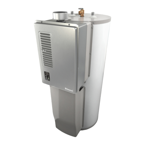
Hybrid Tank-Tankless Water Heater
Temperature
Display
Indicates
temperature
setting or flashes
error code.
Temperature
Selector
Gas Pressure Setting
NOTE: For additional installation and commissioning information
In Use Indicator
refer to the Operation and Installation Manual.
Indicates the
water heater is in
a recovery mode.
This appliance must be installed, serviced and removed by a
trained and qualified person. During pressure testing of the
consumer piping, ensure gas valve is turned off before unit is shut
off. Failure to do so may result in serious injury to yourself or
damage to the unit.
ON / OFF
APPLIANCE OPERATING PRESSURES
Button
Water Inlet Max is 150 PSI
Gas Inlet Min/Max
Nat. G.
4" W.C. /
10.5" W.C.
Ensure gas pressure check under Commissioning has been
completed first! The regulator is electronically controlled and
factory pre-set. Under normal circumstances it does not require
adjustment during installation. Make adjustments only if the unit is
not operating correctly and all other possible causes for incorrect
operation have been eliminated.
1. Turn OFF the gas supply.
2. Turn OFF the 120 V power supply.
3. Remove the front panel from the appliance.
4. Check the gas type using the data plate on the side of the unit.
If using a spare PC board, check that the gas type switches are
in the correct position (dip switch 1: ON for natural gas, NG, and
OFF for propane, LPG). See dip switch settings section below. (ON
is towards the right and OFF is towards the left.)
5. Attach the pressure gauge to the burner test point, located on
the gas control (Fig. 2).
6. Turn ON the gas supply.
7. Turn ON the 120 V power supply.
8. Turn the unit ON with the controller. Select the maximum delivery
temperature and open an available hot water fixture. Leave the
fixture on until all gas pressure setting is complete
9. When the red "In Use" light turns on, set the unit to "Forced Low"
combustion by setting No. 7 dip switch to ON (Fig. 3).
10. Check the burner test point pressure.
11. Remove the rubber access plug and adjust the regulator screw
on the modulating valve (Fig. 4) as required in Table 1. Replace the
rubber access plug.
12. Set the unit to "Forced High" combustion by setting both No. 7
and No. 8 dip switches to ON (Fig. 5). Ensure maximum water flow.
13. Check the burner test point pressure.
14. Adjust the high pressure potentiometer (POT) on the PC board
as required to the pressure shown in Table 1.
15. Return the unit to normal operation by setting dip switches 7
and 8 back to OFF (Fig. 6). Close all water taps.
16. Turn OFF the gas supply and 120 V power supply.
17. Remove the pressure gauge and install sealing screw.
18. Turn ON the gas supply and 120 V power supply.
19. Operate the unit and check for gas leaks at the test point.
20. Install the front panel.
NOTE: For additional installation and commissioning information
refer to the Operation and Installation Manual.
Commissioning
With all gas appliances in operation at maximum gas rate, the
flowing inlet pressure at the incoming test point on the Rinnai
water heater should read 4" W.C. - 10.5" W.C. on natural gas
and 8" W.C. - 13.5" W.C. on propane gas. If the pressure is
lower, the gas supply is inadequate and the unit will not operate
to specification. Check the gas meter regulator and pipework for
correct operation/sizing and correct as required.
RH180 (REU-VA1320WF-US)
Technical Data Sheet
Forced Low
LPG
Nat. G.
LPG
8" W.C. /
13.5" W.C. 1.10" W.C. 1.23" W.C. 2.8" W.C. 3.0"
Table 1
Forced High
Nat. G.
LPG
W
.
C
Advertisement
Table of Contents

Related Manuals for Rinnai RH180


Summary of Contents for Rinnai RH180
-
Page 1: Gas Pressure Setting
Commissioning With all gas appliances in operation at maximum gas rate, the flowing inlet pressure at the incoming test point on the Rinnai water heater should read 4" W.C. - 10.5" W.C. on natural gas and 8" W.C. - 13.5" W.C. on propane gas. If the pressure is lower, the gas supply is inadequate and the unit will not operate to specification. - Page 2 TROUBLESHOOTING Important Safety Notes Thermistors: There are a number of (live) tests that are required when fault Check all thermistors by inserting meter leads into each end finding this product. Extreme care should be used at all times of the thermistor plug. Set your meter to the 20 K scale and to avoid contact with energized components inside the water read resistance.
-
Page 3: Wire Diagram
WIRE DIAGRAM COLOR CODING W :White WATER FLOW BK:Black SENSOR BR:Brown CO SENSOR R :Red BL:Blue Y :Yellow R Y BK P :Pink O :Orange GY:Gray PU:Purple TANK THERMISTOR MODUL ATING VALVE CURRENT ADJUSTING OUTGOING THERMISTOR Dip SW1 Gas type BURNER THERMISTOR Gas pressure Setting OPERATION... - Page 4 05 Air Filter Error 14 Thermal Fuse Follow the procedure in the “Air Screen” section of the owner’s manual. Check gas type of unit and ensure it matches gas type being used. If the error code continues to flash after cleaning the air filter, review Check for restrictions in air flow around unit and vent terminal.
Need help?
Do you have a question about the RH180 and is the answer not in the manual?
Questions and answers