Table of Contents
Advertisement
Quick Links
Advertisement
Table of Contents

Related Manuals for VARIZOOM Cinema Pro JR


Summary of Contents for VARIZOOM Cinema Pro JR
- Page 1 Cinema Pro JR Operations Manual - 1 -...
- Page 2 BEFORE YOU START, READ THESE WARNINGS 1) NEVER PLUG POWER DEVICES OTHER THAN THOSE SUPPLIED BY VARIZOOM INTO THE SYSTEM. ONLY USE VARIZOOM POWER SOURCES AND CABLES. USING DIFFERENT POWER COMPONENTS CAN LEAD TO SEVERE DAMAGE TO THE HEAD AND EVEN THE CAMERA.
-
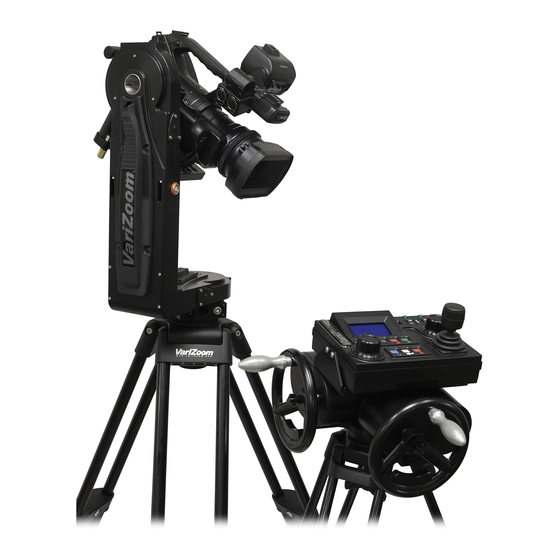
Page 3: General Description
PC data share, and additional recorded takes and mark points. The Cinema Pro JR Advanced Controller gives the user all input and programming capabilities and has a joystick for pan & tilt control. The Advanced Controller also works in concert with two optional control input devices: Pan Bars for broadcast-style operation or Hand Wheels for cinema- style operation. - Page 4 The upper right portion of the LCD screen shows motor status and current positions for pan, tilt, zoom and focus. A check in the box to the left of the axis name indicates that that motor is enabled to run. If soft limits are enabled for the axis, the box is filled and appears white with a blue check mark.
- Page 5 The “cancel” button is used to cancel the last item changed, or to back out of a sub menu. Pressing “cancel” twice will always return to the main screen. The “Q” button is basically a shift key, and is used to change the function of other buttons.
- Page 6 Feeding External Cables through the Head In some cases, you will need to feed video or other cables through the head. To do so, simply remove the cable covers (pictured at right, covers may differ slightly in appearance). 4 screws secure the long vertical cable cover, while only 2 screws secure the short horizontal cover.
- Page 7 To get the vertical balance right, raise or lower the platform to get the camera’s vertical center of mass located on the center of tilt rotation. To adjust, loosen the platform locking lever about ½ turn. Turn the brass knob on the underside of the platform to precisely raise or lower it.
- Page 8 - This only needs to be changed if you are using camera lens controls other than the VariZoom TOC system. In other words, if you’re connecting directly to a Canon or Fujinon lens servo, or even a Preston system, you’ll need to go into this menu to set things up properly.
- Page 9 Canon or Fujinon Digital Servos If you are using a Canon or Fujinon lens with digital servos, press “enter” until the lens manufacturer’s name appears. Digital servos should automatically work with no setup. Head Setup – You only need to enter this menu to switch the head between wired and wireless mode.
- Page 10 Speed adjustment Basic speed adjustment for pan and tilt can be made in the main menu screen. Move the cursor box to “spd” using the setup knob, and press “enter”. The setup knob will then change the speed for both pan and tilt (the number shown in the box is a percentage of the advanced speed setting).
- Page 11 camera down. If it is changed to – turning the encoded wheel clockwise will tilt the camera down, and pressing the joystick forward will tilt the camera up. Direction- Out will change the direction in which the head sends the signal back to the controller.
- Page 12 6. Setting Zero You can custom set the axis position indicator to read zero wherever is necessary. Move each axis to your desired zero point**. From the main screen select the “set” option. Then a sup menu will appear to the right. Select the “zero”...
- Page 13 Now move the cursor box to “Disabled”, and press “enter” The box now shows “enabled”, and your soft limits are set that that particular axis. Note: If the system is set up to be in “one-way” mode, you can quickly enable or disable pan and tilt soft limits from the main screen.
- Page 14 Once you choose where you want to store the mark, press “enter” Move the axes to the position that you wish them to set for this mark position. Select the “set” option. From the sub menu select “Mark” This will then record all current axes positions to the mark displayed in the upper left. Recalling Marks To recall a mark position, select the “Mark”...
- Page 15 From here, you can select the take where you want to store your move. The bottom left will display how long the existing take is (if it is empty it will display “0”), and how many seconds are available for recording in the system’s memory. Press the “record”...
- Page 16 Note: When selecting a take for playback, or recording, hold the “stop” button while turning the setup knob. This will skip to the next take that has a move recorded. I.E. if you have a move recorded on take 2, and a move recorded on take 12, and moves 3-11 are blank, this will scroll the numbers directly from take 2 to take 12.
- Page 17 Select “Jog Time” from the setup menu Under the “jog time” option, you can set the number of seconds the Head will take to go from mark to mark, from zero to mark, or from mark to zero. Under “jog motion” you can choose either “s-curve” or “linear”. This is how the speed will vary throughout the motion.
- Page 18 When 0 is selected, zoom will not affect the pan and tilt axes. Note: This is only accurate when using the Varizoom TOC system, Preston MDR2, Canon lens with digital servos, or Fujinon lens with digital servos. If you are using a Canon or Fujinon lens with Analog Servos, the zoom positions will not be accurate, and with feature will not function properly.
- Page 19 16. System resets The “reset all” option is found in the second setup menu screen. When selected this will reset all parameters only. All stored marks, and takes will not be effected. To reset all motor parameters only, turn the console power off Hold the “cancel”...
- Page 20 Head Power Requirements: 24 VDC regulated, 120 watts max WARNING: Do not connect the head to any power supply other than the one supplied. If you must power the head another way, make sure you clear it with VariZoom first. Connectors Head Base connectors...
- Page 21 Jib Counterweight Option Some lightweight jibs may not have enough mass to neutralize the high acceleration and torque of the CP Jr head. If the motion of the head causes your jib to sway from side to side in a way you want to eliminate, we have a counterweight option that will effectively eliminate the problem.
- Page 22 Appendix 24VDC Power Supply Connector 1) Power Supply Connector – XLR 4-pin Female Function Wire Color N.C. CP JR Neg. Black & Green CP JR Pos. White & Red N.C. * 2) Optional XLR Y-adapter for running head AND camera power through single XLR extension Y-1 “Camera”...
- Page 23 YOUR CAMERA IF YOU USE A NON-APPROVED POWER SUPPLY. IF YOU MUST POWER IT USING A BATTERY SYSTEM, MAKE SURE THE SETUP IS APPROVED BY VARIZOOM AND EXECUTED BY A QUALIFIED TECHNICIAN. CP JR Head - Top Connectors 1) Camera Power (Red) – LEMO EGG2B302CLL...
- Page 24 2) Lens Control (Orange) – LEMO EGG2B316CLL (Final Version) Function Lens Connection RS-232 RXD Fuji Digital RS-232 TXD Fuji Digital +5 VDC – Iso Fuji Digital Common – Iso Fuji Digital RS-422 RXD Canon Digital RS-422 RXD! Canon Digital RS-422 TXD Canon Digital RS-422 TXD! Canon Digital...
- Page 25 Advanced Controller Connectors (if applicable) 1) Auxiliary power input Center 18 to 36 volts input Common 2) “CTRL” - Head Control (Green) – LEMO EGG1B307CLL Function Wire Color (Cable) Common Brown RS-422 RXD RS-422 RXD! Orange RS-422 TXD Yellow RS-422 TXD! Green 24 VDC + Blue...
- Page 26 4) “WHEELS” - Wheels and Panbars Option Input (Blue) – EGG1B306CLL Common +5 VDC Pan encoder signal “A” Pan encoder signal “B” Tilt encoder signal “A” Tilt encoder signal “B” 5) “BLOOP” - Sync & Bloop – Fischer D103A056-130 Common – Isolated +5 VDC –...
Need help?
Do you have a question about the Cinema Pro JR and is the answer not in the manual?
Questions and answers