Table of Contents
Advertisement
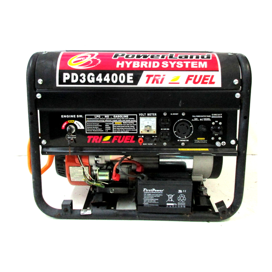
Owner's Manual
Full Power Output Panel
SERIES GASOLINE, LPG, NG POWER
This manual provides information regarding the operation and maintenance of these
products. We have made every effort to ensure the accuracy of the information in this manual.
We reserve the right to change this product at any time without prior notice.
Please keep this manual available to all users during the entire life of the GASOLINE, LPG,
NG generator.
Advertisement
Table of Contents


Need help?
Do you have a question about the PD3G4400E and is the answer not in the manual?
Questions and answers
Unable to start engine on ng. Will start fine on gasoline . Whjen used engine ran fine. It has been a year since we have operated.