Table of Contents
Advertisement
Advertisement
Table of Contents

Subscribe to Our Youtube Channel
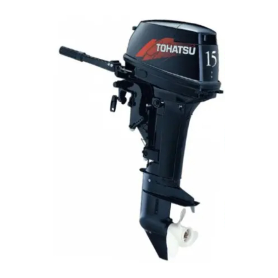
Related Manuals for TOHATSU M 9.9


Summary of Contents for TOHATSU M 9.9
- Page 1 OWNER’S MANUAL M 9.9 OB No.003-11049-A...
- Page 2 INJURY OR DEATH. KEEP THIS MANUAL IN A SAFE LOCATION FOR FUTURE REFERENCE. Copyright © 2011 Tohatsu Corporation. All rights reserved. No part of this manual may be reproduced or transmitted in any from or by any means without the express written...
- Page 3 WILL NOT BE COVERED BY THE APPLICABLE LIMITED WARRANTY, IF THIS PROCEDURE IS NOT FOLLOWED. PRE-DELIVERY CHECK Be sure that the product has been checked by an authorized TOHATSU dealer before you take delivery. Limited Warranty Please refer to the TOHATSU outboard motor Limited warranty provided to you with this product, the terms and conditions of which, as amended from time to time, are incorporated by reference into the manual.
- Page 4 Serial Number : To You, Our Customer Thank you for selecting a TOHATSU outboard motor. You are now the proud owner of an excellent outboard motor that will service you for many years to come. This manual should be read in its entirety and the inspection and maintenance procedures described later in this manual should be followed carefully.
-
Page 5: Table Of Contents
CONTENTS GENERAL SAFETY INFORMATION ........8 SPECIFICATIONS . - Page 7 INDEX GENERAL SAFETY INFORMATION 1. SPECIFICATIONS 2. NAMES OF PARTS 3. INSTALLATION 4.PRE-OPERATING PREPARATIONS 5.ENGINE OPERATION 6.REMOVING AND CARRYING THE OUTBOARD MOTOR 7.TRAILERING 8.ADJUSTMENT 9.INSPECTION AND MAINTENANCE 10.TROUBLESHOOTING 11.TOOL KIT AND SPARE PARTS 12.OPTIONAL ACCESSORIES 13.PROPELLER TABLE...
-
Page 8: General Safety Information
GENERAL SAFETY INFORMATION NOTICE : DANGER/WARNING/CAUTION/Note Before installing, operating or otherwise handling your outboard motor, be sure to thoroughly read and understand this Owner's Manual and carefully follow all of the instructions. Of particular importance is information preceded by the words "DANGER,"... - Page 9 SAFE OPERATION OF BOAT As the operator/driver of the boat, you are responsible for the safety of those aboard and those in other boat around yours, and for following local boating regulations. You should be thoroughly knowledgeable on how to correctly operate the boat, outboard motor, and accessories.
-
Page 10: Specifications
SPECIFICATIONS 9.9D2, 9.9D2 EF, 9.9D2 EP MODEL 9.9D2 9.9D2 EF 9.9D2 EP Item Overall Length mm (in) 869 (34.2) 565 (22.2) Overall Width mm (in) 345 (13.6) 290 (11.4) 1,067 (42.0) · 1,194 (47.0) · 1,321 (52.0) Overall Height S·L·UL mm (in) 435 (17.1) ·... - Page 11 SPECIFICATIONS 15D2, 15D2 EF, 15D2 EP MODEL 15D2 15D2 EF 15D2 EP Item Overall Length mm (in) 869 (34.2) 565 (22.2) Overall Width mm (in) 345 (13.6) 290 (11.4) 1,067 (42.0) · 1,194 (47.0) · 1,321 (52.0) Overall Height S·L·UL mm (in) 435 (17.1) ·...
- Page 12 SPECIFICATIONS 18E2, 18E2 EF, 18E2 EP MODEL 18E2 18E2 EF 18E2 EP Item Overall Length mm (in) 869 (34.2) 565 (2.22) Overall Width mm (in) 345 (13.6) 290 (11.4) 1,067 (42.0) · 1,194 (47.0) · 1,321 (52.0) Overall Height S·L·UL mm (in) 435 (17.1) ·...
-
Page 13: Names Of Parts
NAMES OF PARTS 9.9D2, 15D2, 18E2 Tilt Handle Starter Handle Fuel Connector (Male) Top Cowl Shift Lever Oil Plug (Upper) Bottom Cowl Throttle Grip Water Plug Reverse Lock Lever Adjust Nut Oil Plug (Lower) Cooling Water Check Port Clamp Screw Primer Bulb Drive Shaft Housing Clamp Bracket... - Page 14 NAMES OF PARTS 9.9D2 EF, 15D2 EF, 18E2 EF Tilt Handle Shift Lever Fuel Connector (Male) Top Cowl Throttle Grip Oil Plug (Upper) Bottom Cowl Adjust Nut Water Plug Reverse Lock Lever Clamp Screw Oil Plug (Lower) Cooling Water Check Port Clamp Bracket Primer Bulb Drive Shaft Housing...
- Page 15 NAMES OF PARTS 9.9D2 EP, 15D2 EP, 18E2 EP Tilt Handle Shift Lever Stop Switch Top Cowl Clamp Screw Cord Assembly Bottom Cowl Clamp Bracket Oil Plug (Upper) Reverse Lock Lever Thrust Rod Water Plug Cooling Water Check Port Water Inlet Oil Plug (Lower) Drive Shaft Housing Stop Switch...
-
Page 16: Installation
INSTALLATION Transom matching 1. Mounting the outboard motor on boat 1 Be sure that the anti ventilation plate of the outboard motor is 30-50mm ������� (1.2-2 in) below the bottom of hull. If the above condition cannot be Most boats are rated and certified met due to the shape of the bottom in terms of their maximum allowable of your boat, please consult your... - Page 17 INSTALLATION ������� ������� • Before beginning the running test, • Mounting the outboard motor without check that the boat with maximum following this manual can lead to capacity loading floats on the unsafe conditions such as poor water in a proper attitude. Check maneuverability, lack of control or the position of water surface on fire.
-
Page 18: Installing The Remote Control Devices
Assembly (Wiring Harness) : Spring pin Shift cable ������� ������� When using other than Tohatsu’s genuine Be careful not to loop the remote remote control box, DO NOT select the control cables to a diameter of 406 one without neutral safety switch that mm (16 inches) or less. - Page 19 INSTALLATION 2 Fitting of Remote Control Cable to Engine Throttle side..Set the throttle cable to the cable clip and then connect the holder cap to the ball joint of advancer arm. Shift side..Set the shift cable to the cable clip and then insert the lock pin at the shift lever fitting hole and turn it 90°...
- Page 20 INSTALLATION 3 Connecting the Cord Assembly (Wiring Harness) Pass the cord assembly from the remote control through the hole in the lower cowl and connect the electric terminals and then clamp the cord assembly according to the drawing below. Choke solenoid Blue Blue Rectifier...
-
Page 21: Installing The Battery
INSTALLATION 3. Installing the battery ������� Battery generates explosive hydrogen 1 Place the battery box in a convenient gas. Be sure to: position away from possible water • Charge the battery in a well- spray. Securely fasten both the box ventilated place. - Page 22 INSTALLATION 2 Connect the positive lead (+) to the positive terminal (+) of the battery, and then connect the negative lead (−). When disconnecting the battery always remove the negative lead (−) first. After connecting the positive terminal (+), securely place a cap on it to prevent short circuits.
-
Page 23: Pre-Operating Preparations
PRE-OPERATING PREPARATIONS ������ 1. Recommended gasoline types Consult an authorized dealer for details ������� on handling of gasoline, if necessary. Gasoline and its vapors are very Use of low-quality gasoline results in flammable and can be explosive. a short engine life as well as starting difficulties and other engine problems. - Page 24 ������� TOHATSU recommend the use of Do not fill the fuel tank over capacity. The gasoline if its ethanol content is less rise of gasoline temperature may cause than 10% or methanol content is less gasoline to expand which, if overfilled, may...
-
Page 25: Recommended Engine Oil
PRE-OPERATING PREPARATIONS Note 2. Recommended engine oil Use of engine oils that do not meet U s e a g e n u i n e e n g i n e o i l o r these requirements will result in reduced recommended one. - Page 26 PRE-OPERATING PREPARATIONS Engine oil – gasoline mixing procedure For quantities of engine oil and gasoline to be pre-mixed, refer to table in previous page. ������� ● Do not use other than two stroke engine oil with specified grade, or the engine may be damaged. ●...
-
Page 27: Break-In
PRE-OPERATING PREPARATIONS 3. Break-in Your new outboard motor and lower ������� unit require break-in for the moving c o m p o n e n t s a c c o r d i n g t o t h e Operating the outboard motor without conditions described in the following break-in can shorten service life of the... -
Page 28: Engine Operation
ENGINE OPERATION 2 Attach the fuel connector to the 1. Starting engine connector. The arrow mark on the primer bulb ������� should be facing the engine. In case engine starts in gear, do not start cruising. Stop engine immediately Stop switch and consult an authorized dealer. - Page 29 ENGINE OPERATION 5 Turn the throttle grip until the mark ■ 9.9D2, 15D2 and 18E2 type 4 Place the shift lever in the Neutral on the grip faces the triagular mark on the steering handle. position. Be sure that the shift is in Neutral when 6 Pull out the choke knob all the way.
- Page 30 ENGINE OPERATION ■ EF type ■ EP type 7 Push the starter button. 4 Insert the main switch key. 5 Set the control lever in the Neutral 8 Release pushing the button when position. the engine has started. Neutral (N) Starter button Fully open Control...
- Page 31 ENGINE OPERATION 9 Returns the Free accel lever to close If the recoil starter fails to operate position. • Remove the top cowl and the recoil starter. Wrap a rope around the starter pulley then pull quickly to start. Lock button •...
-
Page 32: Warming Up The Engine
ENGINE OPERATION ■ Engine speed 2. Warming up the engine Idling speed after warming up. Warm the engine at low engine speeds Clutch in (In gear) Clutch off (Out of gear) for about three minutes. This allows the 800 rpm 950 rpm lubricating oil to circulate to all parts of the engine. -
Page 33: Forward And Reverse
ENGINE OPERATION 3. Forward and reverse ■ 9.9D2, 15D2, 18E2 and EF type ������� Before shifting into forward or reverse, Reverse Forward make sure that boat is properly moored Shift lever and outboard motor can be steered fully to the right and left. Make sure that no swimmer(s) is ahead or astern of the boat. - Page 34 ENGINE OPERATION EP type ������� Control lever Be sure to warm up engine well before starting cruise. Operating cold engine may cause damage to your motor. Lock button Note Neutral Idle speed may be higher during warming up of engine. If shifted to Forward or Reverse during warming up, it may be difficult to shift back to neutral.
-
Page 35: Stopping
ENGINE OPERATION EP type 4. Stopping 9.9D2, 15D2, 18E2 and EF type Stop switch Stop switch lock Hook Stop switch lock 1 Turn the throttle grip to the slow position. 2 Put the shift lever in the Neutral position. Run the engine for 2-3 minutes at idling speed if it has been running at full speed. -
Page 36: Trim Angle
ENGINE OPERATION 5. Trim angle The trim angle of the outboard motor can be adjusted to suit the transom angle of the hull, and load conditions. Choose an appropriate trim angle that will allow the anti ventilation plate to run parallel to the water surface during Thrust rod operation. -
Page 37: Tilt Up, Tilt Down And Shallow Water Operation
ENGINE OPERATION ������� 6. Tilt up, tilt down and shallow water operation • Do not put hand or finger in ������� between outboard motor body and clamp bracket when adjusting trim When tilting up or down, be careful not angle to prevent injury in case the to place your hand between the swivel outboard motor body falls. - Page 38 ENGINE OPERATION 1 Shallow water running position: ■ Shallow water operation Put the reverse lock lever in the tilt ������� up position, and tilt up the outboard motor to put the outboard motor in During shallow water operation, be the shallow water running position. careful not to place your hand between the swivel bracket and the stern Reverse lock lever...
- Page 39 ENGINE OPERATION ������� Do not tilt up outboard motor while engine operates, or no cooling water may be fed, leading to engine seizure due to overheating. Sub water inlet ������� Do not overtilt outboard motor when driving shallow water, or air may be sucked through subwater inlet, potentially leading to engine overheating.
-
Page 40: Removing And Carrying The Outboard Motor
REMOVING AND CARRYING THE OUTBOARD MOTOR 1. Removing the outboard motor 3. Storing the outboard motor 1 Stop the engine. Outboard motor should be stored in a 2 Disconnect the fuel connector, vertical position. the remote control cables and the battery cords from the outboard Note motor. -
Page 41: Trailering
TRAILERING ������� ������� Do not go under outboard motor tilted When trailering the outboard motor up even if it is supported by support should be in a vertical (normal running) bar, or accidental fall of outboard motor position, fully down. Trailering in the could lead to severe personal injury. -
Page 42: Adjustment
ADJUSTMENT 1. Steering friction 2. Remote control lever load The steering friction can be adjusted (Throttle friction adjustment screw) in accordance with your preference by To adjust the load of the remote turning the steering adjusting bolt. control lever, turn the throttle friction adjustment screw on the front of the remote control. -
Page 43: Trim Tab Adjustment
ADJUSTMENT ������� 3. Trim tab adjustment • Inappropriate adjustment of trim If straight-line cruising can not be tab could cause steering difficulty. achieved, adjust the trim tab located After installing or readjusting trim under the anti ventilation plate. tab, check if steering load is even. •... -
Page 44: Inspection And Maintenance
INSPECTION AND MAINTENANCE Care of your outboard motor To keep your outboard motor in the best operating condition, it is very important that you perform daily and periodic maintenance as suggested in the maintenance schedules that follow. ������� • Your personal safety and that of your passengers depends on how well you maintain your outboard motor. -
Page 45: Daily Inspection
INSPECTION AND MAINTENANCE 1. Daily inspection Perform the following checks before ������� and after use. Do not use outboard motor on which any abnormality is found during pre-operation check or it could go into trouble during cruising potentially leading to accident. Item Points to Check Action... - Page 46 INSPECTION AND MAINTENANCE Washing outboard motor ■ Use flushing plug. If outboard motor is used in salt water, 1 Remove propeller (refer to Propeller brackish water or water with a high Replacement). Remove the water acidic level, use fresh water to remove plug from the outboard motor, and salt, chemicals or mud from exterior screw in the flushing plug.
- Page 47 INSPECTION AND MAINTENANCE Replacing the propeller ������� A worn-out or bent propeller will lower the motor's performance, and cause Do not hold propeller with hand(s) when loosening or tightening propeller engine trouble. nut. Put a piece of wood block Before removing the propeller, remove between propeller blade and anti the spark plug caps from the spark ventilation plate to hold propeller.
- Page 48 INSPECTION AND MAINTENANCE Replacing the spark plugs Note ������� • Spark plug torque : 18.0 Nm (13.3 ft-lb) (1.8 kgf-m) • Do not reuse spark plug with damaged If a torque-wrench is not available insulation, or sparks can leak through when you are fitting a spark plug, a crack, potentially leading to electric good estimate of the correct torque is...
-
Page 49: Periodic Inspection
INSPECTION AND MAINTENANCE 2. Periodic inspection It is important to inspect and maintain your outboard motor regularly. At each interval on the chart below, be sure to perform the indicated servicing. Maintenance intervals should be determined according to the number of hours or number of months, whichever comes first. - Page 50 INSPECTION AND MAINTENANCE Cleaning the fuel filters and the ■ Fuel filter (for fuel tank) fuel tank Remove the fuel pickup elbow of the Fuel filters are provided inside the fuel fuel tank by turning it counterclockwise tank and engine. and clean the fuel filter.
- Page 51 INSPECTION AND MAINTENANCE Replacing gear oil ������� Upper oil plug hole • Be sure that outboard motor is secured to transom or service stand, or accidental drop or fall of outboard motor could lead to severe personal injury. • Be sure to lock outboard motor if it is tilted up, or accidental fall of outboard motor could lead to severe personal injury.
-
Page 52: Off-Season Storage
INSPECTION AND MAINTENANCE 3. Off-season storage over several times while feeding the oil into it and make sure it is evenly Before you put your outboard motor distributed. in storage, it is a good opportunity to 5 Change the gear oil in the gear have it serviced and prepared by your case. -
Page 53: Pre-Season Check
INSPECTION AND MAINTENANCE 4. Pre-season check Specific Terminal Charge Gravity at 20 °C Voltage (V) Condition 1 Check that the shift and throttle Fully 1.120 10.5 discharged function properly. (Be sure to turn the propeller shaft 1.160 11.1 1/4 charged when checking the shift function or else 1.210 11.7... -
Page 54: Motor Submerged In Water
INSPECTION AND MAINTENANCE 5. Motor submerged in water 6. Cold weather precautions After taking your outboard motor out of If you moor your boat in cold weather the water, immediately take it to your at temperatures below 0˚C (32˚F), dealer. there is the danger of water freezing The following are the emergency in the cooling water pump, which may... -
Page 55: Checking After Striking Underwater Object
INSPECTION AND MAINTENANCE 7. Checking after striking underwater object S t r i k i n g t h e s e a b o t t o m o r a n u n d e r w a t e r o b j e c t m a y s e v e r e l y d a m a g e t h e o u t b o a r d m o t o r . -
Page 56: Troubleshooting
TROUBLESHOOTING If you encounter a problem, consult the check list below to determine the cause and to take the proper action. An authorized dealer will always be happy to provide any assistance and information. Possible cause Empty fuel tank ● ●... - Page 57 TROUBLESHOOTING Possible cause Loose battery terminal connection, corrosion ● EP and EF Discharged battery ● types Main switch trouble ● Lock plate not fitted to stop switch ● Disconnection of wire or loose ground connection ● Insufficient battery capacity, loose terminal EP and EF ●...
-
Page 58: Tool Kit And Spare Parts
TOOL KIT AND SPARE PARTS TOOL KIT AND SPARE PARTS The following a list of the tools and spare parts provided with the motor. Items Quantity Remark Tool Bag Pliers 10 X 13mm Socket Wrench Service Tools 21mm Socket Wrench Socket Wrench Handle Straight Edge Screwdriver Rope... -
Page 59: Optional Accessories
OPTIONAL ACCESSORIES OPTIONAL ACCESSORIES Tachometer Tachometer unit kit Genuine grease (250g) Genuine gear oil (500mL) Touch-up Paint Genuine Engine Oil (0.4L, 1L, 4L, 20L) Flushing attachment Extension cord for light (Lights are available on the market.) -
Page 60: Propeller Table
PROPELLER TABLE Use a genuine propeller. A propeller must be selected so that the engine rpm measured at wide open throttle while cruising is within the recommended range: 9.9D2 = 4,500 to 5,300 rpm; 15D2/ 18E2 = 5,200 to 5,800 rpm. Standard propeller on the model Propeller Size Propeller Mark... - Page 61 M E M O...
- Page 62 M E M O...
- Page 64 OWNER’S MANUAL TOHATSU CORPORATION Address : 5-4, 3-chome, Azusawa, Itabashi-ku, TOKYO, 174-0051 JAPAN Phone : TOKYO (03)3966-3117 FAX : TOKYO (03)3966-2951 Website : www.tohatsu.co.jp 003-11049-A 1101NB Printed in Japan...
Need help?
Do you have a question about the M 9.9 and is the answer not in the manual?
Questions and answers