Yamaha RX-V2065 Service Manual
Hide thumbs
Also See for RX-V2065:
- Service manual (163 pages) ,
- Owner's manual (122 pages) ,
- Firmware update (7 pages)
Table of Contents
Advertisement
RX-V2065/HTR-6295
Note:
When IC513 of GUI P.C.B. or GUI P.C.B. is replaced, the network function of this unit will not operate
properly without additional setting.
In such case, report the serial number of this unit to the following e-mail address.
Yamaha Corporation will reply providing the setting procedure to make the network function of this
unit operate properly.
This manual has been provided for the use of authorized YAMAHA Retailers and their service personnel.
It has been assumed that basic service procedures inherent to the industry, and more specifi cally YAMAHA Products, are already known
and understood by the users, and have therefore not been restated.
WARNING:
IMPORTANT:
The data provided is believed to be accurate and applicable to the unit(s) indicated on the cover. The research, engineering, and service
departments of YAMAHA are continually striving to improve YAMAHA products. Modifications are, therefore, inevitable and
specifi cations are subject to change without notice or obligation to retrofi t. Should any discrepancy appear to exist, please contact the
distributor's Service Division.
WARNING:
IMPORTANT:
■ CONTENTS
TO SERVICE PERSONNEL ........................................2-3
FRONT PANELS .........................................................3-4
REAR PANELS ...........................................................5-7
REMOTE CONTROL PANELS .......................................8
SPECIFICATIONS ..................................................... 9-15
INTERNAL VIEW .......................................................... 16
SERVICE PRECAUTIONS ............................................ 16
DISASSEMBLY PROCEDURES ............................. 17-19
UPDATING FIRMWARE ..........................................20-29
SELF-DIAGNOSTIC FUNCTION ............................30-66
.......................................................................................67
1 0 1 1 4 7
SERVICE MANUAL
E-mail: ycav-ysiss@gmx.yamaha.com
IMPORTANT NOTICE
Failure to follow appropriate service and safety procedures when servicing this product may result in personal injury,
destruction of expensive components, and failure of the product to perform as specifi ed. For these reasons, we advise
all YAMAHA product owners that any service required should be performed by an authorized YAMAHA Retailer or
the appointed service representative.
The presentation or sale of this manual to any individual or fi rm does not constitute authorization, certifi cation or
recognition of any applicable technical capabilities, or establish a principle-agent relationship of any form.
Static discharges can destroy expensive components. Discharge any static electricity your body may have
accumulated by grounding yourself to the ground buss in the unit (heavy gauge black wires connect to this buss).
Turn the unit OFF during disassembly and part replacement. Recheck all work before you apply power to the unit.
DISPLAY DATA .......................................................68-69
IC DATA ...................................................................70-93
PIN CONNECTION DIAGRAMS .............................94-97
BLOCK DIAGRAMS .............................................. 98-101
PRINTED CIRCUIT BOARDS ............................. 102-122
SCHEMATIC DIAGRAMS ................................... 123-139
REPLACEMENT PARTS LIST ............................ 141-156
REMOTE CONTROL ........................................... 157-160
ADVANCED SETUP ............................................ 161-162
Copyright © 2009
This manual is copyrighted by YAMAHA and may not be copied or
redistributed either in print or electronically without permission.
AV RECEIVER
All rights reserved.
P.O.Box 1, Hamamatsu, Japan
'09.08
Advertisement
Table of Contents

Related Manuals for Yamaha RX-V2065


Summary of Contents for Yamaha RX-V2065
-
Page 1: Table Of Contents
This manual has been provided for the use of authorized YAMAHA Retailers and their service personnel. It has been assumed that basic service procedures inherent to the industry, and more specifi cally YAMAHA Products, are already known and understood by the users, and have therefore not been restated. -
Page 2: To Service Personnel
RX-V2065/HTR-6295 ■ TO SERVICE PERSONNEL AC LEAKAGE 1. Critical Components Information WALL EQUIPMENT TESTER OR Components having special characteristics are marked OUTLET UNDER TEST EQUIVALENT must be replaced with parts having specifications equal to those originally installed. 2. Leakage Current Measurement (For 120V Models Only) -
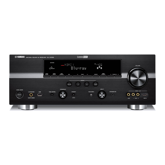
Page 3: Front Panels
Hävitä käytetty peristo valmistajan ohjeiden • Do not disassemble the batteries. mukaisesti. • Never heat batteries or throw them into fire. ■ FRONT PANELS Top view U model C, R, T, K, A, B, G, E, F, L models Front view RX-V2065 (U model) - Page 4 RX-V2065/HTR-6295 RX-V2065 (C, R, K, A, B, G, E, F, L models) RX-V2065 (T model) HTR-6295 (C model)
-
Page 5: Rear Panels
RX-V2065/HTR-6295 ■ REAR PANELS RX-V2065 (U model) RX-V2065 (C model) RX-V2065 (R model) - Page 6 RX-V2065/HTR-6295 RX-V2065 (T model) RX-V2065 (K model) RX-V2065 (A model)
- Page 7 RX-V2065/HTR-6295 RX-V2065 (B, G, E, F models) RX-V2065 (L model) HTR-6295 (C model)
-
Page 8: Remote Control Panels
RX-V2065/HTR-6295 ■ REMOTE CONTROL PANELS RAV296 RAV297 RAV298 (U model) (C, R, A, L models) (T, K, B, G, E, F models) RAV38 (U, C, R, T, K, A, B, G, E, F, L models) -
Page 9: Specifications
RX-V2065/HTR-6295 ■ SPECIFICATIONS ■ Audio Section Signal to Noise Ratio (IHF-A network) Minimum RMS Output Power (Power Amp. Section) PHONO (MM) to REC OUT (Input shorted 5 mV) (20 Hz to 20 kHz, 0.08 % THD, 8 ohms) U, C, R, T models ............ 86 dB or more FRONT L/R .............130 W + 130 W... - Page 10 [HTR-6295] Black color ................C model Bluetooth is a registered trademark of Bluetooth SIG and is used by Accessories Yamaha in accordance with a license agreement. Remote control ................x 1 Simplified remote control ..............x 1 Battery (R03, AAA, UM-4) .............x 2 Lithium battery (CR2025) ..............x 1...
- Page 11 RX-V2065/HTR-6295 • DIMENSIONS “SILENT CINEMA” is a trademark of Yamaha Corporation. Top view SIRIUS, XM and all related marks and logos are trademarks of Sirius XM Radio Inc. and its subsidiaries. All rights reserved. Service not available in Alaska and Hawaii.
- Page 12 RX-V2065/HTR-6295 • SOUND FIELD PARAMETERS Category Program MOVIE ● Standard ● ● ● ● ● ● ● ● ● ● ● Spectacle ● ● ● ● ● ● ● ● ● ● ● Sci-Fi ● ● ● ● ● ●...
- Page 13 RX-V2065/HTR-6295 • SET MENU TABLE MAIN MENU SUB-MENU PARAMETER VALUE [INITIAL VALUE] 1 • Speaker Setup 1 Auto Setup (YPAO) Extra Speaker Assignment [Zone2] / Zone2 + Zone3 / Presence / None EQ Type [Natural] / Flat / Front Start...
- Page 14 RX-V2065/HTR-6295 MAIN MENU SUB-MENU PARAMETER VALUE [INITIAL VALUE] 3 • Function Setup 1 HDMI HDMI Control On / [Off] On / [Off] Standby Through * This menu is available only when “HDMI Control” is set to “Off” . [Amplifier] / TV / Amplifier + TV Audio Output * This menu is available only when “HDMI Control”...
- Page 15 RX-V2065/HTR-6295 MAIN MENU SUB-MENU PARAMETER VALUE [INITIAL VALUE] SURROUND DECODE Surround Decoder Pro Logic / PL IIx Movie / PL IIx Music / Decode Type Pro Logic PL IIx Game / Neo:6 Cinema / Neo:6 Music / Neural Sur. (U model)
-
Page 16: Internal View
RX-V2065/HTR-6295 ■ INTERNAL VIEW OPERATION (2) P.C.B. OPERATION (9) P.C.B. (R, T, K, A, B, G, E, F, L models) HD RADIO TUNER (U model) VIDEO (4) P.C.B. OPERATION (8) P.C.B. ACDC (1) P.C.B. MAIN (1) P.C.B. DIGITAL (3) P.C.B. -
Page 17: Disassembly Procedures
RX-V2065/HTR-6295 ■ DISASSEMBLY PROCEDURES (Remove parts in the order as numbered.) Disconnect the power cable from the AC outlet. 1. Removal of Top Cover 2. Removal of Front Panel and Sub-Chassis Unit a. Remove 4 screws ( ① ), 5 screws ( ② ) and screw ( ③ ). - Page 18 RX-V2065/HTR-6295 3. Removal of GUI, DIGITAL (1) and (3) P.C.B.s 4. Removal of AMP Unit a. Remove 2 screws ( ⑦ ). (Fig. 2) a. Remove 3 screws ( ⑬ ) and 4 screws ( ⑭ ). (Fig. 2) b. Remove 3 screws ( ⑮ ). (Fig. 2) b.
- Page 19 RX-V2065/HTR-6295 When checking the P.C.B.s: • Place the P.C.B.s (with rear panel) upright. (Fig. 3) • Connect the ground points of the heatsink, rear panel and MAIN (1) P.C.B. (G1000) to the chassis with a ground lead or the like. (Fig. 3) •...
-
Page 20: Updating Firmware
RX-V2065/HTR-6295 ■ UPDATING FIRMWARE Note) The user memories (sound field parameters, system memory, tuner presetting, etc.) are preserved even after the firmware is written. When replacing the following parts, be sure to write the latest firmware. Replaced parts Writing method using the USB Writing method using PC (RS232C) DIGITAL P.C.B. - Page 21 RX-V2065/HTR-6295 Supplementary information: In this unit, it is possible to check the firmware version by using the ADVANCED SETUP menu as well as the self- diagnostic function menu. Follow the procedures below. 1. While pressing the “STRAIGHT” key of this unit, press the “MAIN ZONE ON/OFF” key of this unit to turn on the power.
-
Page 22: Required Tools
• USB storage device • Firmware RX-V2065 : RX-V2065_xxxx.bin HTR-6295 : HTR-6295_xxxx.bin ● Preparation 1. Download the latest firmware from the specified download source to the folder of the PC. 2. Copy the latest firmware from the PC to the root folder of the USB storage device. - Page 23 RX-V2065/HTR-6295 3. When writing of the firmware is completed, “UPDATE SUCCESS” is displayed. When “UPDATE FAIL” is displayed before writing is completed, perform the operation procedures from step 1 to 2 again. 4. Press the “MAIN ZONE ON/OFF” key of this unit to turn off the power.
- Page 24 RX-V2065/HTR-6295 Writing method using PC (RS232C) ● Required Tools ● Preparation and precautions • Download the firmware downloader program • Firmware downloader program and the firmware from the specified source to the For main microprocessor: same folder of the PC.
- Page 25 RX-V2065/HTR-6295 ● Operation Procedures Writing to the main microprocessor With the power cable of this unit disconnected from the AC outlet, start up DSP_FLASHER_v3.0.exe. The screen appears as shown below. (Fig. 2) Click [...] and select the firmware name. (Fig. 2) V265xxxx.mot...
- Page 26 RX-V2065/HTR-6295 Connect the power cable of this unit to the AC outlet. Click [E.P.] to start writing. (Fig. 3) When writing of the firmware is completed, “Program Finished!” is displayed. (Fig. 3) Click [OK]. (Fig. 3) Click [EXIT] to end DSP_FLASHER_v3.0.exe. (Fig. 3) Writing being executed.
- Page 27 RX-V2065/HTR-6295 Writing to DSP With the power cable of this unit disconnected from the AC outlet, start up DSP_FLASHER Ver2.7.exe. The screen appears as shown below. (Fig. 4) Click [Vx61 DSP]. (Fig. 4) Fig. 4 Click [...] and select the firmware name. (Fig. 5)
- Page 28 RX-V2065/HTR-6295 Click [RDY]. (Fig. 6) Fig. 6 While pressing the “PURE DIRECT” key of this unit, connect the power cable of this unit to the AC outlet. (Fig. 7) Writing is started automatically. (Fig. 7) This unit “PURE DIRECT” key Writing being executed.
- Page 29 RX-V2065/HTR-6295 When writing of the firmware is completed, “Vx61 DSP Flash finished!” is displayed. (Fig. 3) Click [EXIT] to end DSP_FLASHER_v2.7.exe. (Fig. 8) Fig. 8 Start up the self-diagnostic function and select “25.ROM VER/SUM/PORT” menu. Using the sub-menu, have the firmware version and checksum displayed, and then check that they are the same as written ones.
-
Page 30: Self-Diagnostic Function
RX-V2065/HTR-6295 ■ SELF-DIAGNOSTIC FUNCTION CAUTION! Do not disconnect the power cable of this unit from the AC outlet while this unit is in the self-diagnostic function mode, otherwise the user memories (input rename, sound field parameters, system memory, tuner presetting, etc.) will be initialized. - Page 31 RX-V2065/HTR-6295 Main menu Sub-menu VIDEO CHECK DIGITAL COMPONENT DIGITAL CVBS DIGITAL Y/C (B, G, E, F models) ANALOG BYPASS TEST PATTERN VIDEO INFORMATION XM STATUS (U model) 1k -1dB /44kHz 1k -61dB /44kHz Mute /44kHz XM Tone /44kHz ISO Tone /44kHz...
- Page 32 RX-V2065/HTR-6295 Main menu Sub-menu IF STATUS (Not applied to these models.) DSP STATUS BUS CHECK TI BUS BF LOOP NO MENU Invalidity PROTECTION HISTORY HISTORY 1 HISTORY 2 HISTORY 3 HISTORY 4 NO MENU Invalidity UPDATE TI FLASH BOOT (Not applied to these models.)
- Page 33 RX-V2065/HTR-6295 ● Starting Self-Diagnostic Function While pressing those 2 keys of this unit as shown in the figure below, press the “MAIN ZONE ON/OFF” key to turn on the power. The self-diagnostic function mode is activated. Keys of this unit U, C, R, K, A, B, G, E, F, L models While pressing these keys, turn on the power.
- Page 34 RX-V2065/HTR-6295 ● Display provided when Self-Diagnostic Function started The display is as described below depending on the situation when the last time the power to this unit is turned off. 1. When the power is turned off by usual operation: The FL display of this unit displays “NO PROTECT”...
- Page 35 RX-V2065/HTR-6295 2-2. When the protection function worked due to a short between speaker terminals. I P R O T E C T : x x x AD value when the protection function is working Cause: The line between speaker terminals is shorted.
- Page 36 RX-V2065/HTR-6295 2-4. When the protection function worked due to abnormal voltage in the power supply section. P R V P R T : x x x AD value when the protection function is working Cause: The voltage in the power supply section is abnormal.
- Page 37 RX-V2065/HTR-6295 ● Operation procedure of Main menu and Sub-menu There are 27 main menu items, each of them having sub-menu items. Main menu selection Select the main menu using “PROGRAM” knob. Sub-menu selection Select the sub-menu using “SCENE RADIO” (forward) and “SCENE CD” (reverse) keys.
- Page 38 RX-V2065/HTR-6295 ● Details of Self-Diagnostic Function menu 1. BYPASS Using the sub-menu, it is possible to select ANALOG BYPASS output or DSP BYPASS output. ANALOG BYPASS The analog input audio signal is output to FRONT L/R in PURE DIRECT. 1 . A N A L O G B Y P A S...
- Page 39 RX-V2065/HTR-6295 DSP BYPASS FL / FR LC89058 (DECODE) C / SW (POST PROCESSING) TI D70Y SL / SR SBL / SBR PCM1803 DRAM (Shaded items not used in this example) 2. RAM THROUGH Using the sub-menu, it is possible to select MARGIN output or FULL BIT output.
- Page 40 RX-V2065/HTR-6295 RAM FULL BIT The audio signal is output in digital full bit without including the head margin. The SUBWOOFER signal is output but not in digital full bit. 2 . R A M F U L L A L L...
- Page 41 RX-V2065/HTR-6295 RAM FULL CENTER The audio signal is output to only CENTER in digital full bit without including the head margin. 2 . R A M F U L L C INPUT: AV5 ANALOG SPEAKER OUT: 1 kHz, SUBWOOFER OUTPUT: 50 Hz...
- Page 42 RX-V2065/HTR-6295 3. HDMI AUDIO Using the sub-menu, the audio signals input to HDMI IN are selected and output. When selecting “DSD”, be sure to connect an HDMI unit equipped with DSD output function to this unit. SPDIF 3 . S P D I F SPDIF signal is output.
- Page 43 RX-V2065/HTR-6295 FRONT : SML 0dB 4 . F R N T : S M L 0 d B The FRONT L/R signal, when 90 Hz or lower, is mixed to the channel specified by LFE/BASS. CENTER : NONE 4 . C E N T E R : N O N E The CENTER signal is assigned to FRONT L/R.
- Page 44 RX-V2065/HTR-6295 5. MULTI CH-INPUT The input source “MULTI CHANNEL INPUT” is selected. Using the sub-menu, it is possible to select the 6 ohms/8 ohms. When LIM / PLDET / THM menu is selected, keys become non-operable. However, it is possible to advance to the next main menu by turning the “PROGRAM” knob of this unit.
- Page 45 RX-V2065/HTR-6295 LIM / PLDET / THM LIM: Setting value of LIM (Limiter control) Do not change the value settings because this menu is only for the use of development staff. PLDET: Power limiter detection The A/D conversion value during operation is displayed.
- Page 46 RX-V2065/HTR-6295 FL/GUI CHECK This menu is used to check the FL display and video control sections. When checking the video control section, connect a TV monitor to this unit with a component video cable and video pin cable. Using the sub-menu, the FL display section or video control section switches as shown below.
- Page 47 RX-V2065/HTR-6295 8. MANUAL TEST The built-in noise generator of DSP outputs the test noise through the channels specified by using the sub-menu. The noise frequency for LFE is 30 to 80 Hz. Other than that, the noise frequency is 500 Hz to 2 kHz.
- Page 48 RX-V2065/HTR-6295 DC/TH Power amplifier DC (DC voltage) output is detected. Normal value: 32 to 74 (Reference voltage: 3.3 V=255) Temperature on the heatsink is detected. Normal value: 0 to 124 (Reference voltage: 3.3 V=255) If DC or TH becomes out of the normal value range, the protection function works to turn off the power.
- Page 49 RX-V2065/HTR-6295 DST/DK DST: Destination detection (Reference voltage: 3.3 V=255) DOCK type detection (Reference voltage: 3.3 V=255) D S T : 2 1 1 D K : 2 5 5 Destination detection for AD port Pull-up resistance 10 k-ohms Ohm (R3809 VIDEO P .C.B.) 1.2 k...
- Page 50 RX-V2065/HTR-6295 10. VIDEO CHECK I2C check The I2C (Inter integrated circuit) bus line connection is checked. 0 : No error detected I 2 C : 0 0 0 0 0 0 0 0 1-3 : An error is detected 0 bit : SCALER (IC71, DIGITAL P.C.B.) 1 bit : VIDEO ENCODER (IC72, DIGITAL P.C.B.)
- Page 51 RX-V2065/HTR-6295 Digital CVBS (Video) The video signal is converted and output as shown below. D I G I T A L C V B S Digital CVBS (Video) DIGITAL DIGITAL IC71 IC7/15 ABT1012 DIGITAL DIGITAL Sil9134 I/P SCALER IC1/2 IC70...
- Page 52 RX-V2065/HTR-6295 Analog bypass The video signal is converted and output as shown below. A N A L O G B Y P A S S Analog bypass DIGITAL DIGITAL IC71 IC7/15 ABT1012 DIGITAL DIGITAL Sil9134 I/P SCALER IC1/2 IC70 Sil919185A...
- Page 53 RX-V2065/HTR-6295 11. XM STATUS (U model) This menu is used to check the output of XM Radio Antenna. 1 kHz, -1 dB / 44.1 kHz 1 k - 1 d B / 4 4 The test tone (1 kHz, -1 dB / 44.1 kHz) is output.
- Page 54 RX-V2065/HTR-6295 12. SIRIUS (U model) The SIRIUS information are displayed. SIRIUS: S I R I U S : - - Connection of the SIRIUS antenna module is checked. OK : Normal NG : Abnormal - - : No connected S R : F F 0 0 F F The connection information of the SIRIUS antenna module is displayed.
- Page 55 RX-V2065/HTR-6295 14. DOCK This menu is used to check the DOCK connector without the iPod itself. With the power to this unit turned off, short between pins No. 14 (TX) and No. 18 (RX), between pins No. 1 (PWR) and No.
- Page 56 The product ID of this unit written in HDMI module is displayed. 3143 : RX-V2065 3144 : HTR-6295 HDMI vendor name V N : Y A M A H A The vendor name “YAMAHA” of this unit written in HDMI module is displayed.
- Page 57 RX-V2065/HTR-6295 16. HDMI SELECT Using the sub-menu, the selected input signal is output to HDMI OUT. Support audio is set to “OTHER”. HDMI none H D M I N O N E No signal is output. HDMI in 1 H D M I I N 1 The signal input from HDMI “IN 1”...
- Page 58 RX-V2065/HTR-6295 HDMI up-conversion through DIGITAL DIGITAL IC71 IC7/15 ABT1012 DIGITAL DIGITAL Sil9134 I/P SCALER IC1/2 IC70 Up-conversion Sil919185A ADV7800 through VIDEO DIGITAL DECODER IC72 ADV7172 IC506 VIDEO ENCODER AK8814 17. USB The music file stored in the USB storage device is reproduced.
- Page 59 RX-V2065/HTR-6295 18. IF STATUS (Input function status) Not applied to these models. DSP status D S T : 7 1 0 E 0 F 2 3 9 0 19. BUS CHECK Communication and bus line connection between devices on the DIGITAL P.C.B. are checked.
- Page 60 RX-V2065/HTR-6295 21. PROTECTION HISTORY The history of protection function is displayed. Select this menu and press the “STRAIGHT” key, all history will be erased. Example History 1 2 1 - 1 . D c x x x L H : When the upper limit of the protection function is exceeded.
- Page 61 RX-V2065/HTR-6295 23. UPDATE Not applied to these models. UPDATE TI 2 3 . U P D A T E T I 24. FACTORY PRESET This menu is used to reserve/inhibit initialization of the back-up IC. PRESET INHIBIT (Initialization inhibited) / PRESET INHIBIT 2 4 .
- Page 62 RX-V2065/HTR-6295 25. ROM VER/SUM/PORT The firmware version, checksum values, model name and destination are displayed. The checksum is obtained by adding the data at every 8-bit for each program area and expressing the result as a 4-figure hexadecimal data. The figures in the diagram are given as reference only.
- Page 63 The model name and destination are displayed. V 2 0 0 0 U 0 2 7 MODEL detection value Detection value 15 – 46 Model name V2 (RX-V2065) H9 (HTR-6295) DESTINATION detection value Detection value 15 – 45 46 – 68 69 – 92 92 –...
- Page 64 RX-V2065/HTR-6295 26. SERIAL RS-232C loop back check This menu is used to check transmission and reception of the data, and the flow port of hardware. With the power to this unit turned off, short between pins No. 2 (RxD) and No. 3 (TxD), and between pins No. 7 (RTS) and No.
- Page 65 When IC513 of GUI P.C.B. or GUI P.C.B. is replaced, use this menu to restore the previous MAC address number. Yamaha Corporation will provide the setting procedure for proper operation. Please report the serial number of this unit to the following e-mail address for further instruction.
- Page 66 RX-V2065/HTR-6295 LINK CHECK A network cable connection is checked. 2 7 . N E T L N K : O K OK: Normal NG: Unconnected NETWORK loop back check This menu is used to check the NETWORK connector. With the power to this unit turned off, short between pins No. 1 (Tx+) and No. 3 (Rx+) and between pins No. 2 (Tx-) and No.
-
Page 67: Confirmation Of Idling Current Of Amp Unit
RX-V2065/HTR-6295 ■ CONFIRMATION OF IDLING CURRENT OF AMP UNIT ● Right after power is turned on, confirm that the voltage across the terminals of R1152 (SURROUND BACK Rch), R1154 (SURROUND Rch), R1150 (FRONT Rch), R1148 (CENTER), R1149 (FRONT Lch), R1153 (SURROUND Lch), R1151 (SURROUND BACK Lch) are between 0.1mV and 10.0mV. -
Page 68: Display Data
RX-V2065/HTR-6295 ■ DISPLAY DATA ● V4001 : 18-MT-09GNK (OPERATION P.C.B.) PATTERN AREA ● PIN CONNECTION Pin No. 68 67 Connection F2 NX 29 28 Pin No. Connection Note : 1) F1, F2 ..Filament pin 2) NP ..No pin 3) NX .. - Page 69 RX-V2065/HTR-6295 ● ANODE CONNECTION 1G-14G –...
-
Page 70: Ic Data
RX-V2065/HTR-6295 ■ IC DATA IC44: D70YE101BRFP266 (DIGITAL P.C.B.) Decoder/Post processor * No replacement part available. SPI0_SIMO EM_CKE SPI0_SOMI/I2C0_SDA EM_CLK AXR0[0] EM_WE_DQM[1] AXR0[1] EM_D[8] AXR0[2] AXR0[3] EM_D[9] EM_D[10] AXR0[4] AXR0[5]/SPI1_SCS EM_D[11] AXR0[6]/SPI1_ENA AXR0[7]/SPI1_CLK EM_D[12] EM_D[13] EM_D[14] AXR0[8]/AXR1[5]/SPI1_SOMI EM_D[15] AXR0[9]/AXR1[4]/SPI1_SIMO EM_D[0] AXR0[10]/AXR1[3]... - Page 71 RX-V2065/HTR-6295 Function Name TYPE PULL GPIO Detail of Function (P.C.B.) AHCLKX0/AHCLKX2 – McASP0 and McASP2 transmit master clock AMUTE0 – McASP0 mute output AMUTE1 – McASP1 mute output AHCLKX1 – McASP1 transmit master clock ACLKX1 – McASP1 transmit bit clock...
- Page 72 RX-V2065/HTR-6295 Function Name TYPE PULL GPIO Detail of Function (P.C.B.) EM_D[10] – EMIF data bus [lower 16-Bits] EM_D[9] – EMIF data bus [lower 16-Bits] CVDD EM_D[8] – EMIF data bus [lower 16-bits] EM_WE_DQM[1] – Write enable or byte enable for EM_D [15:8]...
- Page 73 RX-V2065/HTR-6295 Function Name TYPE PULL GPIO Detail of Function (P.C.B.) 123 CVDD 124 VSS 125 DVDD McASP0 serial data 8 or McASP1 serial data 5 or SPI1 data pin slave 126 /SPI1_SOMI – out master in McASP0 serial data 9 or McASP1 serial data 4 or SPI1 data pin slave in 127 /SPI1_SIMO –...
- Page 74 RX-V2065/HTR-6295 IC402: M66003-0131FP (OPERATION P.C.B.) FL display driver Display code CGROM SEG00 (35-bit x 166) (8-bit x 60) Segment SEG25 Code output write SEG26 circuit CGROM dot data SEG34 Serial data (35-bit x 16) write receive Code/ circuit SDATA command...
- Page 75 RX-V2065/HTR-6295 Pin No. Port Name Function Name Detail of Function Vcc1 Positive power supply for internal logic. SEG34 SEG33 SEG32 SEG31 SEG30 Segment output Connect to segment (anode) pins of VFD. SEG29 SEG28 SEG27 SEG26 Vcc2 Positive power supply for DIG and SEG outputs.
- Page 76 RX-V2065/HTR-6295 IC41: LC89058WD-E (DIGITAL P.C.B.) Digital audio interface receiver MOUT AUDIO XMODE Fs calculator GPIO0 Microcontroller 40 CL GPIO1 GPIO2 Cbit, Pc GPIO3 RXOUT2 RXOUT1 Input RERR Demodulation Selector & SDIN Data Lock detect Selector RDATA Clock RMCK Clock Selector...
- Page 77 RX-V2065/HTR-6295 Pin No. Function Name Detail of Function RXOUT1 RX0-6 input S/PDIF through output pin 1 5V withstand voltage TIL input level compatible S/PDIF input pin (connected to GND when RX1 is (pd) set) I(pd) Co-axial compatible S/PDIF input pin (supported demodulation sampling frequency of up to 96 kHz)
- Page 78 RX-V2065/HTR-6295 IC153: R2A15220FP (MAIN P.C.B.) 8-channel electronic volume with 11 input selector and tone control 49 48 46 45 38 37 34 33 TRER MUTE AVEE AVCC BASSR2 A VEE BASSR1 ADCL 0/-6/-12/-18dB TREL ADCR SUB2 BASSL2 AGND MAIN INR1...
- Page 79 RX-V2065/HTR-6295 Pin No. Port name Function Name Detail of Function AGND Analog ground of internal circuit SBROUT VOSBL Output pin of FL/FR/C/SW/SL/SR/SBL/SBR channel SBR Pre-OUT VOPSBL Pre-output pin of FL/FR/SL/SR/SBL/SBR channel SBRC Connects capacitor for reducing click noise of L/R/C/SW/SL/SR/SBL/SBR channel volume...
- Page 80 RX-V2065/HTR-6295 Pin No. Port name Function Name Detail of Function INR2 AU1L Input pin of L/R channel (Input selector) INL2 AU1R Input pin of L/R channel (Input selector) INR3 AV-6L Input pin of L/R channel (Input selector) INL3 AV-6R Input pin of L/R channel (Input selector)
- Page 81 RX-V2065/HTR-6295 IC20: M3087BFKBGP (DIGITAL P.C.B.) Main microprocessor Port P0 Port P1 Port P2 Port P3 Port P4 Port P5 Port P6 < > < > CC1 (3) Peripheral Functions Clock Generation Circuit A/D Converter: 1 circuit Timer (16 bits) Standard: 10 inputs...
- Page 82 RX-V2065/HTR-6295 Function Port Name Name Detail of Function (P.C.B.) TXD4 SCPU_MOSI Synchronous data output for SubCPU CLK4 SCPU_SCK Synchronous clock output for SubCPU P95/ANEX0/CLK4 P94/DA1/TB4in/ SCPU_CTS Input for transmission control for SubCPU (clear to send) CTS4/RTS4/SS4 P93/DA0/TB3in/ AMP_LMT Limiter control output...
- Page 83 RX-V2065/HTR-6295 Function Port Name Name Detail of Function (P.C.B.) /RESET /RESET MCU MCU MCU MCU [MCU] Reset /RESET Xout Xout MCU MCU MCU MCU [MCU] 20 MHz ceramic resonator Xout MCU MCU MCU MCU [MCU] MCU MCU MCU MCU [MCU]...
- Page 84 RX-V2065/HTR-6295 Function Port Name Name Detail of Function (P.C.B.) TxD1 RS232C data output P67/TXD1/SDA1/ 232C_MOSI Pull up at 100 k-ohms SRXD1 TxD1 E8a, ICP (In-Circuit Programmer) data output Vcc1 Vcc1 MCU MCU MCU MCU [MCU] Microprocessor power supply Vcc1 RxD1...
- Page 85 RX-V2065/HTR-6295 Function Port Name Name Detail of Function (P.C.B.) P133 HTX_VSEL P133/OUTC23 MCU MCU MCU MCU [MCU] Microprocessor GND Video I/P & Scaler IC reset P132 ABT_N_RST VID_PON=L: Low fix P132/OUTC26 L: reset Vcc2 Vcc2 MCU MCU MCU MCU [MCU]...
- Page 86 RX-V2065/HTR-6295 Function Port Name Name Detail of Function (P.C.B.) Speaker impedance relay control GND pull down SP_IMP [HiZ] Set to 8 ohms: Hi-Z (Relay OFF, B voltage High) Set to 6 ohms plus during rising temperature: High (Relay ON, B...
- Page 87 RX-V2065/HTR-6295 Function Port Name Name Detail of Function (P.C.B.) XM Radio power supply ON/OFF control XM_PON (U model) P14/D12 H: ON, L: OFF (C, R, T, K, A, B, G, E, F, L, J models) DOCK power supply ON/OFF control...
- Page 88 RX-V2065/HTR-6295 Function Port Name Name Detail of Function (P.C.B.) ISRXD0 P152/AN152/ E2R_MISO Synchronous data input for EEPROM ISRXD0/RXD5 FL driver, OSD, IO extended IC (Video), EEPROM synchronous clock ISCLK0 P151/AN151/ FLD_SCK output ISCLK0/CLK5 Inhalation attention of power supply off device...
- Page 89 RX-V2065/HTR-6295 Key detection for A/D port Key input (A/D) pull-up resistance 10 k-ohms +1.0k +1.0k +1.5k +1.5k +2.2k +3.3k +4.7k +22.0k +33.0k 0 – 0.15 0.15 – 0.42 0.43 – 0.70 0.71 – 0.97 0.98 – 1.24 1.25 – 1.53 1.54 –...
- Page 90 RX-V2065/HTR-6295 IC505: AD91089ZSKBC (GUI P.C.B.) Sub-microprocessor * No replacement part available. Event controller/ JTAG test Watch dock timer Core timer and emulation Real time clock Voltage regulator UART port IrDA® Memory L1 instruction L1 data management memory memory unit Timer0, Timer1, Timer2...
- Page 91 RX-V2065/HTR-6295 Memory Interface Synchronous memory control Function Name Detail of Function Function Name Detail of Function 121 ADDR19 167 SRAS O Row address strobe 122 ADDR18 166 SCAS O Column address strobe 165 SWE O Write enable 123 ADDR17 173 SCKE...
- Page 92 RX-V2065/HTR-6295 JTAG port Clock Function Name Detail of Function Function Name Detail of Function 94 TCK JTAG clock Clock/Crystal input (This pin needs to 10 CLKIN be at a level or clocking.) 87 TDO O JTAG serial data out 11 XTAL...
- Page 93 RX-V2065/HTR-6295 Supplies Function Name Detail of Function Function Name Detail of Function VDDEXT I/O power supply VDDINT Core power supply G External ground 18 VDDRTC Real-time clock power supply...
-
Page 94: Pin Connection Diagrams
RX-V2065/HTR-6295 ■ PIN CONNECTION DIAGRAMS • ICs 74LVC08APW 74LVC1G08GW 74LVC245APW,118 CS230003-CZZR CXB1442AR-T4 74LVC32APW ABT1012Q100 ADV7800BSTZ-80 ADV7172KST BA00JC5WT-V5 LAN9217-MT AD91089ZSKBC AK8814VQ SiI9134CTU BD9323EFJ-E2 D70YE101BRFP266 FHP3350IM14X K4S641632N-LC60000 M3087BFKBGP SiI9233ACTU F2621E-01-TR ISL83385EIBZ-T ISP1760BE KIA7912PI K4S560832J-UC75000 K8P6415UQB-PI4B000 LA73050-TLM-E LC709004A-TLM-E LC72725KM-UY-TLM-E... - Page 95 RX-V2065/HTR-6295 LC89058WD-E LE25LB2562M-TLM-E LM19CIZ/LF M66003-0131FP-R NE5532DR NJM2068MD-TE2 LE25LB643M-TLM-E NJM4565M (TE1) NJM2388F05 NJM2396F05 NJM2581M NJM2867F3-05 NJM7812FA NJM78M05DL1A (TE1) 1. IN 1. V 2. V 1: INPUT 2. V 3: IN 3. GND 2: GND 3. GND 1: OUT 2: COM 4. ON/OFF CONTROL 3: OUTPUT 4.
- Page 96 RX-V2065/HTR-6295 • Diodes 1N4002S 1SS355 D15XBN20-7001 15A HT18G 1SS133 1SS176 Anode Anode Anode – Cathode Cathode Cathode + AC MAZ8033GHL 3.4V MTZJ10B MTZJ5.1B RB051L-40 P6KE100A UDZ5.1B MTZJ12B MTZJ5.1C MAZ8036GLL 3.5V MTZJ13B MTZJ6.8C MTZJ2.4B MTZJ22C Anode Anode Anode Anode MTZJ3.3B MTZJ39D...
- Page 97 RX-V2065/HTR-6295 • Transistors 2N5401C-AT/P 2SA1145 2SA1576A 2SA1708 2SA2168 2SC6011/2SA2151 2SA1015-Y 2SC2705 2SC5291 2N5551C-AT 2SC1815 Y 2SC1740S 2SC4081 T106 2SD1938F 2SD1915F DTA114EKA 2SC3906K DTA143EKA DTA144EKA DTC114EKA DTC144EKA 1: GND 2: IN 3: OUT KRA102M-AT/P KTA1046-Y-U/P KTA1517S MCH6336-TL-E μPA672T-T1-A KTA1837-U/P KRC105M-AT KTC3875S KTC3911S 1.
-
Page 98: Block Diagrams
RX-V2065/HTR-6295 ■ BLOCK DIAGRAMS ANALOG AUDIO Section Block Diagram → → VIDEO HP Relay Control MAIN SCHEMATIC DIAGRAM to DIGITAL AUDIO Section SCHEMATIC DIAGRAM AMP_OLV AV-1 Power Limit Detect OPTICAL PHONES IC152 AV-2 RY341 DC_PRT COAXIAL DC Protection RY342 AV-3... - Page 99 RX-V2065/HTR-6295 DIGITAL AUDIO Section Block Diagram OUT1 OUT2 HDMI IN (Front) IC95 HDMI Switch HDMI Switch Equalizer DCLK DCLK SCK/DCLK SII9185ACTU SII9185ACTU CXB1442AR WS/DR0 SD0/DL0 SD1/DR1 SD2/DL1 HDMI Rx SD3/DR2 SPDIF/DL2 SII9233ACTU MCLK IC11 IC15 Selector HDMI Tx HDMI Tx...
- Page 100 RX-V2065/HTR-6295 VIDEO Section Block Diagram → HDMI DIGITAL SCHEMATIC DIAGRAM HDMI Tx OUT2 SiI9134 1-3,88 OUT1 XL502 IC15 16.666MHz → HDMI Tx SCHEMATIC DIAGRAM SiI9134 IC505 (B, G, E, F models) 28.636363MHz PPI[0:7] D[0:7] IC95 IN (Front) IC506 IC76-78 PPI_FS[1:3]...
- Page 101 RX-V2065/HTR-6295 Power Supply Section Block Diagram SP_IMP RY100 Power AMP RY100 TRIGGER OUT → VIDEO Q3203 SCHEMATIC DIAGRAM Tuner IC103 IC63 Analog Audio +12V +12A Volume → MAIN Analog Audio -12V -12A SCHEMATIC DIAGRAM Volume IC104 FL filament Q3306 -37V...
-
Page 102: Printed Circuit Boards
POINT A XL20 (Pin 20 of IC20) POINT B 1 / CB24 (+3.3M), 2 / CB24 (/RESET) POINT C XL41 (Pin 28 of IC40) POINT D XL42 (Pin 29 of IC41) RX-V2065/HTR-6295 ■ PRINTED CIRCUIT BOARDS CB24 CB24 (+3.3M) (+3.3M) DIGITAL (1) P.C.B. - Page 103 RX-V2065/HTR-6295 DIGITAL (1) P.C.B. (Side B) U model C, R, T, K, A, B, G, E, F, L models B, G, E, F models • Semiconductor Location Ref no. Location D153 D201 D202 D203 D204 D404 D600 U model D602...
- Page 104 RX-V2065/HTR-6295 DIGITAL (2) P.C.B. DIGITAL (3) P.C.B. (Side A) (Side A) U model PHONO C, R, T, K, A, B, G, E, F, L models RS-232C TRIGGER OUT +12V 0.1A MAX. PJ80 CB84 JK82 JK81 IC97 +5VPower GND/+Vcc IC80 Reserves...
- Page 105 RX-V2065/HTR-6295 DIGITAL (2) P.C.B. DIGITAL (3) P.C.B. (Side B) (Side B) U model • Semiconductor Location Ref no. Location D962 D963 D964...
- Page 106 RX-V2065/HTR-6295 OPERATION (1) P.C.B. (Side A) DIGITAL (1) HDMI (CB20) THROUGH indicator HD_LED +3.3DSP +5DSP DGND +3.3M DGND DGND MASW MIC_N_DET PSW_DET REM_IN PD_LED FLD_N_RS FLD_N_CS OPERATION (6) FLD_MOSI FLD_SCK (CB474) RMS_OUT KEY1 KEY2 PRG_RA PRG_RB ISEL_RA ISEL_RB VOL_RA ZONE3...
- Page 107 RX-V2065/HTR-6295 OPERATION (1) P.C.B. (Side B) 49 48 IC401 • Semiconductor Location Ref no. Location D4001 D4002 D4003 D4004 D4005 D4006 D4007 IC401 IC402 Q4001 Q4002 Q4003 Q4004 Q4006 Q4007 Q4008 Q4009 Q4010 Q4011 Q4012...
- Page 108 RX-V2065/HTR-6295 OPERATION (2) P.C.B. (Side A) MAIN (1) MAIN (1) (CB155) MAIN (1) MAIN (1) (CB152) (CB153) (CB154) CB457 CB451 CB454 CB456 CB459 CB460 +12V -12V VIDEO (1) VIDEO (1) (CB332) (CB303) DIGITAL AUDIO OPTICAL CB452 CB455 CB458 SIRIUS CB461...
- Page 109 RX-V2065/HTR-6295 OPERATION (2) P.C.B. (Side B) IC451 IC452 IC453 IC454 U model • Semiconductor Location Ref no. Location IC451 IC452 IC453 IC454...
- Page 110 RX-V2065/HTR-6295 OPERATION (3) P.C.B. OPERATION (4) P.C.B. OPERATION (5) P.C.B. OPERATION (6) P.C.B. (Side A) (Side A) (Side A) (Side A) VIDEO AUX VIDEO AUDIO (CB550) HP_N_DET MAIM ZONE SW471 ON/OFF VIDEO (1) W4407 (W3401) JK472 CB473 VIDEO (6) CB471...
- Page 111 RX-V2065/HTR-6295 OPERATION (3) P.C.B. OPERATION (4) P.C.B. OPERATION (5) P.C.B. OPERATION (6) P.C.B. (Side B) (Side B) (Side B) (Side B) OPERATION (8) P.C.B. OPERATION (9) P.C.B. OPERATION (10) P.C.B. (Side B) (Side B) (Side B) C, R, T, K, A, B, G, E, F, L models •...
- Page 112 RX-V2065/HTR-6295 MAIN (1) P.C.B. (Side A) AUDIO1 AUDIO2 MULTI CH INPUT AUDIO ZONE2 ZONE3 PRE OUT OPTICAL COAXIAL COAXIAL OPTICAL FRONT SURROUND SUR. SUBWOOFER FRONT SURROUND SUR. SUBWOOFER (TV) (CD) BACK BACK CENTER SINGLE CENTER OPERATION (2) (CB451) PJ152 PJ153...
- Page 113 RX-V2065/HTR-6295 MAIN (1) P.C.B. (Side B) IC152 IC154 51 50 • Semiconductor Location Ref no. Location Ref no. Location D1001 Q1008 D1002 Q1009 D1003 Q1010 100 1 D1004 Q1011 D1005 Q1012 D1006 Q1013 D1007 Q1014 D1008 Q1057 D1009 Q1058 D1010...
- Page 114 RX-V2065/HTR-6295 MAIN (2) P.C.B. MAIN (3) P.C.B. MAIN (4) P.C.B. (Side A) (Side A) (Side A) R, L models R, L models CB112 CB111 R model POWER TRANSFORMER W122A L model MAIN (1) W121A W125A MAIN (1) (CB101) (W101A)(W102A)(W103A)(W104A)(W105A) VOLTAGE...
- Page 115 RX-V2065/HTR-6295 MAIN (2) P.C.B. MAIN (3) P.C.B. MAIN (4) P.C.B. (Side B) (Side B) (Side B) R, L models R, L models MAIN (6) P.C.B. (Side B)
- Page 116 RX-V2065/HTR-6295 SPEAKERS VIDEO (1) P.C.B. (Side A) FRONT CENTER SURROUND R SURROUND BACK/ BI-AMP COMPONENT VIDEO VIDEO MONITOR OUT COMPONENT VIDEO VIDEO VIDEO PJ303 PJ304 PJ301 PJ305 PJ306 W3301B CB343 CB342 CB347 CB348 W3401 CB346 CB344 OPERATION (2) CB340 (CB459)
- Page 117 RX-V2065/HTR-6295 VIDEO (1) P.C.B. (Side B) IC307 IC305 IC306 IC308 IC301 IC302 IC303 IC310 • Semiconductor Location Ref no. Location IC321 B, G, E, F models D3309 D3310 D3311 C, R, T, K, A, B, G, E, F, L models...
- Page 118 RX-V2065/HTR-6295 VIDEO (3) P.C.B. VIDEO (4) P.C.B. (Side A) (Side A) ACDC (1) (CB604) DIGITAL (1) (CB21) W3601 CB381 JK361 JK362 REMOTE W3801 CB382 VIDEO (9) P.C.B. (Side A) DIGITAL (1) (CB7) B, G, E, F models DIGITAL (1) (CB24) VIDEO (6) P.C.B.
- Page 119 RX-V2065/HTR-6295 VIDEO (3) P.C.B. VIDEO (4) P.C.B. (Side B) (Side B) VIDEO (9) P.C.B. (Side B) B, G, E, F models VIDEO (6) P.C.B. (Side B) IC391 • Semiconductor Location Ref no. Location D3601 D3602 D3801 D3802 D3803 D3804 D3805...
- Page 120 RX-V2065/HTR-6295 POINT G XL502 (Pin 10 of IC505) GUI P.C.B. GUI P.C.B. (Side A) (Side B) No replacement part available. NETWORK CB551 OPERATION (5) (W4407) POINT H XL500 (Pin 8 of IC521) USBR USBL DIGITAL (1) (CB64) POINT L XL501 (Pin 8 of IC522)
- Page 121 RX-V2065/HTR-6295 ACDC (1) P.C.B. ACDC (1) P.C.B. (Side A) (Side B) ACDC (2) (W6001B) MAIN (4) U, C, T, K, A, B, G, E, F models (W126A)(W126B) R, L models W6001A ACDC (2) CB603 (W6002B) U, C, T, K, A, B, G, E, F models...
- Page 122 RX-V2065/HTR-6295 ACDC (2) P.C.B. ACDC (2) P.C.B. (Side A) (Side B) U, C, T, K, A, B, G, E, F models U, C, T, K, A, B, G, E, F models W6001B POWER TRANSFORMER W6002B ACDC (1) (W6001A)(W6002A) ACDC (3) P.C.B.
-
Page 123: Schematic Diagrams
RX-V2065/HTR-6295 SCHEMATIC DIAGRAMS DIGITAL 1/7 HDMI IN (Front) CB95 DIGITAL (3) DIGITAL (2) JK81 17.8 12.0 17.8 17.1 17.8 12.0 TRIGGER OUT JK82 17.8 12.0 17.8 17.1 CB87 17.8 17.8 12.0 CB81 17.8 CB97 -5.5 -3.3 IC96 Page 124 to DIGITAL (1)_CB30 -5.5... - Page 124 RX-V2065/HTR-6295 POINT A XL20 (Pin 20 of IC20) DIGITAL 2/7 To thermal protector (C, R, T, K, A, B, G, E, F, L models) Page 136 Page 130 Page 136 Page 139 Page 133 Page 135 to VIDEO (3)_CB382 to OPERATION (1)_CB401...
- Page 125 RX-V2065/HTR-6295 DIGITAL 3/7 Page 137 to GUI_CB500 To DIGITAL 7/7 To DIGITAL 2/7 IC42 IC51 12.0 To DIGITAL 4/7 IC43 IC43 IC46 -11.6 IC45 IC51 IC41: LC89058WD-E Digital audio interface receiver XM DT IC MOUT AUDIO XMODE Fs calculator GPIO0...
- Page 126 RX-V2065/HTR-6295 DIGITAL 4/7 IC61: PCM1781DBQR Page 137 Audio digital-to-analog converter to GUI_CB503 Audio LRCK Serial Output Amp DATA Port Low-Pass Filter 4 x 8 Oversampling Enhanced Digital Multilevel (FMT) Filter Delta-Sigma With Modulator MS (DEMP0) Function Serial Control Control DIGITAL (1)
- Page 127 RX-V2065/HTR-6295 DIGITAL 5/7 Page 136 Page 134 to VIDEO (9)_CB391 to VIDEO (1)_CB304 (B, G, E, F models ) IC76-78: SN74LVTH245APW 3.3 V ABT octal bus transceivers with 3-state outputs IC73 IC74 IC72 To DIGITAL 2/7 IC75: TC7WZ32FK (TE85L, F)
- Page 128 RX-V2065/HTR-6295 DIGITAL 6/7 Page 123 to DIGITAL (2)_CB96 HDMI 4 HDMI 3 HDMI 2 HDMI 1 (BD/DVD) To DIGITAL 7/7 To DIGITAL 7/7 IC1, 2: SiI9185ACTU HDMI switch HDMI SWITCH HDMI SWITCH EDID Block No replacement part available. Config. R0X0+/-...
- Page 129 RX-V2065/HTR-6295 DIGITAL 7/7 HDMI OUT 1 HDMI OUT 2 To DIGITAL 6/7 (HDMI CONTROL) CB15 IC5: R1172S121D-E2-F IC12 Voltage regulator Vref Current Limit IC16 IC10 Pin No. Symbol Description VOUT Output Pin of Voltage Regulator 2, 5 Ground Pin Chip Enable Pin...
- Page 130 RX-V2065/HTR-6295 OPERATION 1/2 OPERATION (3) IC401: NJM4565M OPERATION (1) Dual operational amplifier 2, 6 –INPUT OUTPUT 1, 7 +INPUT 3, 5 CB477 JK472 Page 135 V– to VIDEO (1)_W3401 PHONES -31.0 -31.0 IC402: M66003-0131FP-R 18 digit 5 x 7 segment VFD controller/driver -33.1...
- Page 131 RX-V2065/HTR-6295 OPERATION 2/2 OPERATION (8) SURROUND BACK L 12.0 OPERATION (2) 12.0 12.0 12.0 -11.7 -11.7 12.0 SIRIUS ZONE2/PRESENCE 12.0 SPEAKERS -11.7 ZONE3 -11.7 Page 126 Page 126 Page 126 to DIGITAL (1)_CB62 to DIGITAL (1)_CB63 -11.6 -11.6 to DIGITAL (1)_CB61...
- Page 132 RX-V2065/HTR-6295 MAIN 1/2 MAIN (1) 63.8 63.8 63.8 63.7 55.5 54.9 CENTER 63.4 -1.0 -0.4 54.9 55.9 -1.0 -0.5 -0.5 2SC3906K 2SC3906K -0.5 -1.0 -0.5 -1.0 -63.7 -55.5 -63.7 -56.1 -56.1 W107 Page 135 -56.7 to VIDEO (1)_CB342 63.8 63.8 CB104 55.5...
- Page 133 RX-V2065/HTR-6295 MAIN 2/2 AUDIO ZONE2 ZONE3 AV 1 AV 2 AV 3 AV 4 AV 5 AV 6 AV OUT AUDIO 1 AUDIO 2 MULTI CH INPUT PRE OUT FRONT SURROUND SURROUND BACK SUBWOOFER CENTER FRONT SURROUND SURROUND BACK SUBWOOFER 1...
- Page 134 RX-V2065/HTR-6295 VIDEO 1/3 Page 124 CB302 to DIGITAL (1)_CB29 IC301 -4.8 AV 1 IC301 IC309 COMPONENT -4.8 VIDEO IN -4.8 IC301-303: TC74HC4053AF Analog multiplexer/demultiplexer CB301 INHIBIT -4.8 AV 2 INPUT STATES LEVEL BINARY TO 1-OF-8 "ON" CHANNEL (S) INHIBIT COMPONENT...
- Page 135 RX-V2065/HTR-6295 VIDEO 2/3 VIDEO (1) JK321 CB321 (B, G, E, F models) Page 131 Page 131 to OPERATION (8)_CB463 to OPERATION (8)_CB464 RDS DECODER W3402 to AM/FM TUNER (C, R, T, K, A, B, G, E, F, L models) IC321...
- Page 136 RX-V2065/HTR-6295 VIDEO 3/3 Page 124 to DIGITAL (1)_CB21 VIDEO (4) JK361 REMOTE W3601 JK362 Page 127 to DIGITAL (1)_CB73 DETECTOR S VIDEO JK391 IC391 AV 5 IC353 IC391 IC353 IC391 VIDEO (9) B, G, E, F models IC353 W3701B W3702B...
- Page 137 RX-V2065/HTR-6295 GUI 1/2 Page 126 to DIGITAL (1)_CB64 IC501, 502: SN74LV163APWR 4-bit synchronous binary counters CB500 LOAD Page 125 to DIGITAL (1)_CB45 IC521 IC521 CB501 1,2T/1C3 IC521 IC521 Page 124 IC506 1,2T/1C3 to DIGITAL (1)_CB28 IC509 1,2T/1C3 IC522 IC522 IC522...
- Page 138 RX-V2065/HTR-6295 GUI 2/2 IC551: ISP1760BE Embedded hi-speed USB host controller VCC(I/O) 37 to 39, 41 to 43, 10, 40, 48, 59, 67, 45 to 47, 49, 51, 75, 83, 94, 104, 115 ISP1760BE 52, 54, 56 to 58, XTAL1 60 to 62, 64 to 66,...
- Page 139 RX-V2065/HTR-6295 ACDC ACDC (2) U, C, T, K, A, B, G, E, F models AC IN W6001B W6002B Page 132 to MAIN (4)_W126A, W126B (R, L models) W6001A W6002A ACDC (1) IC601: TOP255MN TOPswitch-HX CONTROL (C) DRAIN (D) INTERNAL SUPPLY...
-
Page 140: Replacement Parts List
RX-V2065/HTR-6295 ■ REPLACEMENT PARTS LIST • ELECTRICAL COMPONENT PARTS WARNING ● Components having special characteristics are marked and must be replaced with parts having specifications equal to those originally installed. ABBREVIATIONS IN THIS LIST ARE AS FOLLOWS: C.A.EL.CHP : CHIP ALUMI.ELECTROLYTIC CAP L.EMIT... - Page 141 RX-V2065/HTR-6295 P.C.B. DIGITAL Ref No. Part No. Description Markets Ref No. Part No. Description Markets WS305800 P.C.B. DIGITAL US062470 C.CE.CHP 470pF 50V B WS305900 P.C.B. DIGITAL CRTKAL(V2065) WD758300 C.CE.CHP 10uF WS306700 P.C.B. DIGITAL C(6295) C89-90 US135100 C.CE.CHP 0.1uF WS306000 P.C.B.
- Page 142 RX-V2065/HTR-6295 P.C.B. DIGITAL Ref No. Part No. Description Markets Ref No. Part No. Description Markets C193 US064100 C.CE.CHP 0.01uF 50V B C454-469 US135100 C.CE.CHP 0.1uF C194 US135100 C.CE.CHP 0.1uF C471-472 US135100 C.CE.CHP 0.1uF C200 UR837330 C.EL 33uF C473 US062680 C.CE.CHP...
- Page 143 RX-V2065/HTR-6295 P.C.B. DIGITAL Ref No. Part No. Description Markets Ref No. Part No. Description Markets C729 US135100 C.CE.CHP 0.1uF C973 WD758300 C.CE.CHP 10uF C730 VZ243400 C.CE.CHP 0.33uF C974-975 UR267470 C.EL 47uF C731 VZ281900 C.CE.CHP 0.47uF 16V K * C976-977 WJ603700 C.MYLAR...
- Page 144 RX-V2065/HTR-6295 P.C.B. DIGITAL and P.C.B. OPERATION Ref No. Part No. Description Markets Ref No. Part No. Description Markets IC63 XS534A00 IC NJM78M05DL1A XL42 V3625700 RSNR.CRYS 24.576MHz IC65 X7355A00 IC PCM1680DBQR XL70 VZ772700 RSNR.CRYS 28.63636MHz IC66 X7357A00 IC PCM1803DBR IC67 X3586B00 IC...
- Page 145 RX-V2065/HTR-6295 P.C.B. OPERATION Ref No. Part No. Description Markets Ref No. Part No. Description Markets C4202 US063100 C.CE.CHP 1000pF 50V B C4402 US063100 C.CE.CHP 1000pF 50V B C4203 US135100 C.CE.CHP 0.1uF * C4403 WJ604300 C.MYLAR 3300pF C4205-4211 US062220 C.CE.CHP 220pF 50V B C4404-4405 US062220 C.CE.CHP...
- Page 146 RX-V2065/HTR-6295 P.C.B. OPERATION and P.C.B. MAIN Ref No. Part No. Description Markets Ref No. Part No. Description Markets SW409-413 WD483100 SW.TACT SKRGAAD010 C1517-1520 US062220 C.CE.CHP 220pF 50V B SW415 WD483100 SW.TACT SKRGAAD010 C1521 UR267100 C.EL 10uF SW417-419 WD483100 SW.TACT SKRGAAD010 C1522 US061470 C.CE.CHP...
- Page 147 RX-V2065/HTR-6295 P.C.B. MAIN and P.C.B. VIDEO Ref No. Part No. Description Markets Ref No. Part No. Description Markets C1608 US044220 C.CE.CHP 0.022uF R1127-1133 HF355470 R.CAR 470Ω 1/2W C1609-1610 US064100 C.CE.CHP 0.01uF 50V B R1134-1147 HV754100 R.CAR.FP 10Ω 1/4W D1001-1016 VR496500 DIODE.CHP MA111 FLAT TP * R1148-1154 WP839400 R.WW...
- Page 148 RX-V2065/HTR-6295 P.C.B. VIDEO Ref No. Part No. Description Markets Ref No. Part No. Description Markets C3015-3017 US135100 C.CE.CHP 0.1uF C3403-3409 WJ605000 C.MYLAR 0.01uF 50V J C3018 UR267100 C.EL 10uF * C3410-3416 WJ605200 C.MYLAR 0.015uF C3019 US135100 C.CE.CHP 0.1uF C3603-3604 US063100 C.CE.CHP...
- Page 149 RX-V2065/HTR-6295 P.C.B. VIDEO and P.C.B. GUI Ref No. Part No. Description Markets Ref No. Part No. Description Markets Q3303 WG538600 TR KTA1046-Y-U/P * C5019 US625100 C.CE.CHP 0.100uF Q3304 iA1015I0 TR 2SA1015 Y C5020 US063100 C.CE.CHP 1000pF 50V B Q3305 iC1815I0 TR 2SC1815 Y C5021-5024 US135100 C.CE.CHP...
- Page 150 RX-V2065/HTR-6295 P.C.B. GUI P.C.B. ACDC Carbon Resistors Value 1/4W Type Part No. 1/6W Type Part No. Value 1/4W Type Part No. 1/6W Type Part No. Ref No. Part No. Description Markets Ref No. Part No. Description Markets 1.0 Ω HJ35...
- Page 151 RX-V2065/HTR-6295 R, L models L model • OVERALL ASS'Y B, G, E, F models (10) R, L models AMP unit 104 B, G, E, F models Sub-chassis unit U model 3-18 104 B, G, E, F models AMP unit Front panel unit...
- Page 152 RX-V2065/HTR-6295 Ref No. Part No. Description Remarks Markets Ref No. Part No. Description Remarks Markets * 2-1 WR913000 P.C.B. ASS'Y MAIN WJ181300 KNOB * 2-1 WR913200 P.C.B. ASS'Y MAIN WJ181500 KNOB * 2-2 WS304700 P.C.B. ASS'Y VIDEO * 122 WS039800...
- Page 153 RX-V2065/HTR-6295 • ACCESSORIES Ref No. Part No. Description Remarks Markets * 200 WS317100 REMOTE CONTROL RAV296 * 200 WS317200 REMOTE CONTROL RAV297 CRAL * 200 WS317300 REMOTE CONTROL RAV298 TKBGEF 200-1 AAX82380 BATTERY COVER CG-2209 * 201 WS317400 SIMPLIFIELD REMOTE CONTROL...
- Page 154 RX-V2065/HTR-6295 • FRONT PANEL UNIT and SUB-CHASSIS UNIT 3-102 Ref No. Part No. Description Remarks Markets 3-102 * 1-1 WR945400 FRONT PANEL V2065BL * 1-1 WR945500 FRONT PANEL V2065BL CRTKABGEFL 3-102 * 1-1 WR945800 FRONT PANEL 6295BL * 1-1 WR945900...
- Page 155 RX-V2065/HTR-6295 • AMP UNIT Ref No. Part No. Description Remarks Markets * 2-1 WR912900 P.C.B. ASS'Y MAIN * 2-1 WR913000 P.C.B. ASS'Y MAIN * 2-1 WR913100 P.C.B. ASS'Y MAIN TKABGEF * 2-1 WR913200 P.C.B. ASS'Y MAIN 2-25 * 2-2 WS304700 P.C.B.
-
Page 156: Remote Control
RX-V2065/HTR-6295 ■ REMOTE CONTROL ● RAV296: U model / RAV297: C, R, A, L models / RAV298: T, K, B, G, E, F models SCHEMATIC DIAGRAMS PANELS RAV296/RAV297 RAV296 RAV297 RAV298 (U model) (C, R, A, L models) (T, K, B, G, E, F models) 4.7 K-ohms... - Page 157 RX-V2065/HTR-6295 KEY NO. LAYOUT KEY CODE ZONE2 GROUP FUNCTION GROUP FUNCTION MAIN ZONE3 MAIN ZONE2 ZONE3 MAIN ZONE2 ZONE3 MAIN ZONE2 ZONE3 MAIN ZONE2 ZONE3 – – MAIN / ZONE2 / ZONE3 [MAIN] [ZONE2] [ZONE3] [MAIN] [ZONE2] [ZONE3] SCENE –...
- Page 158 RX-V2065/HTR-6295 FUNCTION CODE CD-R Brand Yamaha-1 Brand Yamaha-1 Yamaha-2 Yamaha-3 Brand Yamaha Brand Yamaha Brand Yamaha-1 Yamaha-2 Brand Yamaha Brand Yamaha-1 Yamaha-2 Yamaha-3 Preset Number 2018 Preset Number 2000 2003 2001 2136 Preset Number 2011 Preset Number 2002 Preset Number...
- Page 159 RX-V2065/HTR-6295 ■ REMOTE CONTROL ● RAV38 SCHEMATIC DIAGRAM KEY NO. LAYOUT KEY CODE Code Key name These PADs are test point for ISP in the production line VOLUME SCENE SCENE ▆ MAIN ZONE2 ZONE3 ZONE4 MAIN ZONE2 ZONE3 ZONE4 RADIO...
-
Page 160: Advanced Setup
RX-V2065/HTR-6295 ■ ADVANCED SETUP... - Page 161 RX-V2065/HTR-6295...
- Page 162 RX-V2065/HTR-6295 MEMO...
- Page 163 RX-V2065/HTR-6295...
Need help?
Do you have a question about the RX-V2065 and is the answer not in the manual?
Questions and answers