Table of Contents
Advertisement
For Briggs & Stratton Discount Parts Call 606-678-9623 or 606-561-4983
Other Briggs & Stratton
Commercial Power Repair Manuals:
272147 - Single Cylinder OHV Air-Cooled Engines
272144 - Vanguard™ Twin Cylinder OHV Air-Cooled Engines
275429 - Vanguard™ Twin Cylinder OHV Liquid-Cooled Engines
REPAIR MANUAL
MS-0750 - Vanguard™ 3-Cylinder OHV Liquid-Cooled Gasoline Engines
MS-1055 - Vanguard™ 3-Cylinder OHV Liquid-Cooled Diesel Engines
™
Vanguard Twin Cylinder
OHV Liquid-Cooled Engines
® ®
BRIGGS & STRATTON CORPORATION
Milwaukee, WI 53201
Part No. 275429-1/04 Printed in U.S.A.
Quality Starts With A
www.briggsandstratton.com
Master Service Technician
www.mymowerparts.com
Advertisement
Table of Contents

Related Manuals for Briggs & Stratton 272147


Summary of Contents for Briggs & Stratton 272147
- Page 1 For Briggs & Stratton Discount Parts Call 606-678-9623 or 606-561-4983 Other Briggs & Stratton Commercial Power Repair Manuals: 272147 - Single Cylinder OHV Air-Cooled Engines 272144 - Vanguard™ Twin Cylinder OHV Air-Cooled Engines 275429 - Vanguard™ Twin Cylinder OHV Liquid-Cooled Engines REPAIR MANUAL MS-0750 - Vanguard™...
-
Page 2: Model
Vanguard Twin-Cylinder OHV Liquid-Cooled Engine MODEL 473100 2 CYLINDER LIQUID COOLED ENGINE COMMERCIAL POWER MANUAL NUMBER: 275429... -
Page 3: Safety Information
Vanguard Twin-Cylinder OHV Liquid-Cooled Engine SAFETY INFORMATION • Prior to work, read and understand the section(s) of this manual that pertain to the job. Follow all safety The Briggs & Stratton engine is made of the finest warnings. material in a state-of-the-art manufacturing facility. •... - Page 4 Vanguard Twin-Cylinder OHV Liquid-Cooled Engine...
- Page 5 Vanguard Twin-Cylinder OHV Liquid-Cooled Engine...
-
Page 6: Table Of Contents
Vanguard Twin-Cylinder OHV Liquid-Cooled Engine Table Of Contents MODEL 473100 CHARGING SYSTEM ........23 2 CYLINDER LIQUID COOLED ENGINE BATTERY INFORMATION ......25 COMMERCIAL POWER ......... 1 EQUIPMENT SAFETY INFORMATION ........2 AFFECTING ENGINE OPERATION ....26 IN THE INTEREST OF SAFETY ...... 2 SECTION 3 SECTION 1 ENGINE DISASSEMBLY ........27... -
Page 7: In The Interest Of Safety
Vanguard Twin-Cylinder OHV Liquid-Cooled Engine Table Of Contents REPLACING PINION GEAR ASSEMBLY ..47 SECTION 6 FINAL ADJUSTMENTS AND CARBURETOR INSPECTION AND REPAIR . 51 SPECIFICATIONS ..........71 GENERAL INFORMATION ......71 SECTION 5 ENGINE ASSEMBLY ..........57 REMOTE GOVERNOR CONTROLS ....71 INSTALL CRANKSHAFT ........ -
Page 8: Section 1 General Information
Vanguard Twin-Cylinder OHV Liquid-Cooled Engine Section 1 - General Information SECTION 1 GENERAL INFORMATION BRIGGS & STRATTON NUMERICAL IDENTIFICATION SYSTEM This chart explains the unique Briggs & Stratton numerical model designation system. It is possible to determine most of the important mechanical features of the engine by merely knowing the model number. -
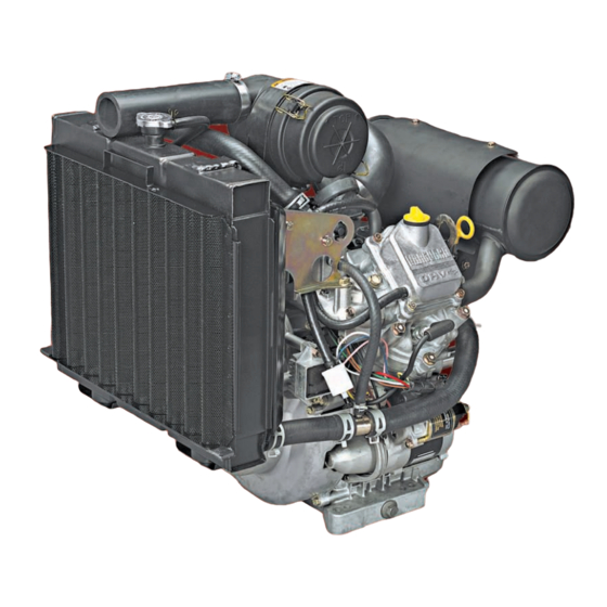
Page 9: Engine Identification
Vanguard Twin-Cylinder OHV Liquid-Cooled Engine Section 1 - General Information ENGINE IDENTIFICATION Oil Fill Cap Fuel Pump Dipstick Muffler (If Equipped) Spark Plug Choke Control 12V Electric Starter Throttle Control (2 Possible Locations) Oil Drain Plug Radiator Reservoir (If Equipped) Fan Belt (If Equipped) Oil Filter Fuel Filter... -
Page 10: Maintenance Schedule
Vanguard Twin-Cylinder OHV Liquid-Cooled Engine Section 1 - General Information MAINTENANCE SCHEDULE Daily 50 Hours 100 Hours 250 Hours 600 Hours Yearly Check Oil Level Check For Oil Leaks Change Oil Change Oil Filter Check Coolant Change X*** Coolant Check Fan Belt Clean Air Filter... -
Page 11: Fuel And Oil Recomendations
Vanguard Twin-Cylinder OHV Liquid-Cooled Engine Section 1 - General Information FUEL AND OIL RECOMENDATIONS Gasoline Use clean, fresh, unleaded gasoline. Leaded gasoline may be used if unleaded is not available. A minimum of 85 octane is recommended. The use of unleaded gasoline results in fewer combustion deposits and longer valve life. -
Page 12: Changing Oil And Oil Filter
Vanguard Twin-Cylinder OHV Liquid-Cooled Engine Section 1 - General Information CHANGING OIL AND OIL FILTER 9. Replace oil fill cap and dipstick. 10. Start and run engine to check for oil leaks. Change oil and filter after first fifty (50) hours of operation. -
Page 13: Cleaning Debris
Vanguard Twin-Cylinder OHV Liquid-Cooled Engine Section 1 - General Information Normal coolant temperature gauge (if equipped) should 1. Loosen bolt and bolt read between 175° and 195° F (80° and 90° C) when 2. Fit torque wrench in the square hole located in the engine is running. -
Page 14: Replace Spark Plug
Vanguard Twin-Cylinder OHV Liquid-Cooled Engine Section 1 - General Information REPLACE SPARK PLUG bore to wear quickly. As the rings and cylinder bore become worn, these abrasive particles enter the crankcase and contaminate the oil, forming an abrasive Replace spark plugs every year. Replace spark plugs if mixture which will cause wear on all of the internal electrodes are burned away, or the porcelain is cracked. - Page 15 Vanguard Twin-Cylinder OHV Liquid-Cooled Engine Section 1 - General Information Page 10...
-
Page 16: Troubleshooting
Vanguard Twin-Cylinder OHV Liquid-Cooled Engine Section 2 - Troubleshooting SECTION 2 3. If starter cranks, there is a problem with the key switch or wiring. TROUBLESHOOTING GENERAL INFORMATION Most complaints concerning engine operation can be classified as one or a combination of the following: 1. -
Page 17: Starter Current Draw Test
Vanguard Twin-Cylinder OHV Liquid-Cooled Engine Section 2 - Troubleshooting STARTER CURRENT DRAW TEST 5. A fully charged 12 volt battery. Testing Starter IMPORTANT : When making the starter current draw NOTE : To prevent engine from starting, remove test make sure that all parasitic load is removed from the spark plug wires from spark plugs and ground engine and that engine has the correct viscosity oil. -
Page 18: No Load Starter Current Draw Test
Vanguard Twin-Cylinder OHV Liquid-Cooled Engine Section 2 - Troubleshooting NO LOAD STARTER CURRENT DRAW 3. Attach negative battery cable to a good ground such as drive housing. TEST 4. Attach positive battery cable to battery terminal on solenoid. Remove starter motor. 5. - Page 19 Vanguard Twin-Cylinder OHV Liquid-Cooled Engine Section 2 - Troubleshooting Check Ignition (With Engine Starter) Check Ignition (Engine Running) With spark plugs installed, attach a ignition tester If engine runs but misses during operation, a quick check #19368 to each spark plug lead and ground the other end of the to determine if ignition is or is not at fault can be made by tester as shown in Fig.12.
- Page 20 Vanguard Twin-Cylinder OHV Liquid-Cooled Engine Section 2 - Troubleshooting DIODE FAILURE DIAGNOSTIC TABLE Ground Wire Harness Diode Diode Fig. 14 Equipment If miss continues: Switch The problem may be carburetion or compression related. See Check Carburetion and/or Cylinder Balance Test and Cylinder Leakdown Test.
-
Page 21: Check Carburetion
Vanguard Twin-Cylinder OHV Liquid-Cooled Engine Section 2 - Troubleshooting If meter “Beeps” once, diode is OK. If plugs are dry, look for: If meter makes a continuous tone, diode is defective 1. Leaking carburetor or intake manifold mounting (shorted). Replace ground harness. gaskets If meter displays “OL,”... -
Page 22: Fuel Pump - General Information
Vanguard Twin-Cylinder OHV Liquid-Cooled Engine Section 2 - Troubleshooting Testing Equipment Wiring 4. If solenoid does not “click”, it is defective. Replace. 1. With keyswitch in position, disconnect solenoid wire (GRAY WIRE) from engine wiring harness connector (WHITE WIRE). 2. Insert red meter test lead into equipment side of wiring harness connector (WHITE WIRE) , Fig. -
Page 23: Cylinder Balance Test
Vanguard Twin-Cylinder OHV Liquid-Cooled Engine Section 2 - Troubleshooting CYLINDER BALANCE TEST If the engine is hard starting, runs rough, misses or lacks power, perform a cylinder balance test to determine whether both cylinders are operating to their full potential. Tools Required 1. -
Page 24: Cylinder Leakdown Test
Vanguard Twin-Cylinder OHV Liquid-Cooled Engine Section 2 - Troubleshooting there will be no RPM loss. When the other cylinder is because compression components are not at normal grounded out the engine will stop. operating temperatures. NOTE 2. Remove spark plugs from engine. Disconnect air : A twin cylinder engine will run well on cleaner tube and crankcase breather tube at one cylinder as long as the power required for... - Page 25 Vanguard Twin-Cylinder OHV Liquid-Cooled Engine Section 2 - Troubleshooting 9. Listen for air leaking from the cylinder head 5. Pull the regulator adjustment knob out and gasket, carburetor, exhaust system and the turn knob counterclockwise as far as it will go, Fig. crankcase breather tube.
-
Page 26: Checking Cooling System
Vanguard Twin-Cylinder OHV Liquid-Cooled Engine Section 2 - Troubleshooting 11. Disconnect outlet hose from tester before a. Coolant level must be no more than 1 in. (.25 removing from spark plug hole. mm) below bottom of filler neck. 12. Repeat test for other cylinder. The variation between the two cylinders should be less than 20%. -
Page 27: Check Oil Pressure Switch
Vanguard Twin-Cylinder OHV Liquid-Cooled Engine Section 2 - Troubleshooting 5. Remove thermostat from water and allow it to cool. a. Thermostat should close fully. Fig. 26 The water pump seal is replaceable. See Section 4. Fig. 27 If system does not maintain pressure and no leaks are evident externally, there may be an internal leak such as CHECK OIL PRESSURE SWITCH a blown head gasket, warped cylinder head or cylinder... -
Page 28: Check Oil Pressure
Vanguard Twin-Cylinder OHV Liquid-Cooled Engine Section 2 - Troubleshooting CHECK OIL PRESSURE CHARGING SYSTEM 1. Oil level must be between the The engine is equipped with a 20 amp regulated FULL mark on dipstick. If oil level is low, check for leaks alternator system that provides AC current through two and add to mark. - Page 29 Vanguard Twin-Cylinder OHV Liquid-Cooled Engine Section 2 - Troubleshooting 4. Attach test lead probe to DC output terminal CAUTION : Attach meter test leads to AC output in white connector (red wire), Fig.31. terminals in white connector (yellow wires) BEFORE STARTING ENGINE.
-
Page 30: Battery Information
Vanguard Twin-Cylinder OHV Liquid-Cooled Engine Section 2 - Troubleshooting 4. Rotate selector to position. Fig. 32 5. With the engine running at 3600 RPM, the output Battery Installation: should be: 1. Before installing battery, connect all equipment to * 3 - 20 Amps - 20 Amp System be operated. -
Page 31: Equipment Affecting Engine Operation
Vanguard Twin-Cylinder OHV Liquid-Cooled Engine Section 2 - Troubleshooting 3. With battery fully charged, check specific gravity 50 Amp. Hr. -15° F (-26° C) or higher readings of each cell with a Battery Hydrometer Battery Cable Recommendations and record readings, Fig. 33. All readings should These cable sizes are based on total length of cable be above (compensating for temperature). -
Page 32: Engine Disassembly
Vanguard Twin-Cylinder OHV Liquid-Cooled Engine Section 3 - Engine Disassembly SECTION 3 2. Disconnect by-pass hose at thermostat housing. ENGINE DISASSEMBLY GENERAL INFORMATION 1. Disconnect battery cables at battery. 2. Disconnect throttle and choke cables. 3. Drain oil and remove oil filter. 4. -
Page 33: Disconnect Fuel Lines
Vanguard Twin-Cylinder OHV Liquid-Cooled Engine Section 3 - Engine Disassembly DISCONNECT FUEL LINES 3. Remove flywheel housing , Fig. 39. 1. Disconnect fuel line from pump to carburetor fuel pump pulse line at valve cover , and fuel inlet line at fuel filter , Fig. -
Page 34: Remove Carburetor
Vanguard Twin-Cylinder OHV Liquid-Cooled Engine Section 3 - Engine Disassembly REMOVE CARBURETOR 6. Remove fan adjustment bracket , Fig. 41. 1. Remove air cleaner assembly. 2. Disconnect throttle link and spring at carburetor , Fig. 43. Fig. 41 7. Remove fan brackets , Fig. -
Page 35: Remove Starter
Vanguard Twin-Cylinder OHV Liquid-Cooled Engine Section 3 - Engine Disassembly 4. Remove governor control bracket 10. Remove air cleaner elbow screws , Fig. 47, and separate carburetor from intake elbow and air disconnect governor link , Fig. 45. cleaner elbow. Fig. -
Page 36: Remove Intake Manifold
Vanguard Twin-Cylinder OHV Liquid-Cooled Engine Section 3 - Engine Disassembly 6. Tighten puller nuts equally until flywheel loosens, 2. Remove fan belt pulley Fig. 51. Fig. 49 Fig. 51 3. Place flywheel strap wrench, Tool around #19433 flywheel. WARNING : DO NOT strike flywheel with a hard object or a metal tool as this may cause flywheel 4. -
Page 37: Remove Alternator
Vanguard Twin-Cylinder OHV Liquid-Cooled Engine Section 3 - Engine Disassembly REMOVE CYLINDER HEADS 3. Remove breather, Fig. 53. 1. Remove valve covers. 2. Remove rocker arms and pushrods , Fig. NOTE : Mark pushrods so that they can be reassembled in their original position. Fig. -
Page 38: Remove Crankcase Cover
Vanguard Twin-Cylinder OHV Liquid-Cooled Engine Section 3 - Engine Disassembly REMOVE CRANKCASE COVER 4. Remove oil pump screws and oil pump Fig. 59. 1. Remove water pump cover , Fig. 57. 2. Remove water pump impeller Fig. 59 5. Remove governor gear and thrust washer Fig. -
Page 39: Remove Camshaft
Vanguard Twin-Cylinder OHV Liquid-Cooled Engine Section 3 - Engine Disassembly REMOVE CAMSHAFT 2. Repeat for other cylinder. 1. Rotate crankshaft and camshaft until timing marks align, then remove camshaft and tappets, Fig. Fig. 62 3. Remove crankshaft. 4. Remove governor shaft, Fig. 63. Fig. -
Page 40: Engine Overhaul
Vanguard Twin-Cylinder OHV Liquid-Cooled Engine Section 4 - Engine Overhaul SECTION 4 b. If cylinder bore is worn more than .003” (0.076 mm) or more than .0015” (0.038 mm) out of ENGINE OVERHAUL round, it must be resized. CHECK CYLINDER CENTER Check cylinder for cracks or stripped threads. - Page 41 Vanguard Twin-Cylinder OHV Liquid-Cooled Engine Section 4 - Engine Overhaul Honing is done with a variable speed 1/2”, portable drill and a honing fixture. A suitable honing fixture can be made from a 2” X 8” X 16” block of wood. Use three or four crankcase cover mounting screws and fasten cylinder to the honing fixture.
-
Page 42: Bearings
Vanguard Twin-Cylinder OHV Liquid-Cooled Engine Section 4 - Engine Overhaul BEARINGS specification. Be careful not to hone oversize or it will be necessary to resize the cylinder. Check Mag Bearing NOTE : To produce the proper cross hatch finish Check magneto bearing for wear or damage, Fig. 68. use a drill speed of approximately 200 RPM and 40-60 strokes per minute. -
Page 43: Crankshaft
Vanguard Twin-Cylinder OHV Liquid-Cooled Engine Section 4 - Engine Overhaul Check PTO Bearing Check PTO bearing for wear or damage, Fig. 70. Reject Dimension: 1.7765” (45.12 mm) If PTO bearing is worn or damaged, the crankcase cover must be replaced. Fig. - Page 44 Vanguard Twin-Cylinder OHV Liquid-Cooled Engine Section 4 - Engine Overhaul necessary to check pistons and rings since a new Check Piston And Rings oversized piston assembly will be used. If the cylinder is not going to be resized and the piston shows no signs of scoring, the piston should be checked.
- Page 45 Vanguard Twin-Cylinder OHV Liquid-Cooled Engine Section 4 - Engine Overhaul Fig. 76 Fig. 78 3. Check piston pin bore, Fig. 77. 2. Check connecting rod bearings, Fig. 79. Replace if greater than .828” (21.03 mm). NOTE : If crankpin bearing is scored or worn the connecting rod must be replaced.
-
Page 46: Inspection And Repair
Vanguard Twin-Cylinder OHV Liquid-Cooled Engine Section 4 - Engine Overhaul CYLINDER HEAD INSPECTION AND Inspect And Repair 1. Check cylinder head. Be sure all gasket material is REPAIR removed from surfaces before checking. Use a gasket scraper if necessary. Disassemble Cylinder Head a. - Page 47 Vanguard Twin-Cylinder OHV Liquid-Cooled Engine Section 4 - Engine Overhaul Remove Valve Guide b. Turn reamer clockwise through entire guide. c. Keep turning reamer clockwise when 1. Press out old valve guide using bushing driver, removing reamer. Tool , Fig. 84. #19367 d.
-
Page 48: Cylinder Head
Vanguard Twin-Cylinder OHV Liquid-Cooled Engine Section 4 - Engine Overhaul a. Use a 605 cutter to narrow seat from bottom Assemble Cylinder Head and a 155 cutter to narrow seat from top, Fig. 1. Use valve guide driver, Tool and install #19416 new intake valve stem seals, Fig. -
Page 49: Oil Pump
Vanguard Twin-Cylinder OHV Liquid-Cooled Engine Section 4 - Engine Overhaul 3. Place a shop rag or short section of rubber fuel 2. Remove oil pick-up tube and screen assembly line under valves inside combustion chamber to hold valve in place while compressing spring. a. -
Page 50: Replacing Water Pump Seal
Vanguard Twin-Cylinder OHV Liquid-Cooled Engine Section 4 - Engine Overhaul REPLACING WATER PUMP SEAL a. Torque screw to 70 in. lbs. (8.0 Nm). The water pump seal may be replaced without removing the crankcase cover from the engine. The water pump housing and water pump impeller must be removed. -
Page 51: Replacing Starter Solenoid
Vanguard Twin-Cylinder OHV Liquid-Cooled Engine Section 4 - Engine Overhaul 3. Then, carefully drive stud and puller nut the rest of Installing Water Pump Seal the way through seal. 1. Press or drive in new water pump seal until it bottoms with a 32 mm 12 point socket, Fig 100. -
Page 52: Replacing Pinion Gear Assembly
Vanguard Twin-Cylinder OHV Liquid-Cooled Engine Section 4 - Engine Overhaul 4. Engage flats on plunger with fork in drive lever and assemble solenoid to starter, Fig. 102. a. Torque nuts to 70 in. lbs. (8.0 Nm). 5. Install field coil wire and nut. a. - Page 53 Vanguard Twin-Cylinder OHV Liquid-Cooled Engine Section 4 - Engine Overhaul 5. Remove armature and pinion gear with drive lever 9. Remove pinion gear and clutch assembly, Fig. from drive end cap, Fig. 105. 107. Fig. 107 Fig. 105 Clean and inspect helix. If helix is damaged, replace 6.
- Page 54 Vanguard Twin-Cylinder OHV Liquid-Cooled Engine Section 4 - Engine Overhaul Inspect Brushes 3. Attach either test lead to starter housing, Fig. 111. Minimum brush dimension is 1/4” (6.0 mm). If brushes 4. Contact first one, then other brush with other test are worn less than specification, replace the starter lead as shown.
- Page 55 Vanguard Twin-Cylinder OHV Liquid-Cooled Engine Section 4 - Engine Overhaul 3. Assemble starter housing to drive housing, NOTE : Lip on spacer must face bearing in aligning notch 115. drive end cap. NOTCH Fig. 113 Fig. 115 Assemble Starter 1. Assemble drive lever to pinion and install 4.
-
Page 56: Carburetor Inspection And Repair
Vanguard Twin-Cylinder OHV Liquid-Cooled Engine Section 4 - Engine Overhaul 6. Compress springs with needle nose pliers and 10. Install solenoid. insert spring behind brushes. Fig. 117 7. Install brush retainer plate. 8. Assemble rubber seal to starter housing, Fig. 118. a. - Page 57 Vanguard Twin-Cylinder OHV Liquid-Cooled Engine Section 4 - Engine Overhaul 6. Remove idle mixture screws and springs, Fig. 3. Remove fixed main jets 123. NOTE : Carburetor is equipped with a different size fixed main jet for each cylinder, Fig. 121. The carburetor is marked “L”...
- Page 58 Vanguard Twin-Cylinder OHV Liquid-Cooled Engine Section 4 - Engine Overhaul 9. Remove throttle shaft, spacer and seal, Fig. 125. ) to clean carburetor parts and #100041 or 100042 body. 4. When cleaning non-metallic parts (plastic, nylon, MinlonE, etc.), do not leave in commercial carburetor cleaner more than 15 minutes.
- Page 59 Vanguard Twin-Cylinder OHV Liquid-Cooled Engine Section 4 - Engine Overhaul 2. Inspect throttle shaft and choke shaft for wear, IMPORTANT: Install one throttle plate at a time. Check Fig. 128. Make sure bushing hole is circular and throttle shaft for freedom of operation before installing there is no wear.
- Page 60 Vanguard Twin-Cylinder OHV Liquid-Cooled Engine Section 4 - Engine Overhaul 6. Install idle mixture screws and springs. DO NOT 8. Assemble inlet valve to float and install float tighten screws at this time, Fig. 132. assembly, Fig. 134. DO NOT install limiter caps at this time. Fig.
- Page 61 Vanguard Twin-Cylinder OHV Liquid-Cooled Engine Section 4 - Engine Overhaul Page 56...
-
Page 62: Engine Assembly
Vanguard Twin-Cylinder OHV Liquid-Cooled Engine Section 5 - Engine Assembly SECTION 5 Lubricate parts with engine oil and assemble #2 piston and connecting rod, Fig. 138. ENGINE ASSEMBLY 1. Offset casting mark on piston must face flywheel side. INSTALL CRANKSHAFT 2. -
Page 63: Install Piston And Connecting Rod
Vanguard Twin-Cylinder OHV Liquid-Cooled Engine Section 5 - Engine Assembly INSTALL PISTON AND CONNECTING a. Push piston down by hand until connecting rod is seated on crankpin. “OUT 1” CYLINDER #1 NOTCH OR FLYWHEEL “OUT 2” CYLINDER #2 NOTE : Install #1 piston and connecting rod first. CASTING MARK SIDE TOWARD... -
Page 64: Install Camshaft
Vanguard Twin-Cylinder OHV Liquid-Cooled Engine Section 5 - Engine Assembly INSTALL CAMSHAFT 3. Check crankshaft end play. End Play: .004” - .011” (0.09 - 0.26 mm) Lubricate tappets, camshaft journals and lobes with engine oil. Assemble timing gear to crankshaft. 1. -
Page 65: Install Starter
Vanguard Twin-Cylinder OHV Liquid-Cooled Engine Section 5 - Engine Assembly INSTALL STARTER 5. Install water pump cover with new gasket. Torque in sequence shown to , Fig. 90 in. lbs. (10.0 Nm) 147. Install starter and solenoid assembly, Fig. 149. Torque screws to 140 in. -
Page 66: Install Flywheel
Vanguard Twin-Cylinder OHV Liquid-Cooled Engine Section 5 - Engine Assembly INSTALL FLYWHEEL 4. Insert push rods into recess in tappets. 1. Clean flywheel and crankshaft taper. Remove all oil, dirt or grease. 2. Assemble flywheel to crankshaft and align keyways. 3. -
Page 67: Adjust Valve Clearance
Vanguard Twin-Cylinder OHV Liquid-Cooled Engine Section 5 - Engine Assembly ADJUST VALVE CLEARANCE 1. Set No. 1 cylinder at 1/4” (6 mm) past TDC, compression stroke. a. Adjust valves and check. Valve Clearance (Cold) IN and EX .008” (0.2 mm) b. -
Page 68: Install Fan Assembly
Vanguard Twin-Cylinder OHV Liquid-Cooled Engine Section 5 - Engine Assembly INSTALL FAN ASSEMBLY b. Torque pivot screw 125 in. lbs. (14.0 Nm) 1. Install fan brackets, Fig. 157. Torque screws 150 in. lbs. (17.0 Nm) NOTE : Take care not to pinch wires between fan brackets and cylinder. -
Page 69: Install Intake Manifold
Vanguard Twin-Cylinder OHV Liquid-Cooled Engine Section 5 - Engine Assembly 8. Connect regulator-rectifier to alternator. 2. Assemble governor link to governor bracket and install governor control bracket, Fig. 162. Torque screws to 70 in. lbs. (8.0 Nm) Fig. 160 Fig. 162 INSTALL INTAKE MANIFOLD INSTALL CARBURETOR AND INTAKE 1. - Page 70 Vanguard Twin-Cylinder OHV Liquid-Cooled Engine Section 5 - Engine Assembly 1. Assemble air cleaner elbow and carburetor to 5. Assemble governor link to governor control intake elbow with new gaskets, Fig. 164. Torque bracket and install governor control bracket, Fig. screws to 166.
-
Page 71: Adjust Governor
Vanguard Twin-Cylinder OHV Liquid-Cooled Engine Section 5 - Engine Assembly Do Not tighten governor lever nut at this time. Static Governor Adjustment 1. With governor lever nut loose, rotate governor control swivel clockwise as far as it will go (wide open throttle) and hold in this position, Fig. -
Page 72: Install Radiator
Vanguard Twin-Cylinder OHV Liquid-Cooled Engine Section 5 - Engine Assembly INSTALL RADIATOR 3. Install fuel line from pump to carburetor , and fuel pump pulse line at valve cover , Fig. 174. 1. Install fan shroud assembly, Fig. 172. Torque screws to . - Page 73 Vanguard Twin-Cylinder OHV Liquid-Cooled Engine Section 5 - Engine Assembly • The inside band of the mounting bracket has screw, Fig. 178. Torque front screw to 90 in. lbs. (10 Nm) locating tabs that fit into notches in the air cleaner housing.
- Page 74 Vanguard Twin-Cylinder OHV Liquid-Cooled Engine Section 5 - Engine Assembly 8. Install air cleaner cover with arrows facing up, Fig. 180. Fig. 180 Refer to Section 6 for final adjustment procedures. Page 69...
- Page 75 Vanguard Twin-Cylinder OHV Liquid-Cooled Engine Section 5 - Engine Assembly Page 70...
-
Page 76: Final Adjustments And Specifications
Vanguard Twin-Cylinder OHV Liquid-Cooled Engine Section 6 - Final Adjustments & Specifications SECTION 6 Governed Idle VanguardE liquid cooled OHV Twin cylinder engines are FINAL ADJUSTMENTS AND equipped with a governed idle system, Fig. 182. A SPECIFICATIONS throttle restrictor permits the engine to maintain engine speed when a load is applied with the equipment control in the SLOW position. -
Page 77: Carburetor Adjustment
Vanguard Twin-Cylinder OHV Liquid-Cooled Engine Section 6 - Final Adjustments & Specifications CARBURETOR ADJUSTMENT 4. Tighten casing clamp screw. The VanguardE liquid cooled OHV Twin cylinder carburetor fuel mixture adjustment procedure is unique. Perform adjustments exactly in the sequence shown. Initial Adjustment 1. - Page 78 Vanguard Twin-Cylinder OHV Liquid-Cooled Engine Section 6 - Final Adjustments & Specifications The following tools are required when making carburetor 7. Release throttle lever. Note RPM. adjustments. 1. An accurate tachometer, such as Tool #19389 2. Tang bender, Tool #19480 Fig.
- Page 79 Vanguard Twin-Cylinder OHV Liquid-Cooled Engine Section 6 - Final Adjustments & Specifications b. Repeat for other idle mixture valve. 13. Bend tang with Tool to obtain 3600 RPM, #19480 Fig. 192. Fig. 190 Fig. 192 10. With equipment control lever in “SLOW” position and engine running at governed idle RPM, use NOTE : To obtain precise Top No Load speed,...
-
Page 80: Model 473100 Specifications
Vanguard Twin-Cylinder OHV Liquid-Cooled Engine Section 6 - Final Adjustments & Specifications MODEL 473100 SPECIFICATIONS Common Specifications .........005” - .007” (0.13 - 0.18 RMATURE . -
Page 81: Standard And Reject Dimensions
Vanguard Twin-Cylinder OHV Liquid-Cooled Engine Section 6 - Final Adjustments & Specifications Standard And Reject Dimensions ESCRIPTION TANDARD IMENSION EJECT IMENSION YLINDER ....3.190” (81.02 ) . -
Page 82: Engine Harness
Vanguard Twin-Cylinder OHV Liquid-Cooled Engine Section 6 - Final Adjustments & Specifications ENGINE HARNESS Page 77... - Page 83 Vanguard Twin-Cylinder OHV Liquid-Cooled Engine Section 6 - Final Adjustments & Specifications Page 78...
- Page 84 Vanguard Twin-Cylinder OHV Liquid-Cooled Engine Section 6 - Final Adjustments & Specifications Page 79...
- Page 85 Vanguard Twin-Cylinder OHV Liquid-Cooled Engine Section 6 - Final Adjustments & Specifications Page 80...
Need help?
Do you have a question about the 272147 and is the answer not in the manual?
Questions and answers
I want to let you know that you have the wrong manual provided for #272147. You have #275429 in its place. The link is https://www.manualslib.com/manual/1051744/Briggs-And-Stratton-272147.html#manual.