Table of Contents
Advertisement
Quick Links
Download this manual
See also:
Instruction Manual
Advertisement
Table of Contents

Related Manuals for Briggs & Stratton 276535


Summary of Contents for Briggs & Stratton 276535
- Page 1 2-Cycle Snow Engine 2-CYCLE SNOW ENGINE REPAIR MANUAL MANUAL NUMBER: 276535...
-
Page 2: 2-Cycle Snow Engine
2-Cycle Snow Engine SAFETY INFORMATION • Prior to work, read and understand the section(s) of this manual that pertain to the job. Follow all safety The Briggs & Stratton engine is made of the finest warnings. material in a state-of-the-art manufacturing facility. •... - Page 3 2-Cycle Snow Engine...
- Page 4 2-Cycle Snow Engine...
-
Page 5: Table Of Contents
2-Cycle Snow Engine Table of Contents 2-CYCLE SNOW ENGINE SECTION 3 REPAIR MANUAL ........0 ENGINE DISASSEMBLY ......9 REMOVE SHROUD ........9 SAFETY INFORMATION ......i REMOVE CARBURETOR ......9 In The Interest Of Safety ....... i REMOVE FLYWHEEL ........10 REMOVE OPTIONAL 120V STARTER ..10 SECTION 1 REMOVE MUFFLER ........10 GENERAL INFORMATION ....... - Page 6 2-Cycle Snow Engine Table of Contents INSTALL PISTON AND CONNECTING ROD ........22 INSTALL CONNECTING ROD BEARINGS 23 INSTALL CRANKSHAFT AND CONNECTING ROD ........23 INSTALL OIL SEALS ........24 INSTALL CRANKCASE COVER ....25 INSTALL CYLINDER HEAD .......25 INSTALL IGNITION COIL AND FLYWHEEL ..........25 INSTALL AIR VANE AND GOVERNOR ..26 INSTALL INTAKE MANIFOLD AND CARBURETOR ..........27...
-
Page 7: General Information
2-Cycle Snow Engine Section 1 - General Information SECTION 1 compresses the fuel mixture (Item Figure 2) that is on the bottom side of the piston in the crankcase. GENERAL INFORMATION TWO-CYCLE ENGINE THEORY In a piston-ported engine, the fuel mixture enters the crankcase through a port that comes directly from the carburetor (commonly referred to as a “third port”), See item... -
Page 8: Ignition Coil Operation
2-Cycle Snow Engine Section 1 - General Information port. As it continues, it compresses the fuel mixture in voltage is converted by a rectifier into a DC signal, which is then stored in a capacitor (Figure 6). the combustion chamber (Item Figure 4). -
Page 9: Rewind Starter
2-Cycle Snow Engine Section 1 - General Information REWIND STARTER At slower speeds, the flywheel magnet induces a smaller charge in the trigger coil. This action triggers the (SCR), enabling easier starting in a “retarded firing position” The rewind starter operates through a retainer/friction -about 5°... -
Page 10: Replace Spark Plug
2-Cycle Snow Engine Section 1 - General Information REPLACE SPARK PLUG 2. Inspect exhaust port (Figure 13). If cleaning is necessary, rotate piston to cover exhaust port, and scrape carbon from exhaust port area. Use Replace spark plug every year. Replace spark plug if wood only to clean this area. -
Page 11: Troubleshooting
2-Cycle Snow Engine Section 2 - Troubleshooting SECTION 2 observed at the tester gap, you may assume the ignition system is functioning satisfactorily. TROUBLESHOOTING GENERAL TROUBLESHOOTING INFORMATION Most complaints concerning engine operation can be classified as one or a combination of the following: •... -
Page 12: Check Carburetion
2-Cycle Snow Engine Section 2 - Troubleshooting when the engine is running. If the spark looks good in the Check Compression tester but the engine misses, try a new spark plug. Connect spark plug wire to long terminal of tester, Tool and ground tester to engine with alligator clip. -
Page 13: Hard Starting, Kickback, Or Will Not Start
2-Cycle Snow Engine Section 2 - Troubleshooting Hard Starting, Kickback, or Will Not Start • Loose drive adapter(s) - Pulleys and adapters must be tight to shaft. Also, check for partially sheared flywheel key. • Starting under load - ensure the unit is not engaged when engine is started;... - Page 14 2-Cycle Snow Engine Section 2 - Troubleshooting Page 8...
-
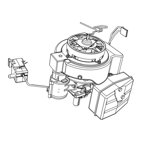
Page 15: Engine Disassembly
2-Cycle Snow Engine Section 3 - Engine Disassembly SECTION 3 3. Slide the air vane from its mounting bracket shown (Figure 18). ENGINE DISASSEMBLY REMOVE SHROUD 1. Disconnect spark plug wire. 2. Remove the two screws that attach the shroud to the base (Figure 17). -
Page 16: Remove Flywheel
2-Cycle Snow Engine Section 3 - Engine Disassembly REMOVE FLYWHEEL REMOVE OPTIONAL 120V STARTER 1. Remove flywheel nut and starter cup (Figure 20). 1. Remove the starter switch, the bolt holding the wire clip, and the two bolts which mount the starter to the engine (Figure 22). -
Page 17: Remove Ignition Module
2-Cycle Snow Engine Section 3 - Engine Disassembly REMOVE IGNITION MODULE 5. Remove the connecting rod cap and the split bearing liner. 1. Remove the two bolts that hold the ignition module to the head (Figure 24). 0720-013 Fig. 26 The needle roller bearings are under the split bearing Fig. - Page 18 2-Cycle Snow Engine Section 3 - Engine Disassembly 9. Remove the two studs and two nuts (Figure 28) retaining the cylinder head to the block. Remove the head and discard the head gasket. 720-008 Fig. 28 Page 12...
-
Page 19: Engine Overhaul
2-Cycle Snow Engine Section 4 - Engine Overhaul SECTION 4 Bearings 1. Check ball bearings for wear and freedom of ENGINE OVERHAUL movement; replace if questionable. Crankcase ENGINE INSPECTION & REPAIR 1. Inspect the crankcase for cracks or any other indication of damage. -
Page 20: Piston And Rings
2-Cycle Snow Engine Section 4 - Engine Overhaul Piston And Rings 7. Check piston diameter using a dial caliper . Replace piston if diameter is less than (#19199) 1. Insert new rings into cylinder bore approximately 2.4935 in. (63.33mm) 1” (25mm). 2. -
Page 21: Carburetor Disassembly
2-Cycle Snow Engine Section 4 - Engine Overhaul CARBURETOR DISASSEMBLY 4. Using needle nose pliers, gently pull the choke plate from the choke shaft (Figure 40). Note the orientation of the small protrusions on the choke plate as you pull it out. NOTE : The exterior of the carburetor should be cleaned before removal from the engine. - Page 22 2-Cycle Snow Engine Section 4 - Engine Overhaul 6. Remove the decal on the side of the carburetor 8. Remove the float hinge pin , the inlet valve and unscrew the pilot jet (Figure 42). needle assembly (with its clip) , and the float (Figure 44).
-
Page 23: Carburetor Cleaning & Inspection
2-Cycle Snow Engine Section 4 - Engine Overhaul install the nozzle assembly into the carburetor Unscrew the high speed jet from the nozzle body (Figure 47). Torque to 25 lb-in (Figure 46). Do not remove the nozzle from the carburetor body. Fig. - Page 24 2-Cycle Snow Engine Section 4 - Engine Overhaul 5. Apply one drop of or equivalent to normal position. Apply pump pressure to Loctite 242™ 5 psi Needle and seat should hold this (34.5kp). the seat threads , and install a new brass inlet pressure for 10 to 15 seconds (Figure 51).
- Page 25 2-Cycle Snow Engine Section 4 - Engine Overhaul 14. Install the choke shaft into the carburetor body as 12. Install the throttle shaft into the carburetor shown in figure 55. body as shown (Figure 53). Fig. 53 Fig. 55 15. Push the choke plate into the choke shaft 13.
-
Page 26: Rewind Starter Replacement
2-Cycle Snow Engine Section 4 - Engine Overhaul REWIND STARTER REPLACEMENT 6. Install starter handle as shown in figure 58. Except for the rope, the rewind starter parts are not serviceable. If damage or wear occurs, the complete assembly must be replaced using the hardware included with the new rewind starter. -
Page 27: Engine Assembly
2-Cycle Snow Engine Section 5 - Engine Assembly SECTION 5 Engine Model 84130 & 84230 ENGINE ASSEMBLY ASSEMBLE PISTON AND CONNECTING ROD Lubricate piston pin with 2 cycle engine oil. 1. Install one piston pin retainer. 2. Insert piston pin through opposite side of piston, through connecting rod until pin contacts pin retainer. -
Page 28: Install Piston And Connecting Rod
2-Cycle Snow Engine Section 5 - Engine Assembly 1. Lubricate piston and rings with engine oil. NOTE : On engine models 84230 and 84330 the transfer ports in the piston skirt must align with 2. Align ring gaps with retainers in ring grooves the “finger ports”... -
Page 29: Install Connecting Rod Bearings
2-Cycle Snow Engine Section 5 - Engine Assembly 2. Lubricate cylinder bore and install piston and the paper and wrap needles around the crank pin with connecting rod assembly making sure that mark the wax towards the crankpin. Wax will hold needles in on piston faces PTO side of engine (Figure 65). -
Page 30: Install Oil Seals
2-Cycle Snow Engine Section 5 - Engine Assembly 4. Torque rod screws to 6. Install snap ring into groove behind PTO ball 70 lb-in. (8.0 Nm) (Figure 68). bearing. Push down on snap ring so that it is seated in its groove (Figure 70). Fig. -
Page 31: Install Crankcase Cover
2-Cycle Snow Engine Section 5 - Engine Assembly INSTALL CRANKCASE COVER INSTALL CYLINDER HEAD 1. Install cylinder head with new gasket (Figure 73). NOTE : The crankcase halves are a matched Ensure studded head bolts face MAG side of assembly and cannot be interchanged between engine. -
Page 32: Install Air Vane And Governor
2-Cycle Snow Engine Section 5 - Engine Assembly INSTALL AIR VANE AND GOVERNOR 3. Torque flywheel nut to 33 lb-ft. (44.7 Nm) 4. Rotate flywheel so that magnet is away from coil mounting area. 1. Install air vane governor bracket to cylinder (Figure 77). -
Page 33: Install Intake Manifold And Carburetor
2-Cycle Snow Engine Section 5 - Engine Assembly INSTALL INTAKE MANIFOLD AND CARBURETOR 1. Install intake manifold with new gasket (Figure 79). Torque screws to 60 lb-in. (7.0 Nm) 2. Assemble carburetor mounting nuts to manifold and install rubber band retainer (later models have tapped holes instead of nuts). -
Page 34: Install Muffler
2-Cycle Snow Engine Section 5 - Engine Assembly INSTALL MUFFLER 4. Assemble ground wire, flat washers and locknuts (Figure 85). 1. Install muffler with new gasket (Figure 83). a. Torque screws to 80 ib-in. (9.0 Nm) Fig. 83 Fig. 85 INSTALL BLOWER HOUSING 5. -
Page 35: Final Adjustments & Specifications
2-Cycle Snow Engine Section 6 - Final Adjustments & Specifications SECTION 6 FINAL ADJUSTMENTS & SPECIFICATIONS GOVERNOR ADJUSTMENTS The governor is adjusted by bending the bracket that the governor spring is attached to (Figure 87). See specification page for proper speeds. Fig. -
Page 36: Specifications
2-Cycle Snow Engine Section 6 - Final Adjustments & Specifications SPECIFICATIONS Fastener Specifications ....W ......T ESCRIPTION RENCH OCKET... -
Page 37: Standard And Reject Dimensions
2-Cycle Snow Engine Section 6 - Final Adjustments & Specifications STANDARD AND REJECT DIMENSIONS ESCRIPTION TANDARD IMENSION EJECT IMENSION ....2.4995” - 2.5005” (63.48 - 63.51 ) . - Page 38 2-Cycle Snow Engine Section 6 - Final Adjustments & Specifications Page 32...
Need help?
Do you have a question about the 276535 and is the answer not in the manual?
Questions and answers