Table of Contents
Advertisement
Advertisement
Table of Contents

Subscribe to Our Youtube Channel
Related Manuals for MTU 12 V 4000 L62


Summary of Contents for MTU 12 V 4000 L62
-
Page 1: Operating Instructions
Operating Instructions Gas engine 12 V 4000 L62 16 V 4000 L62 MS150033/04E... - Page 2 This Publication is protected by copyright and may not be used in any way whether in whole or in part without the prior written permission of MTU Friedrichshafen GmbH. This restriction also applies to copyright, distribution, translation, micro‐ filming and storage or processing on electronic systems including data bases and online services.
-
Page 3: Table Of Contents
6.2.1 Oil separator – Filter replacement 2.5 Technical Data 2.5.1 Runtimes at partial load 6.3 Ignition System 2.5.2 12 V 4000 L62, 16 V 4000 L62 engine data, 6.3.1 Ignition system – Ignition timing check fuel optimized (TA-Luft) 6.3.2 Spark plug connector – Replacement 2.5.3 12V 4000 L62, 16V 4000 L62 engine data,... - Page 4 7 Appendix A 6.9.2 Engine coolant – Change 6.9.3 Engine coolant – Draining 7.1 Abbreviations 6.9.4 Engine coolant – Filling 7.2 MTU Onsite Energy contact / service 6.9.5 Vent line of engine coolant circuit – partner Replacement 6.10 Low-Temperature Circuit 6.10.1 Mixture coolant level - Check...
-
Page 5: Safety
Correct use also includes observation of and compliance with the maintenance specifications. Modifications or conversions Unauthorized modifications to the engine represent a safety risk. MTU will accept no liability or warranty claims for any damage caused by unauthorized modifications or conversions. Spare parts Only genuine MTU spare parts must be used to replace components or assemblies. -
Page 6: Personnel And Organizational Requirements
1.2 Personnel and organizational requirements Personnel requirements All work on the engine shall be carried out by trained and qualified personnel only. The specified legal minimum age must be observed. The operator must specify the responsibilities of the operating, maintenance and repair personnel. Organizational measures This publication must be issued to all personnel involved in operation, maintenance, repair or transporta‐... -
Page 7: Transport
Only set down engine on a firm, level surface. Make sure that the consistency and load-bearing capacity of the ground or support surface is adequate. Never set an engine down on the oil pan unless expressively authorized to do so by MTU on a case-to- case basis. -
Page 8: Safety Regulations For Startup And Operation
Safety precautions when putting the equipment into operation Prior to initial operation of the assembly or plant, install the assembly or unit according to the specifica‐ tions and check the installation according to the MTU specifications. Before putting the device or plant into operation, always ensure: •... -
Page 9: Safety Requirements For Maintenance And Repair Work
1.5 Safety requirements for maintenance and repair work Safety requirements for maintenance and repair work Maintenance and repair work may only be carried out by authorized, qualified personnel. All work on gas-carrying components must be carried out by authorized, specialized companies. Installation and connection of the gas supply must only be carried out by a specialized company with staff that has been trained and authorized for this task. - Page 10 Do not use the assembly or plant as a ground terminal. Never place the welding cable across or near wiring harnesses of MTU plants. The welding current may otherwise induce an interference voltage in the wiring harnesses which could damage the electrical sys‐...
- Page 11 Only tighten union nuts of connectors with connector pliers. On completion of all repair work, the device or system must undergo a function check. Before replacement, ensure that spare parts are correctly stored, i.e. in particular, protected against moisture. Defective electronic components and assemblies must be suitably packed when dispatched for repair, i.e.
-
Page 12: Fluids And Lubricants, Fire Prevention And Environmental Protection
Only fuels of the specified quality required to achieve emission limits must be used. Dispose of used fluids, lubricants and filters in accordance with local regulations. Batteries can be returned within the EU to MTU FN / MTU Onsite Energy free of charge for correct recy‐ cling/disposal. - Page 13 Procedure in the case of accidental release of combustible gas: • Seal point of gas escape! • Remove ignition sources! • Cordon off danger zone. • Ensure sufficient ventilation! • Do not enter danger zone before measurements have confirmed that gas concentration is not hazard‐ ous.
- Page 14 • Pay special attention to the pressure level in the compressed air network and pressure vessel! • Assemblies or plants to be connected must either be designed for this pressure, or, if the permitted pressure for the connecting elements is lower than the pressure required, a pressure reducing valve and safety valve (set to permitted pressure) must form an intermediate connection.
-
Page 15: Conventions For Safety Instructions In The Text
1.7 Conventions for safety instructions in the text DANGER In the event of immediate danger. Consequences: Death or serious injury • Remedial action WARNING In the event of potentially dangerous situations. Consequences: Death or serious injury • Remedial action CAUTION In the event of dangerous situations. -
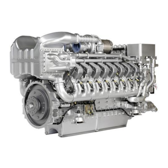
Page 16: Product Summary
2 Product Summary 2.1 Engine – Overview 1 Throttle, A-side 6 Engine lifting equipment 11 Starter 2 Engine governor/engine 7 Capacitor ignition sys‐ 12 Flywheel monitoring KS Driving end 3 Air filter/air inlet 8 Engine mounting brack‐ 4 Mixture cooler et, free end 5 Exhaust turbocharger 9 Oil pan... - Page 17 1 Crankcase breather, oil 7 Spark plug 13 Engine coolant inlet separator 8 Cylinder head cover connection 2 Exhaust gas outlet con‐ 9 Cylinder head 14 Engine oil heat ex‐ nection 10 Engine oil sampling con‐ changer 3 Gas dosing and mixing nection 15 Engine coolant outlet unit (Tecjet)
-
Page 18: Engine Side And Cylinder Designations
2.2 Engine side and cylinder designations Engine sides are always designated as viewed from the driving end (KS). The cylinders of the left engine side are designated "A" and those of the right side "B" (as per DIN ISO 1204). The cylinders of each bank are numbered consecutively, starting with No. 1 at the driving end. Other components are numbered in the same way, i.e. -
Page 19: Engine - Main Dimensions
2.3 Engine – Main dimensions Main engine dimensions Deviations from illustrations are insignificant. Also valid for 16V engines. Length (A) for 12V approx. 2825 mm Length (A) for 16V approx. 3348 mm Width (B) for 12V approx. 1607 mm Width (B) for 16V approx. -
Page 20: Ignition Order
2.4 Ignition order Ignition order 12 V A1-B2-A5-B4-A3-B1-A6-B5-A2-B3-A4-B6 16 V A1-A7-B4-B6-A4-B8-A2-A8-B3-B5-A3-A5-B2-A6-B1-B7 20 | Product Summary | MS150033/04E 2012-07... -
Page 21: Technical Data
2.5 Technical Data 2.5.1 Runtimes at partial load Gas engines were designed and optimized for continuous operation at 100 % load. The following restrictions apply to ensure maximum operational availability of the engine plant and to re‐ duce maintenance to a minimum: Power, referenced to nominal Recommended maximum run‐... -
Page 22: 4000 L62, 16 V 4000 L62 Engine Data, Fuel Optimized (Ta-Luft)
2.5.2 12 V 4000 L62, 16 V 4000 L62 engine data, fuel optimized (TA-Luft) Explanation: DL Reference value: Continuous power BL Reference value: Fuel stop power A Design value G Guaranteed value R Guideline value L Limit value, up to which the engine can be operated, without change (e.g. of power setting) - Page 23 Consumption Number of cylinders Lube oil consumption after 1000 h runtime g/kWh Table 5: Consumption Model-related data (basic design) Number of cylinders Operating method: Four-stroke cycle, Otto engine, single-acting Combustion method: Mixture charging, spark ignition Number of cylinders Cylinder arrangement: V angle Degrees (°) Bore...
- Page 24 Coolant system (LT circuit) Number of cylinders Coolant temperature before mixture cooler (at engine connec‐ °C tion: inlet from cooling equipment (w/o antifreeze) Coolant antifreeze content, max. Coolant pump: Volumetric flow m³/h Pressure in cooling system, max. Pressure loss over mixture cooler (at nominal flow rate 8.56) Table 8: Coolant system (LT circuit) Lube oil system Number of cylinders...
- Page 25 Starting (electric) Number of cylinders Starter, rated power (standard design) 2 x 9 Rated starter voltage (standard design) Starter, current consumption, max. (standard design) 2500 2 x 2500 Starting-attempt duration, max. Number of teeth on starter ring gear Table 12: Starting (electric) Capacities Number of cylinders Engine coolant capacity, engine side (without cooling equip‐...
-
Page 26: 4000 L62, 16V 4000 L62 Engine Data, Emissions-Optimized (1/2 Ta-Luft)
2.5.3 12V 4000 L62, 16V 4000 L62 engine data, emissions-optimized (1/2 TA-Luft) Explanation: DL Reference value: Continuous power BL Reference value: Fuel stop power A Design value G Guaranteed value R Guideline value L Limit value, up to which the engine can be operated, without change (e.g. of power setting) N Not yet defined value - Not applicable X Applicable... - Page 27 Consumption Number of cylinders Lube oil consumption after 1000 h runtime g/kWh Table 20: Consumption Model-related data (basic design) Number of cylinders Operating method: Four-stroke cycle, Otto engine, single-acting Combustion method: Mixture charging, spark ignition Number of cylinders Cylinder arrangement: V angle Degrees (°) Bore...
- Page 28 Coolant system (LT circuit) Number of cylinders Coolant temperature before mixture cooler (at engine connec‐ °C tion: inlet from cooling equipment (w/o antifreeze) Coolant antifreeze content, max. Coolant pump: Volumetric flow m³/h Pressure in cooling system, max. Pressure loss over mixture cooler (at nominal flow rate 8.56) Table 23: Coolant system (LT circuit) Lube oil system Number of cylinders...
- Page 29 Starting (electric) Number of cylinders Starter, rated power (standard design) 2 x 9 Rated starter voltage (standard design) Starter, current consumption, max. (standard design) 2500 2 x 2500 Starting-attempt duration, max. Number of teeth on starter ring gear Table 27: Starting (electric) Capacities Number of cylinders Engine coolant capacity, engine side (without cooling equip‐...
-
Page 30: Monitoring, Control And Regulation Equipment
2.6 Monitoring, Control and Regulation Equipment 2.6.1 Gas engine phase 3 system – Overview Overview 1 Genset system 5 Engine monitoring 9 Knock module 2 Engine system 6 NOx sensor 10 Gas metering unit 3 Genset 7 Compressor bypass 11 Throttles 4 Engine governor 8 Ignition Governing/control/monitoring... - Page 31 Compressor bypass (F-series) • Controls throttle reserve, blocks compressor pumps Ignition system IC922 • Adjusts ignition timing for cylinders Anti-knock control AKR • Controls monitored cylinders with regard to knock characteristics. If knocking is found, the ignition tim‐ ing is retarded on the cylinder in question. If this does not result in an improvement, the power is re‐ duced.
-
Page 32: Control Cabinet Mis - Overview
2.6.2 Control cabinet MIS – Overview Phase 3 gas engine control cabinet MIS – Overview A Control cabinet door, 2 Automatic cutout 6A 5 Automatic cutout 32A external side 3 Relay 6 Automatic cutout 16A B Mounting plate 4 Terminal block 7 Emergency stop (key 1 SAM switch) -
Page 33: Purpose Of The Units
2.6.3 Purpose of the units Engine governor ADEC (ECU 7) Central control and monitoring unit for the engine • Communication with other devices and higher-level systems via CAN bus • Control of throttles (mixture and gas) • Acquisition and evaluation of engine operating states •... - Page 34 Service and Automation Module SAM 1 Module cassette, slots 4 Control keys for Mini Di‐ 7 Connector with spring for additional I/O PIM alog design cards 5 Diagnostic lamp 2 Compact Flash Memory 6 Interface for dialog unit card 3 Display for fault code and Mini Dialog SAM functions •...
- Page 35 Customer interface • 24 binary outputs • 3 PWM outputs • 8 display outputs • 28 channel binary input • 10 analog inputs (e.g. PT100, 4–20 mA, 0-10 V, etc.) • 4 frequency inputs • 1 dialog interface • Extendable with MCS 5 PIM I/O cards CANOpen and SAE-J1939 interface For CANOpen and J1939 interface, a type CCB2 printed circuit board (1) is inserted in slot 3 of the SAM unit.
- Page 36 Monitoring unit for the engine • Acquisition and processing of cylinder exhaust temperatures Self-monitoring 36 | Product Summary | MS150033/04E 2012-07...
-
Page 37: Operation
3.1 Putting the engine into operation after extended out-of- service-periods (>3 months) Preconditions ☑ Engine is stopped and starting disabled. ☑ MTU Fluids and Lubricants Specifications (A001061/..) are available. Putting the engine into operation after extended out-of-service-periods (>3 months) Item Task Engine Depreserve (→... -
Page 38: Putting The Engine Into Operation After Scheduled Out-Of-Service-Period
3.2 Putting the engine into operation after scheduled out-of- service-period Preconditions ☑ Engine shut down and starting disabled. Putting into operation Item Measure Lube oil system Check oil level in oil storage tank (→ Page 156). Coolant circuit Check engine coolant level (→ Page 160); Check mixture coolant level (→... -
Page 39: Control, Starting And Stopping Sequences
3.3 Control, starting and stopping sequences Starting and stopping sequences The start sequence is software-controlled and depends on the place of start command input. To ensure that no mixture is in the engine when ignition is switched on or off, which is a specific require‐ ment for gas engines, special procedures for engine start / stop are specified. -
Page 40: Starting The Engine
3.4 Starting the engine Preconditions ☑ Generator not connected to network ☑ Start interlock is not active. DANGER Unguarded rotating and moving engine components. Risk of serious injury – danger to life! • Before barring or starting the engine, make sure that nobody is in the danger zone. WARNING Engine noise above 85 dB (A). -
Page 41: Operational Checks
3.5 Operational checks DANGER Unguarded rotating and moving engine components. Risk of serious injury – danger to life! • Take special care when working on a running engine. WARNING Engine noise above 85 dB (A). Risk of damage to hearing! •... -
Page 42: Stopping The Engine
3.6 Stopping the engine Preconditions ☑ Generator is not connected to network. CAUTION Stopping the engine when it is running at full load causes extreme stress to the engine. Risk of overheating, damage to components! • Before stopping the engine, operate it at idle speed until operating temperatures decrease and stable values are indicated. -
Page 43: Emergency Stop
3.7 Emergency stop CAUTION An emergency stop causes extreme stress to the engine. Risk of overheating, damage to components! • Initiate emergency stop only in emergency situations. Emergency stop Item Task Emergency stop button Press. • Engine is stopped. Safety measures Item Task Emergency stop button... -
Page 44: After Stopping The Engine - Engine Remains Ready For Operation
3.8 After stopping the engine – Engine remains ready for operation After stopping the engine Item Measure Engine / genset control • Engine is in stop mode. system For engine restart, refer to documentation “Genset control system”. 44 | Operation | MS150033/04E 2012-07... -
Page 45: After Stopping The Engine - Putting The Engine Out Of Operation
If the engine is to remain out of service for more than 1 week, seal the tems engine's air and exhaust sides. If the engine is to remain out of operation for more than 1 month, preserve engine (→ MTU Fluids and Lubricants Specifications A001061/.. ). Starter battery (batteries) Charge regularly (trickle charge). -
Page 46: Maintenance
4 Maintenance 4.1 50-hours check 50-hours check One-time operations to be carried out after the first 50 operating hours of the cylinder head (with a new engine, after installation of new cylinder heads, after component maintenance or extended component maintenance). When installing a cylinder head with run-in mating faces (e.g. -
Page 47: Maintenance Task Reference Table [Ql1]
4.2 Maintenance task reference table [QL1] The maintenance tasks and intervals for this product are defined in the Maintenance Schedule. The Maintenance Schedule is a stand-alone publication. The task numbers in this table provide reference to the maintenance tasks specified in the Maintenance Schedule. -
Page 48: Troubleshooting
5 Troubleshooting 5.1 Fault indication on SAM display General abbreviations used The following general abbreviations are used in the fault message texts: Abbreviation Meaning DL <Number> Default Lost: The device identified by <number> has no connection to the Default CAN bus. RL <number>... - Page 49 Important information about fault messages from the SAM Fault messages from the SAM are represented in the fault code list (→ Page 52). Only persons with a corresponding qualification/training at MTU are allowed to carry out the measures listed below.
- Page 50 OEM (see documentation of the genset manu‐ facturer). Only persons with a corresponding qualification/training at MTU are allowed to carry out the measures listed below. Contact Service should troubleshooting as prescribed in the fault code list prove unsuccessful.
- Page 51 SE No. Fault message text I/O-Module Slot8 Defect Download Server Collision not projected node Device specific error not projected node Device specific error MS150033/04E 2012-07 | Troubleshooting | 51...
-
Page 52: Sam - Fault Messages
5.2 SAM – Fault messages 112222 – HI T-Exhaust Mean Yellow alarm. Initiated by EMU. Cause Corrective action The average value of all 1. Check emission values. individual cylinder exhaust 2. Check ignition timing (→ Page 137). temperatures is too high. 3. - Page 53 112305 – HI T-Exhaust A5 Yellow alarm. Initiated by EMU. Cause Corrective action The exhaust temperature of this 1. Check emission values. cylinder is too high as compared 2. Check ignition timing (→ Page 137). with the average value. 3. Check valve drive (exhaust valves do not close). 112306 –...
- Page 54 112311 – HI T-Exhaust B1 Yellow alarm. Initiated by EMU. Cause Corrective action The exhaust temperature of this 1. Check emission values. cylinder is too high as compared 2. Check ignition timing (→ Page 137). with the average value. 3. Check valve drive (exhaust valves do not close). 112312 –...
- Page 55 112317 – HI T-Exhaust B7 Yellow alarm. Initiated by EMU. Cause Corrective action The exhaust temperature of this 1. Check emission values. cylinder is too high as compared 2. Check ignition timing (→ Page 137). with the average value. 3. Check valve drive (exhaust valves do not close). 112318 –...
- Page 56 112403 – LO T-Exhaust A3 Yellow alarm. Initiated by EMU. Cause Corrective action The exhaust temperature of this 1. Check spark plug. cylinder is too low as compared 2. Check emission values. with the average value. 3. Check ignition timing (→ Page 137). 4.
- Page 57 112408 – LO T-Exhaust A8 Yellow alarm. Initiated by EMU. Cause Corrective action The exhaust temperature of this 1. Check spark plug. cylinder is too low as compared 2. Check emission values. with the average value. 3. Check ignition timing (→ Page 137). 4.
- Page 58 112413 – LO T-Exhaust B3 Yellow alarm. Initiated by EMU. Cause Corrective action The exhaust temperature of this 1. Check spark plug. cylinder is too low as compared 2. Check emission values. with the average value. 3. Check ignition timing (→ Page 137). 4.
- Page 59 112418 – LO T-Exhaust B8 Yellow alarm. Initiated by EMU. Cause Corrective action The exhaust temperature of this 1. Check spark plug. cylinder is too low as compared 2. Check emission values. with the average value. 3. Check ignition timing (→ Page 137). 4.
- Page 60 112504 – HIHI T-Exhaust A4 Red alarm. Initiated by EMU. Cause Corrective action The exhaust temperature of this 1. Check emission values. cylinder is too high as compared 2. Check ignition timing (→ Page 137). with the average value. 3. Check valve drive (exhaust valves do not close). 112505 –...
- Page 61 112510 – HIHI T-Exhaust A10 Red alarm. Initiated by EMU. Cause Corrective action The exhaust temperature of this 1. Check emission values. cylinder is too high as compared 2. Check ignition timing (→ Page 137). with the average value. 3. Check valve drive (exhaust valves do not close). 112511 –...
- Page 62 112516 – HIHI T-Exhaust B6 Red alarm. Initiated by EMU. Cause Corrective action The exhaust temperature of this 1. Check emission values. cylinder is too high as compared 2. Check ignition timing (→ Page 137). with the average value. 3. Check valve drive (exhaust valves do not close). 112517 –...
- Page 63 112602 – LOLO T-Exhaust A2 Red alarm. Initiated by EMU. Cause Corrective action The exhaust temperature of this 1. Check spark plug. cylinder is too low as compared 2. Check emission values. with the average value. 3. Check ignition timing (→ Page 137). 4.
- Page 64 112607 – LOLO T-Exhaust A7 Red alarm. Initiated by EMU. Cause Corrective action The exhaust temperature of this 1. Check spark plug. cylinder is too low as compared 2. Check emission values. with the average value. 3. Check ignition timing (→ Page 137). 4.
- Page 65 112612 – LOLO T-Exhaust B2 Red alarm. Initiated by EMU. Cause Corrective action The exhaust temperature of this 1. Check spark plug. cylinder is too low as compared 2. Check emission values. with the average value. 3. Check ignition timing (→ Page 137). 4.
- Page 66 112617 – LOLO T-Exhaust B7 Red alarm. Initiated by EMU. Cause Corrective action The exhaust temperature of this 1. Check spark plug. cylinder is too low as compared 2. Check emission values. with the average value. 3. Check ignition timing (→ Page 137). 4.
- Page 67 112703 – HIHI T-Exhaust A3 (abs) Red alarm. Initiated by EMU. Cause Corrective action The exhaust temperature of this 1. Check emission values. cylinder is too high. 2. Check ignition timing (→ Page 137). 3. Check valve drive (exhaust valves do not close). 112704 –...
- Page 68 112709 – HIHI T-Exhaust A9 (abs) Red alarm. Initiated by EMU. Cause Corrective action The exhaust temperature of this 1. Check emission values. cylinder is too high. 2. Check ignition timing (→ Page 137). 3. Check valve drive (exhaust valves do not close). 112710 –...
- Page 69 112715 – HIHI T-Exhaust B5 (abs) Red alarm. Initiated by EMU. Cause Corrective action The exhaust temperature of this 1. Check emission values. cylinder is too high. 2. Check ignition timing (→ Page 137). 3. Check valve drive (exhaust valves do not close). 112716 –...
- Page 70 112923 – MD/SD T-Exhaust Red alarm. Initiated by EMU. Cause Corrective action Combined alarm (for details, u Combined alarm (for details, refer to the source alarm). refer to the source alarm). 150176 – Lube Oil Min Red alarm. Initiated by SAM. Cause Corrective action Minimum engine oil level...
- Page 71 150204 – Comm. Lost Mixer (TecJet) Red alarm. Initiated by SAM. Cause Corrective action No communication with mixer 1. Check supply voltage. (TecJet) CAN. 2. Check connecting line. 150352 – SS Release Circuit Breaker Red alarm. Initiated by SAM. Cause Corrective action Circuit breaker release detected.
- Page 72 150402 – LO Oil Refill Yellow alarm. Initiated by SAM. Cause Corrective action No oil replenishment within a u Check oil replenishment system. configurable time. 150403 – AL Oil Refill Error Red alarm. Initiated by SAM. Cause Corrective action After initiation of the alarms 1.
- Page 73 151021 – Warning Hold Position Yellow alarm. Initiated by TecJet. Cause Corrective action Hold position is activated. u Deactivate setting or interrupt serial communication. 151022 – Zero Pressure Detected Yellow alarm. Initiated by TecJet. Cause Corrective action No gas pressure/gas flow u Check gas pressure.
- Page 74 151029 – FGT Fail High Red alarm. Initiated by TecJet. Cause Corrective action Hardware not ready for u Restart TecJet. operation. 151030 – Delta P Fail High Red alarm. Initiated by TecJet. Cause Corrective action Excessive differential pressure 1. Check gas pressure. over TecJet detected.
- Page 75 151038 – Delta P Fail Low Red alarm. Initiated by TecJet. Cause Corrective action Differential pressure at TecJet is u Check TecJet and configuration. below the preset limit value. 151039 – FGP Fail Low Red alarm. Initiated by TecJet. Cause Corrective action Gas pressure before TecJet is u Check TecJet and configuration.
- Page 76 151051 – PWM Duty Cycle High Error Red alarm. Initiated by TecJet. Cause Corrective action PWM signal is beyond the valid 1. Check cabling. range. 2. Check frequency. 3. Check signal. 151052 – Battery Volt Low Error Red alarm. Initiated by TecJet. Cause Corrective action Supply voltage has reached...
- Page 77 151058 – Delta P High Limit Error Red alarm. Initiated by TecJet. Cause Corrective action Hardware not ready for u Restart TecJet. operation. 151059 – FGP High Limit Error Red alarm. Initiated by TecJet. Cause Corrective action Hardware not ready for u Restart TecJet.
- Page 78 152011 – Error Missing Ring Gear Signal Red alarm. Initiated by IC922. Cause Corrective action Crankshaft signal for ignition u Check sensor B13.2, check sensor clearance and cabling, speed 182 teeth missing. replace if necessary. Restart of ignition system required to restart the engine.
- Page 79 152019 – Global Timing out of Range Yellow alarm. Initiated by IC922. Cause Corrective action Specified global ignition timing is u Adjust value. beyond the valid range. 152020 – Unknown Timing or Energy Level Red alarm. Initiated by IC922. Cause Corrective action No global ignition timing and u Check cabling and setting.
- Page 80 152028 – Open Primary, Channel 3 Yellow alarm. Initiated by IC922. Cause Corrective action Ignition energy was not 1. Check cabling to ignition coil. discharged. 2. Check ignition coil. 152029 – Open Primary, Channel 4 Yellow alarm. Initiated by IC922. Cause Corrective action Ignition energy was not...
- Page 81 152035 – Open Primary, Channel 10 Yellow alarm. Initiated by IC922. Cause Corrective action Ignition energy was not 1. Check cabling to ignition coil. discharged. 2. Check ignition coil. 152036 – Open Primary, Channel 11 Yellow alarm. Initiated by IC922. Cause Corrective action Ignition energy was not...
- Page 82 152042 – Open Primary, Channel 17 Yellow alarm. Initiated by IC922. Cause Corrective action Ignition energy was not 1. Check cabling to ignition coil. discharged. 2. Check ignition coil. 152043 – Open Primary, Channel 18 Yellow alarm. Initiated by IC922. Cause Corrective action Ignition energy was not...
- Page 83 152054 – SCR Fault Odd Red alarm. Initiated by IC922. Cause Corrective action Hardware not ready for u Restart ignition system. operation. 152055 – SCR Fault Even Red alarm. Initiated by IC922. Cause Corrective action Hardware not ready for u Restart ignition system. operation.
- Page 84 153104 – Error Camshaft Red alarm. Initiated by antiknock control. Cause Corrective action No signal from camshaft sensor 1. Check cabling. for antiknock control. 2. Check sensor B1.3, replace as necessary. 153111 – Knock Sensor Error A1 Red alarm. Initiated by antiknock control. Cause Corrective action No signal received from this...
- Page 85 153116 – Knock Sensor Error A6 Red alarm. Initiated by antiknock control. Cause Corrective action No signal received from this 1. Check cabling. knock sensor. 2. Check sensor (tightening torque, damage), replace as necessary. 153117 – Knock Sensor Error A7 Red alarm.
- Page 86 153122 – Knock Sensor Error B2 Red alarm. Initiated by antiknock control. Cause Corrective action No signal received from this 1. Check cabling. knock sensor. 2. Check sensor (tightening torque, damage), replace as necessary. 153123 – Knock Sensor Error B3 Red alarm.
- Page 87 153128 – Knock Sensor Error B8 Red alarm. Initiated by antiknock control. Cause Corrective action No signal received from this 1. Check cabling. knock sensor. 2. Check sensor (tightening torque, damage), replace as necessary. 153129 – Knock Sensor Error B9 Red alarm.
- Page 88 153224 – HI Knock Integrator A4 Yellow alarm. Initiated by SAM. Cause Corrective action Readjustment of ignition timing 1. Check emission values. beyond a limit value because 2. Check ignition timing (→ Page 137). knocking was detected in this 3. Check combustion chamber. cylinder.
- Page 89 153229 – HI Knock Integrator A9 Yellow alarm. Initiated by SAM. Cause Corrective action Readjustment of ignition timing 1. Check emission values. beyond a limit value because 2. Check ignition timing (→ Page 137). knocking was detected in this 3. Check combustion chamber. cylinder.
- Page 90 153234 – HI Knock Integrator B4 Yellow alarm. Initiated by SAM. Cause Corrective action Readjustment of ignition timing 1. Check emission values. beyond a limit value because 2. Check ignition timing (→ Page 137). knocking was detected in this 3. Check combustion chamber. cylinder.
- Page 91 153239 – HI Knock Integrator B9 Yellow alarm. Initiated by SAM. Cause Corrective action Readjustment of ignition timing 1. Check emission values. beyond a limit value because 2. Check ignition timing (→ Page 137). knocking was detected in this 3. Check combustion chamber. cylinder.
- Page 92 153244 – HIHI Knock Integrator A4 Red alarm. Initiated by SAM. Cause Corrective action Emergency stop due to knocking 1. Check emission values. detected in this cylinder. 2. Check ignition timing (→ Page 137). 3. Check combustion chamber. 4. Check gas quality if feasible (methane number). 153245 –...
- Page 93 153249 – HIHI Knock Integrator A9 Red alarm. Initiated by SAM. Cause Corrective action Emergency stop due to knocking 1. Check emission values. detected in this cylinder. 2. Check ignition timing (→ Page 137). 3. Check combustion chamber. 4. Check gas quality if feasible (methane number). 153250 –...
- Page 94 153254 – HIHI Knock Integrator B4 Red alarm. Initiated by SAM. Cause Corrective action Emergency stop due to knocking 1. Check emission values. detected in this cylinder. 2. Check ignition timing (→ Page 137). 3. Check combustion chamber. 4. Check gas quality if feasible (methane number). 153255 –...
- Page 95 153259 – HIHI Knock Integrator B9 Red alarm. Initiated by SAM. Cause Corrective action Emergency stop due to knocking 1. Check emission values. detected in this cylinder. 2. Check ignition timing (→ Page 137). 3. Check combustion chamber. 4. Check gas quality if feasible (methane number). 153260 –...
- Page 96 153265 – HI Misfire Integrator A5 Yellow alarm. Initiated by SAM. Cause Corrective action Misfiring was detected in this 1. Check emission values. cylinder. 2. Check spark plug (energy level ignition system). 153266 – HI Misfire Integrator A6 Yellow alarm. Initiated by SAM. Cause Corrective action Misfiring was detected in this...
- Page 97 153272 – HI Misfire Integrator B2 Yellow alarm. Initiated by SAM. Cause Corrective action Misfiring was detected in this 1. Check emission values. cylinder. 2. Check spark plug (energy level ignition system). 153273 – HI Misfire Integrator B3 Yellow alarm. Initiated by SAM. Cause Corrective action Misfiring was detected in this...
- Page 98 153279 – HI Misfire Integrator B9 Yellow alarm. Initiated by SAM. Cause Corrective action Misfiring was detected in this 1. Check emission values. cylinder. 2. Check spark plug (energy level ignition system). 153280 – HI Misfire Integrator B10 Yellow alarm. Initiated by SAM. Cause Corrective action Misfiring was detected in this...
- Page 99 153286 – HIHI Misfire Integrator A6 Red alarm. Initiated by SAM. Cause Corrective action Misfiring was detected in this 1. Check emission values. cylinder. 2. Check spark plug (energy level ignition system). 153287 – HIHI Misfire Integrator A7 Red alarm. Initiated by SAM. Cause Corrective action Misfiring was detected in this...
- Page 100 153293 – HIHI Misfire Integrator B3 Red alarm. Initiated by SAM. Cause Corrective action Misfiring was detected in this 1. Check emission values. cylinder. 2. Check spark plug (energy level ignition system). 153294 – HIHI Misfire Integrator B4 Red alarm. Initiated by SAM. Cause Corrective action Misfiring was detected in this...
- Page 101 153300 – HIHI Misfire Integrator B10 Red alarm. Initiated by SAM. Cause Corrective action Misfiring was detected in this 1. Check emission values. cylinder. 2. Check spark plug (energy level ignition system). MS150033/04E 2012-07 | Troubleshooting | 101...
-
Page 102: Engine Governor - Fault Messages
5.3 Engine governor – Fault messages 015 – LO P-Lube Oil ZKP-Number: Yellow alarm. Associated parameter 2.0100.921 Cause Corrective action Engine oil pressure too low (limit 1. Check oil system, oil heat exchanger. value 1). Lack of engine oil, 2. Replace oil filter (→ Page 159). engine speed too low, oil lines, 3. - Page 103 020 – SS T-Exhaust A ZKP-Number: Yellow alarm. Associated parameter 2.0126.932 Cause Corrective action Exhaust gas temperature (A 1. Check exhaust turbocharger. side) after turbine too high (limit 2. Check ignition timing (→ Page 137). value 2). Incorrect ignition timing, 3.
- Page 104 026 – HI P-Diff-Lube Oil ZKP-Number: Red alarm. Engine shutdown. Associated parameter 2.0154.932 Cause Corrective action Pressure loss via oil filter too 1. Replace oil filter (→ Page 159). high (limit value 2). 2. If this fault message occurs again after unexpectedly short filter runtime, check oil filter for deposits, change oil if required (→...
- Page 105 036 – HI ETC2 Overspeed ZKP-Number: Yellow alarm. Associated parameter 2.3013.931 Cause Corrective action Speed of 1st secondary u Turbocharger speed sensor is not fitted at present. Check ECU turbocharger too high (limit value setting for this input. 037 – SS ETC2 Overspeed ZKP-Number: Red alarm.
- Page 106 053 – HI T-Intake Air ZKP-Number: Yellow alarm. Associated parameter 2.0123.931 Cause Corrective action Intake air temperature too high u Check ventilation system. (limit value 1). 054 – HIHI T-Intake Air ZKP-Number: Yellow alarm. Associated parameter 2.0123.932 Cause Corrective action Intake air temperature too high 1.
- Page 107 063 – HI P-Crank Case ZKP-Number: Yellow alarm. Associated parameter 2.0106.931 Cause Corrective action Crankcase pressure too high 1. Check crank drive: (limit value 1). Restrictor valve in • Crank engine (→ Page 133). crankcase breather is closed too • Endoscope combustion chambers from bottom dead center to much, air filter is defective, oil top dead center.
- Page 108 068 – SS T-Coolant ZKP-Number: Red alarm. Engine shutdown. Associated parameter 2.0120.932 Cause Corrective action Coolant temperature after engine u Check engine coolant circuit. too high (limit value 2). Engine coolant pump failure, volumetric flow too low, air in engine coolant circuit.
- Page 109 091 – SS Release Speed Not Reached ZKP-Number: Red alarm. Start terminated. Associated parameter 2.1090.924 Cause Corrective action The speed (starter 1. Check ignition. DISENGAGE) was not attained, 2. Check gas supply. ignition not working or no gas 3. Check mixture setting. available.
- Page 110 095 – AL Prelubrication Fault ZKP-Number: Red alarm. Start terminated. Associated parameter 2.1090.920 Cause Corrective action Oil priming fault. 1. Check oil pressure, oil temperature, oil level. 2. Check oil priming pump. 104 – AL Eng Hours Counter Defect ZKP-Number: Yellow alarm.
- Page 111 121 – HIHI ECU Supply Voltage ZKP-Number: Red alarm. Associated parameter 2.0140.932 Cause Corrective action Supply voltage too high (limit 1. Check supply voltage. value 2). 2. Check cabling. 122 – HI T-ECU ZKP-Number: Yellow alarm. Associated parameter 2.0132.921 Cause Corrective action Electronics temperature too high u Improve cooling of governor.
- Page 112 180 – AL CAN1 Node Lost ZKP-Number: Yellow alarm. Associated parameter 2.0500.680 Cause Corrective action Bus node (SAM or EMU) lost on u Check operation of nodes and cabling. Busses (CAN bus 1 and CAN bus 1. CAN bus 2) are redundant. 181 –...
- Page 113 184 – AL CAN PU-Data Flash Error ZKP-Number: Red alarm. Associated parameter 2.0500.684 Cause Corrective action A programming error occurred u Contact Service (configuration fault). when attempting to copy a received PU data module into the Flash module. 186 – AL CAN1 Bus Off ZKP-Number: Yellow alarm.
- Page 114 189 – AL CAN2 Error Passive ZKP-Number: Yellow alarm. Associated parameter 2.0500.689 Cause Corrective action CAN controller 2 has signaled a u Check operation of nodes (ECU, SAM or EMU) and cabling. warning. The cause may be e.g. missing listening nodes, minor malfunctions or temporary bus overload.
- Page 115 206 – SD T-Exhaust A ZKP-Number: Yellow alarm. Associated parameter 1.8004.576 Cause Corrective action Exhaust temperature sensor on u Check sensor and cabling (B4.21), replace if necessary. Fault is A side defective, short circuit or rectified when engine is restarted. wire break.
- Page 116 214 – SD P-Crank Case ZKP-Number: Red alarm. Associated parameter 1.8004.568 Cause Corrective action Crankcase pressure sensor u Check sensor and cabling (B50), replace as necessary. Fault is defective, short circuit or wire rectified when engine is restarted. break. 216 – SD T-Lube Oil ZKP-Number: Red alarm.
- Page 117 227 – SD P- Lube Oil before Filter ZKP-Number: Yellow alarm. Associated parameter 1.8004.620 Cause Corrective action Engine oil pressure sensor u Check sensor and cabling (B5.3), replace as necessary. Fault is before filter defective, short rectified when engine is restarted. circuit or wire break.
- Page 118 233 – SD Charger 2 Speed ZKP-Number: Yellow alarm. Associated parameter 1.3011.129 Cause Corrective action Speed sensor of secondary u Turbocharger speed sensor is not fitted at present. turbocharger defective, short circuit or wire break. 245 – SD ECU Power Supply Voltage ZKP-Number: Red alarm.
- Page 119 382 – AL Wiring TOP 2 ZKP-Number: Red alarm. Associated parameter 2.8006.639 Cause Corrective action Short circuit or wire break on u Check cabling. transistor output, plant-side 2 (TOP 2). Activation of red combined alarm faulty. 383 – AL Wiring TOP 3 ZKP-Number: Red alarm.
- Page 120 419 – SD T-Coolant b. Engine ZKP-Number: Red alarm. Associated parameter 1.8004.604 Cause Corrective action Coolant temperature sensor at u Check sensor and cabling (B6.3), replace if necessary. engine inlet defective, short circuit or wire break. 423 – LO P-Coolant Diff. ZKP-Number: Red alarm.
- Page 121 431 – SS P-Coolant before Engine ZKP-Number: Red alarm. Engine shutdown. Associated parameter 2.0168.922 Cause Corrective action Coolant pressure before engine u Check engine coolant circuit (pressure and volumetric flow). too low (limit value 2). Volumetric flow too low, static pressure too low.
- Page 122 447 – HIHI P-Charge Mix Diff. ZKP-Number: Red alarm. Engine shutdown. Associated parameter 2.0183.932 Cause Corrective action Difference in mixture pressures 1. Check throttles for varying positions and malfunction. sensed on A and B side is too 2. Check mixture lines for leakage. high (limit value 2).
- Page 123 454 – SS Power Reduction Active ZKP-Number: Yellow alarm. Associated parameter 2.7000.011 Cause Corrective action Power reduction activated. u Rectify limit value violation of the source alarm (e.g. reduce intake air temperature). 457 – LO T-Intake Air ZKP-Number: Yellow alarm. Associated parameter 2.0123.921 Cause Corrective action...
- Page 124 472 – AL Stop SD ZKP-Number: Red alarm. Engine shutdown. Associated parameter 2.8006.593 Cause Corrective action Engine stop, since all shutdown u Combined alarm (for details, refer to the source alarm). channels detect “sensor defect". 473 – AL Wiring PWM_CM2 ZKP-Number: Red alarm.
- Page 125 496 – SD P-Charge Mix A ZKP-Number: Red alarm. Engine shutdown. Associated parameter 1.8004.628 Cause Corrective action Mixture pressure sensor on A u Check sensor and cabling (B79.21), replace if necessary. Fault side defective, short circuit or is rectified when engine is restarted. wire break.
- Page 126 511 – HIHI P-Charge Mix A ZKP-Number: Red alarm. Engine shutdown. Associated parameter 2.0181.932 Cause Corrective action Mixture pressure on A side too 1. Check emissions. high (limit value 2). 2. Check ignition timing (→ Page 137). 3. Check exhaust back pressure. 4.
- Page 127 517 – SD P-Charge Mix before Throttle ZKP-Number: Red alarm. Associated parameter 1.8004.631 Cause Corrective action Mixture pressure sensor before u Check sensor and cabling (B79.23), replace if necessary. Fault throttle defective, short circuit or is rectified when engine is restarted. wire break.
- Page 128 532 – AL Wiring PWM1 ZKP-Number: Red alarm. Associated parameter 1.1046.900 Cause Corrective action Wire break or short circuit on u Check wiring to mixture throttle on A side, replace mixture channel PWM1. throttle on A side if necessary. 533 – AL Wiring PWM2 ZKP-Number: Red alarm.
- Page 129 552 – AL GasControlCheck Fault ZKP-Number: Red alarm. Associated parameter 2.1090.118 Cause Corrective action Gas train test was not 1. Check gas train. successful. Alarm is activated if 2. Check cabling. the gas train does not report OK within a specified time-out period.
- Page 130 557 – AL speed drop fault ZKP-Number: Red alarm. Engine shutdown. Associated parameter 2.1090.126 Cause Corrective action Speed drop. Alarm is activated if u Check gas train. engine speed drops during starting sequence. 559 – AL mixture throttle A fault ZKP-Number: Red alarm.
- Page 131 566 – AL L2 P-Intake Air after Filter A ZKP-Number: Yellow alarm. Associated parameter 2.0186.931 Cause Corrective action Pressure loss over air filter on A u Replace air filter (→ Page 154). side is too high. 567 – AL L1 P-Intake Air after Filter B ZKP-Number: Yellow alarm.
- Page 132 570 – L1 AI CAN Max Retarded Timing ZKP-Number: Yellow alarm. Associated parameter 2.1200.931 Cause Corrective action The cylinder set to maximum 1. Check emissions. retarded timing due to knocking 2. Check ignition timing (→ Page 137). has violated the first limit value. 3.
-
Page 133: Task Description
6 Task Description 6.1 Engine 6.1.1 Engine – Barring manually Preconditions ☑ Engine is stopped and starting disabled. Special tools, Material, Spare parts Designation / Use Part No. Qty. Barring tool F6555766 Ratchet head with extension F30006212 DANGER Unguarded rotating and moving engine components. Risk of serious injury –... -
Page 134: Checking Machine Room For Smell Of Gas
6.1.2 Checking machine room for smell of gas Special tools, Material, Spare parts Designation / Use Part No. Qty. Gas detection and alarm unit (→ Tools Catalog) WARNING Natural gas is combustible. Risk of fire and explosion! • Avoid open flames, electrical sparks and ignition sources. •... -
Page 135: Crankcase Breather
6.2 Crankcase Breather 6.2.1 Oil separator – Filter replacement Preconditions ☑ Engine is stopped and starting disabled. Special tools, Material, Spare parts Designation / Use Part No. Qty. Filter insert (→ Spare Parts Catalog) Sealing ring (→ Spare Parts Catalog) O-ring (→... - Page 136 Remove locknut (1). Remove filter cover (3) with washer (2). Carefully lift out fine filter (6). Carefully lift out coalescence filter (5). Clean sealing faces and inside of housing. Check condition of gaskets on new fine fil‐ ter and new coalescence filter. Note: The fine filter (6) must be installed in correct position in housing.
-
Page 137: Ignition System
6.3 Ignition System 6.3.1 Ignition system – Ignition timing check Preconditions ☑ Operating voltage of genset control system is present. ☑ Genset is disconnected from the mains. Special tools, Material, Spare parts Designation / Use Part No. Qty. Stroboscope (→ Tools Catalog) DANGER Unguarded rotating and moving engine components. -
Page 138: Spark Plug Connector - Replacement
6.3.2 Spark plug connector – Replacement Special tools, Material, Spare parts Designation / Use Part No. Qty. Spark plug connector (→ Spare Parts Catalog) Remove spark plug connector and install new one. (→ Page 142) 138 | Task Description | MS150033/04E 2012-07... -
Page 139: Spark Plug Connector - Removal And Installation
6.3.3 Spark plug connector – Removal and installation Preconditions ☑ Engine is stopped and starting disabled. ☑ Open protective packing of new spark plug connector only immediately prior to installation. Special tools, Material, Spare parts Designation / Use Part No. Qty. - Page 140 Installing spark plug connector Clean Teflon sleeve and install new sealing ring in Teflon sleeve of ignition line. Fit spark plug connector (6) with ignition ca‐ ble (4) on spark plug. Fit locking plate (7) on cylinder head cover. Screw screw (2) with spring washer onto ig‐ nition coil (1).
-
Page 141: Spark Plug - Replacement
6.3.4 Spark plug – Replacement Special tools, Material, Spare parts Designation / Use Part No. Qty. Spark plug (→ Spare Parts Catalog) Remove spark plug and install new one . (→ Page 142) MS150033/04E 2012-07 | Task Description | 141... -
Page 142: Spark Plug - Removal And Installation
6.3.5 Spark plug – Removal and installation Preconditions ☑ Engine is stopped and starting disabled. ☑ Open protective packing of new spark plug only immediately prior to installation. Special tools, Material, Spare parts Designation / Use Part No. Qty. Torque wrench, 10-60 Nm F30452769 Spark plug socket wrench, 20.8 mm F30452574... - Page 143 Installing spark plug Remove dust and deposits from ignition line on side facing spark plugs so that perfect is achieved when reused. Install a new lower gasket in the ignition line. Check spark plug connector and ignition ca‐ ble for perfect condition and replace any damaged parts.
-
Page 144: Valve Drive
6.4 Valve Drive 6.4.1 Valve gear – Lubrication Preconditions ☑ Engine is stopped and starting disabled. Special tools, Material, Spare parts Designation / Use Part No. Qty. Engine oil Valve gear – Lubrication Remove cylinder head covers (→ Page 152). Fill oil chambers of rocker arms and adjust‐... -
Page 145: Valve Depth - Measurement
6.4.2 Valve depth – Measurement Preconditions ☑ Engine is stopped and starting disabled. Special tools, Material, Spare parts Designation / Use Part No. Qty. Depth gauge Y20095775 Preparatory steps Remove spark plugs (→ Page 142). Remove cylinder head covers (→ Page 152). Remove sleeves (arrow). - Page 146 Measuring valve depth Check TDC position of piston in cylinder A1: • If the rocker arms are unloaded on cylinder A1, the piston is in firing TDC. • If the rocker arms are under load on cylinder A1, the piston is in overlap TDC. Measure valve depth for each valve in two crankshaft positions (firing TDC and overlap TDC for cylinder A1) according to the diagram.
- Page 147 Install sleeves (arrow). Install cylinder head covers (→ Page 152). Install spark plugs with new sealing rings (→ Page 142). MS150033/04E 2012-07 | Task Description | 147...
-
Page 148: Valve Clearance - Check And Adjustment
6.4.3 Valve clearance - Check and adjustment Preconditions ☑ Engine is stopped and starting disabled. ☑ Engine coolant temperature is max. 40 °C. ☑ Valves are closed. Special tools, Material, Spare parts Designation / Use Part No. Qty. Feeler gauge Y20098771 Angular screw driver F30452765... - Page 149 Diagram 12V-Two crankshaft positions Diagram 16V-Two crankshaft positions 1 Cylinder A1 is in firing TDC 2 Cylinder A1 is in overlap TDC I Inlet valve X Exhaust valve Checking valve clearance at two crankshaft positions Check TDC position of piston in cylinder A1: •...
- Page 150 Adjusting valve clearance Release locknut (1). Insert feeler gauge between valve bridge and rocker arm. Using angular screw driver, set adjusting screw (2) so that the specified valve clear‐ ance is provided. Feeler gauge must just pass through the gap. Tighten locknut (1) with torque wrench to the specified torque, holding adjusting screw (2) firm.
-
Page 151: Valve Gear - Lubrication
6.4.4 Valve gear – Lubrication Preconditions ☑ Engine is stopped and starting disabled. Special tools, Material, Spare parts Designation / Use Part No. Qty. Engine oil Valve gear – Lubrication Remove cylinder head covers (→ Page 152). Fill oil chambers of rocker arms and adjust‐ ing screws with oil. -
Page 152: Cylinder Head Cover - Removal And Installation
6.4.5 Cylinder head cover – Removal and installation Preconditions ☑ Engine is stopped and starting disabled. Special tools, Material, Spare parts Designation / Use Part No. Qty. Gasket (→ Spare Parts Catalog) Removing cylinder head cover Clean very dirty cylinder head covers (1) prior to removal. -
Page 153: Gas System
6.5 Gas System 6.5.1 Gas supply – Checking gas lines for leaks Preconditions ☑ Engine is stopped and starting disabled. Special tools, Material, Spare parts Designation / Use Part No. Qty. Leakage detection spray Soap solution WARNING Natural gas is combustible. Risk of fire and explosion! •... -
Page 154: Air Filter
6.6 Air Filter 6.6.1 Air filter – Replacement Special tools, Material, Spare parts Designation / Use Part No. Qty. Air filter (→ Spare Parts Catalog) Fleece prefilter (optional) (→ Spare Parts Catalog) Note: Air filter condition is monitored by a sensor. Replace air filter and/or (optional) fleece prefilter when the corresponding fault message appears. -
Page 155: Air Filter - Removal And Installation
6.6.2 Air filter – Removal and installation Preconditions ☑ Engine is stopped and starting disabled. Air filter – Removal and installation Release clamp (2). Remove air filter (3) and clamp (2) from flange of intake housing (1). Verify that there are no objects in the flange of the intake housing (1) and clean it. -
Page 156: Lube Oil System, Lube Oil Circuit
6.7 Lube Oil System, Lube Oil Circuit 6.7.1 Engine oil level – Check Preconditions ☑ Engine shut down and starting disabled. WARNING Hot oil. Oil can contain combustion residues which are harmful to health. Risk of injury and poisoning! • Wear protective clothing, gloves, and goggles / safety mask. •... -
Page 157: Engine Oil - Change
6.7.2 Engine oil – Change Preconditions ☑ Engine is stopped and starting disabled. ☑ Engine is at operating temperature. ☑ MTU Fluids and Lubricants Specification (A001061/..) is available. Special tools, Material, Spare parts Designation / Use Part No. Qty. Engine oil WARNING Hot oil. -
Page 158: Engine Oil - Sampling And Analysis
6.7.3 Engine oil – Sampling and analysis Preconditions ☑ MTU Fluids and Lubricants Specifications (A001061/..) are available. Special tools, Material, Spare parts Designation / Use Part No. Qty. MTU test kit 5605892099/00 DANGER Unguarded rotating and moving engine components. Risk of serious injury – danger to life! •... -
Page 159: Oil Filtration / Cooling
6.8 Oil Filtration / Cooling 6.8.1 Engine oil filter – Replacement Preconditions ☑ Engine is stopped and starting disabled. Special tools, Material, Spare parts Designation / Use Part No. Qty. Filter wrench F30379104 Engine oil Oil filter (→ Spare Parts Catalog) WARNING Hot oil. -
Page 160: Coolant Circuit, General, High-Temperature Circuit
6.9 Coolant Circuit, General, High-Temperature Circuit 6.9.1 Engine coolant – Level check Preconditions ☑ Engine is stopped and starting disabled. ☑ MTU Fluids and Lubricants Specification (A001061/..) is available. WARNING Coolant is hot and under pressure. Risk of injury and scalding! •... -
Page 161: Engine Coolant – Change
6.9.2 Engine coolant – Change Special tools, Material, Spare parts Designation / Use Part No. Qty. Coolant Engine coolant – Change Drain engine coolant (→ Page 162). Fill with engine coolant (→ Page 164). MS150033/04E 2012-07 | Task Description | 161... -
Page 162: Engine Coolant – Draining
6.9.3 Engine coolant – Draining Preconditions ☑ Engine is stopped and starting disabled. Special tools, Material, Spare parts Designation / Use Part No. Qty. Sealing ring (→ Spare Parts Catalog) WARNING Coolant is hot and under pressure. Risk of injury and scalding! •... - Page 163 Draining of residual coolant: • At coolant distribution housing. Close all open drain points. MS150033/04E 2012-07 | Task Description | 163...
-
Page 164: Engine Coolant – Filling
6.9.4 Engine coolant – Filling Preconditions ☑ Engine is stopped and starting disabled. ☑ MTU Fluids and Lubricants Specifications (A001061/..) are available. Special tools, Material, Spare parts Designation / Use Part No. Qty. Engine coolant WARNING Coolant is hot and under pressure. -
Page 165: Vent Line Of Engine Coolant Circuit Replacement
6.9.5 Vent line of engine coolant circuit – Replacement Preconditions ☑ Engine is stopped and starting disabled. WARNING Coolant is hot and under pressure. Risk of injury and scalding! • Let the engine cool down. • Wear protective clothing, gloves, and goggles / safety mask. Replacing coolant vent line Drain engine coolant (→... -
Page 166: Low-Temperature Circuit
6.10 Low-Temperature Circuit 6.10.1 Mixture coolant level - Check Preconditions ☑ Engine shut down and starting disabled. ☑ MTU Fluids and Lubricants Specifications (A001061/..) are available. WARNING Coolant is hot and under pressure. Risk of injury and scalding! • Let the engine cool down. -
Page 167: Mixture Coolant - Change
6.10.2 Mixture coolant - Change Special tools, Material, Spare parts Designation / Use Part No. Qty. Mixture coolant Drain mixture coolant . (→ Page 168) Fill mixture coolant system . (→ Page 169) MS150033/04E 2012-07 | Task Description | 167... -
Page 168: Mixture Coolant - Draining
6.10.3 Mixture coolant - Draining Preconditions ☑ Engine shut down and starting disabled. WARNING Coolant is hot and under pressure. Risk of injury and scalding! • Let the engine cool down. • Wear protective clothing, gloves, and goggles / safety mask. Draining charge-air coolant Provide a suitable receptacle to catch the coolant. -
Page 169: Mixture Coolant - Filling
6.10.4 Mixture coolant - Filling Preconditions ☑ Engine shut down and starting disabled. ☑ MTU Fluids and Lubricants Specifications (A001061/..) are available. Special tools, Material, Spare parts Designation / Use Part No. Qty. Mixture coolant WARNING Coolant is hot and under pressure. -
Page 170: Wiring (General) For Engine/Gearbox/Unit
6.11 Wiring (General) for Engine/Gearbox/Unit 6.11.1 Engine wiring – Check Preconditions ☑ Engine is stopped and starting disabled. Special tools, Material, Spare parts Designation / Use Part No. Qty. Isopropyl alcohol X00058037 Engine wiring – Check Check securing screws of cable clamps on engine and tighten loose threaded connections. Ensure that cables are fixed in their clamps and cannot swing freely. -
Page 171: Sensors – Overview
6.11.2 Sensors – Overview Sensors on right engine side Deviations from illustrations are insignificant. Figures apply in the same way also to 8 V and 16 V. Item Designation Monitoring of B49.2 Intake air temperature B81.2 Intake air pressure after filter B16.1 Coolant pressure after engine B4.XX... - Page 172 Sensors on engine driving end Item Designation Monitoring of B79.23 Mixture pressure before throttle Crankshaft speed, reset ignition system B13.2 Crankshaft speed ignition Table 34: Sensors on engine driving end 172 | Task Description | MS150033/04E 2012-07...
- Page 173 Sensors on left engine side Item Designation Monitoring of B4.21 Exhaust bulk temperature after turbocharger B79.21 Mixture pressure A-side Crankcase pressure B5.3 Engine oil pressure before filter Engine oil temperature B5.1 Engine oil pressure after filter Table 35: Sensors on left engine side MS150033/04E 2012-07 | Task Description | 173...
- Page 174 Sensors on engine free end Item Designation Monitoring of B16.3 Coolant pressure before engine B1.3 Camshaft speed for anti-knock control B1.1 Camshaft speed for engine governor Engine oil level B1.2 Camshaft speed for ignition system B6.3 Coolant temperature before engine B6.1 Coolant temperature after engine Table 36: Sensors on engine free end...
-
Page 175: Abbreviations
Association of American standardization or‐ ganizations Exhaust turbocharger Series Fluids and Lubricants Specifications MTU Publication No. A01061/.. Controller Area Network Data bus system, bus standard Circuit Deutsches Institut für Normung e. V. At the same time identifier of German stand‐... - Page 176 Abbreviation Meaning Explanation Peripheral Interface Module Peripheral interface module Pulse Width Modulation Modulated signal Redundancy Lost Alarm: Redundant CAN bus failure Society of Automotive Engineers U.S. standardization organization Sensor Defect Alarm: Sensor failure Safety System Safety system alarm TA-Luft Technische Anleitung zur Reinhaltung General administrative instruction for federal der Luft emission control law in Germany...
-
Page 177: Mtu Onsite Energy Contact / Service Partner
Local Support Experienced and qualified specialists place their knowledge and expertise at your disposal. For our locally available support, go to MTU's Internet site: http://www.mtu-online.com/mtuonsiteenergy/ kontakt 24h Hotline With our 24h hotline and the flexibility of our service staff, we are always ready to assist you - either during operation, for preventive maintenance, corrective work in case of malfunction or changed operat‐... -
Page 178: Special Tools
8 Appendix B 8.1 Special Tools Angular screw driver Part No.: F30452765 Qty.: Used in: 6.4.3 Valve clearance - Check and adjustment (→ Page 148) Barring tool Part No.: F6555766 Qty.: Used in: 6.1.1 Engine – Barring manually (→ Page 133) Depth gauge Part No.: Y20095775... - Page 179 Gas detection and alarm unit Part No.: Qty.: Used in: 6.1.2 Checking machine room for smell of gas (→ Page 134) MTU test kit Part No.: 5605892099/00 Qty.: Used in: 6.7.3 Engine oil – Sampling and analysis (→ Page 158) Ratchet head with extension Part No.:...
- Page 180 Socket wrench, 24 mm Part No.: F30029815 Qty.: Used in: 6.4.3 Valve clearance - Check and adjustment (→ Page 148) Spark plug socket wrench, 20.8 mm Part No.: F30452574 Qty.: Used in: 6.3.5 Spark plug – Removal and installation (→ Page 142) Spark plug wrench Part No.:...
- Page 181 Torque wrench, 60-320 Nm Part No.: F30452768 Qty.: Used in: 6.4.3 Valve clearance - Check and adjustment (→ Page 148) MS150033/04E 2012-07 | Appendix B | 181...
-
Page 182: Consumables
8.2 Consumables Assembly compound (Molykote P 37) Part No.: 50564 Qty.: Used in: 6.3.5 Spark plug – Removal and installation (→ Page 142) Coolant Part No.: Qty.: Used in: 6.9.2 Engine coolant – Change (→ Page 161) Engine coolant Part No.: Qty.: Used in: 6.9.4 Engine coolant –... - Page 183 Soap solution Part No.: Qty.: Used in: 6.5.1 Gas supply – Checking gas lines for leaks (→ Page 153) MS150033/04E 2012-07 | Appendix B | 183...
-
Page 184: Spare Parts
8.3 Spare Parts Air filter Part No.: Qty.: Used in: 6.6.1 Air filter – Replacement (→ Page 154) Filter insert Part No.: Qty.: Used in: 6.2.1 Oil separator – Filter replacement (→ Page 135) Fleece prefilter (optional) Part No.: Qty.: Used in: 6.6.1 Air filter –... - Page 185 Sealing ring Part No.: Qty.: Used in: 6.2.1 Oil separator – Filter replacement (→ Page 135) Qty.: Used in: 6.3.3 Spark plug connector – Removal and installation (→ Page 139) Qty.: Used in: 6.3.5 Spark plug – Removal and installation (→ Page 142) Qty.: Used in: 6.9.3 Engine coolant –...
-
Page 186: Index
8.4 Index 12 V 4000 L62, 16 V 4000 L62 engine data, fuel opti‐ mized (TA-Luft) 22 Gas engine phase 3 system 12V 4000 L62, 16V 4000 L62 engine data, emissions-op‐ – Overview 30 timized (1/2 TA-Luft) 26 Gas supply – Checking gas lines for leaks 153... - Page 187 Transport 7 Valve clearance - Check and adjustment 148 Valve depth – Measurement 145 Valve gear – Lubrication 144, 151 Vent line of engine coolant circuit – Replacement 165 Wiring - engine – Check 170 MS150033/04E 2012-07 | Appendix B | 187...
Need help?
Do you have a question about the 12 V 4000 L62 and is the answer not in the manual?
Questions and answers