Table of Contents
Advertisement
Advertisement
Table of Contents

Summary of Contents for CAS BW-SERIES
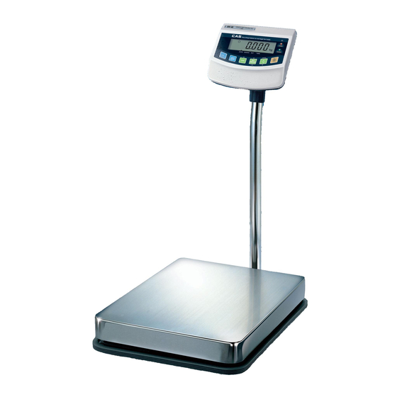
- Page 1 BATTERY WEIGHING SCALE BW-SERIES SERVICE MANUAL Revision : 2005. 5. 9 - 1 -...
-
Page 2: Table Of Contents
Table of Contents INTRODUCTION TECHNICAL SPECCIFICATION INSTALLATION & CONNECTION TEST MODE CALIBRATION MODE SET MODE SCHEMATIC DIAGRAM P.C.B DIAGRAM CONNECTION DIAGRAM PART LIST EXPLODED VIEW ERROR MESSAGE & TROUBLE SHOOTING - 2 -... -
Page 3: Introduction
INTRODUCTION The service manual is the specification for the BW-SERIES. They have been designed with CAS reliability under rigid quality control and with outstanding performance. This manual includes basic technical about composition of hardware and program function. TECHNICAL SPECIFICATION BW SERIES... -
Page 4: Installation & Connection
INSTALLATION & CONNECTION Installation - 4 -... -
Page 5: Test Mode
├─ ㅇ 8 Carrier Detect ├─ ㅇ 20 Data Terminal Ready └─ 9 pin port (Male) 25 pin port of PC (Female) RS-232C port of BW-SERIES RXD 1ㅇ ㅇ 3 Transmit Data --------------------------- TXD 2ㅇ ㅇ 2 Receive Data --------------------------- GND 5ㅇ... - Page 6 TEST 1 (Enter ‘TEST’ mode to start TEST 1.) FUNCTION : Liquid crystal display Test LC DISPLAY DESCRIPTION Display TEST 1 state. ENTER Key : Next menu TEST 2 FUNCTION : A/D conversion test LC DISPLAY DESCRIPTION ENTER Key : Next menu Display TEST 2 state.
-
Page 7: Calibration Mode
CALIBRATION MODE Moving method Open the top cover of indicator and power on with pressing CAL switch in the left top. At that time, LCD screen shows “ZEro=tESt tArE=CAL” message and pressing ‘TARE’ key moves to CAL 1. Calibration menu (CAL 1 ~ CAL 5) CAL 1 : Maximum Capacity Set CAL 2 : Minimum Division Set CAL 3 : Setting Weight in Span Calibration... - Page 8 CAL 3 FUNCTION : Setting Weight In Span Calibration LC DISPLAY DESCRIPTION Input by digit input method. CAL 3 condition ENTER : save and go to next menu 200 Kg ▶ Note 1. The span weight shall be within 10-100% of maximum capacity. The initial span weight is 100% of max.
-
Page 9: Set Mode
SET MODE Moving method If you press the * key for three seconds to normal operation state, after display “SET” message for one second and then enter F-1 menu. Available keys NET/GROSS Key : Increase the set point. TARE Key : Move to the next menu. ENTER Key : Return to the normal operation at completion of setting. -
Page 10: Schematic Diagram
SCHEMATIC DIAGRAM - 10 -... -
Page 11: P.c.b Diagram
P.C.B DIAGRAM MAIN PCB [ TOP SIDE ] [ BOTTOM SIDE ] - 11 -... - Page 12 DISPLAY PCB [ TOP SIDE ] [ BOTTOM SIDE ] - 12 -...
-
Page 13: Connection Diagram
CONNECTION DIAGRAM - 13 -... -
Page 14: Part List
PART LIST DISPLAY PCB ASS’Y ▶ BW-D/R TYPE CODE ITEM SPEC UNIT Q'TY REMARK 1050-A00-0468-0 HEAT SINK SY-468 SOCKET OF IC2 2090-H00-0011-0 LED HOLDER STD-110BLK(1mm) 6110-PBW-1040-C PCB-DISPLAY 6110-PBW-1040-C(BW/BI) 1998.11.20 6224-I00-7225-0 IC(DRIVER) UPD 7225G00 6241-I00-0317-0 IC(LINEAR) LM-317T 6515-CJ0-0022-0 RESISTOR 1/4W CFR 2.2Ω (±5%) 6515-CJ3-0051-0 RESISTOR 1/4W CFR 5.1K... - Page 15 MAIN PCB ASS’Y CODE ITEM SPEC UNIT Q'TY REMARK 6100-PBW-1040-D PCB-MAIN 6100-PBW-1040-D 1999.01.29 6200-IPU-1702-0 IC(CPU) ICS1702M(SOIC) 6200-IPU-9752-0 IC(CPU) GM97C52,GMS90C52(LG) 6205-I00-9346-0 IC(EEP ROM) S-93C46 6210-I00-8054-0 IC(RESET) S-80841ALY 6214-I00-7714-A AD-7714AN-5 6220-I00-2931-A IC(REGULATOR) LM2931AZ-5.0(SW TYPE) IC10 6240-I00-1081-0 IC(OP AMP) HIN232CP(ICL232CP,LT10 6240-I00-1100-0 LTC1100-CN8(BI,BW) 6241-I00-0330-0 IC(LINEAR) LM-330T 6241-I00-0393-0...
- Page 16 BATTERY SPRING B ø1*4*21(DL,EP) 1590-A00-0002-0 BATTERY SPRING C ø1*20*21(DL,EP) 1595-A00-0005-0 KNOB SPRING 1*3.5*3'/4(BW) 1595-A00-0015-A GROUND SPRING ø1*ø17*15(BW) SPEC PLATE PW-STICKER TYPE CAPACITY PLATE BW-SERIES 2005-A00-0014-B BODY 205*220*55(ABS)BI 2005-A00-0015-A FRONT COVER 205*220*32(ABS)BI 2005-A00-0021-0 DOOR KNOB 40*33*12(BI) 2014-A00-0002-0 BATTERY HOLDER 161*59*30(EP,BW) 2015-A00-0002-A DISPLAY COVER(ACRIL) BI-SERIES(153.6*60*2T)
- Page 17 POLY BAG 90*150*0.05T 3-8-7 9301-A00-0003-0 POLY BAG 170*250*0.05T(MANUAL) 3-8-6 9303-A00-0004-A POLY BAG 350*450*0.05T 9304-A00-0005-B POLY BAG 450*580*0.04T 9400-A00-0046-0 SILICAGEL 9900-A00-0001-0 SEALING SOLDER OVERSEA 3-8-4 9900-A00-0002-0 SEALING WIRE 300M/ROLL 0.002 3-8-5 MANUAL BW-SERIES 3-8-1 BATTERY C-SIZE 3-8-3 ADAPTOR 110/220V12V/850mA - 17 -...
- Page 18 POLY BAG 90*150*0.05T 3-8-7 9301-A00-0003-0 POLY BAG 170*250*0.05T(MANUAL) 3-8-6 9303-A00-0004-A POLY BAG 350*450*0.05T 9305-A00-0002-B POLY BAG 550*750*0.04T(SET,HD) 9400-A00-0046-0 SILICAGEL 9900-A00-0001-0 SEALING SOLDER OVERSEA 3-8-4 9900-A00-0002-0 SEALING WIRE 300M/ROLL 0.002 3-8-5 MANUAL BW-SERIES 3-8-1 BATTERY C-SIZE 3-8-3 ADAPTOR 110/220V12V/850mA - 18 -...
-
Page 19: Exploded View
EXPLODED VIEW HEAD ASS’Y - COMMON - 19 -... - Page 20 BODY ASS’Y – LOW CAPACITY CAPACITY SPACE (mm) 1.35 15kg 30kg - 20 -...
- Page 21 SET & C/T BOX ASS’Y – LOW CAPACITY - 21 -...
- Page 22 BODY ASS’Y – HIGH CAPACITY - 22 -...
-
Page 23: Error Message & Trouble Shooting
ERROR MESSAGE & TROUBLE SHOOTING Errors in weighing mode Err 01 ▶ Cause The indicator can’t be initialized due to platform shaking. ▶ Management Put the platform on a flat place without shaking and power on. Err 02 ▶ Cause The loadcell is connected wrongly or A/D conversion part has a fault. - Page 24 Errors in count mode Err 61 ▶ Cause The count unit weight and sample weight are set too high. ▶ Management Set the count unit weight low or the sample quantity high. Err 62 ▶ Cause The count unit weight and sample weight are set too low. ▶...


Need help?
Do you have a question about the BW-SERIES and is the answer not in the manual?
Questions and answers