
Related Manuals for CAS BI Series


Summary of Contents for CAS BI Series
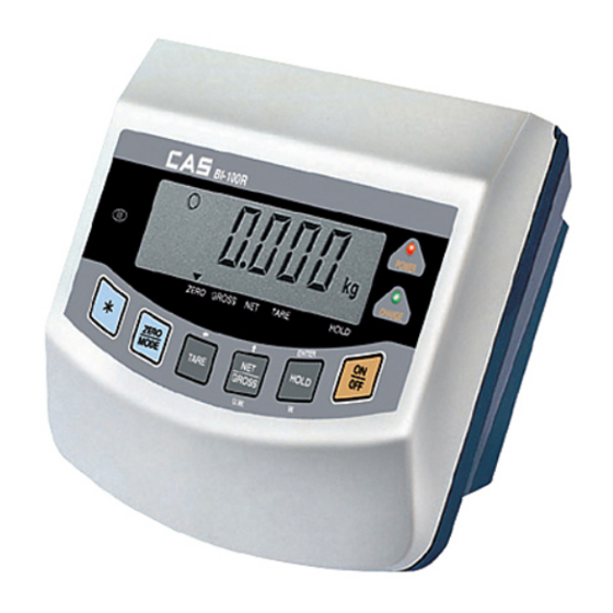
- Page 1 All manuals and user guides at all-guides.com BI Series Weighing Indicator OWNER’S MANUAL...
-
Page 2: Table Of Contents
All manuals and user guides at all-guides.com CONTENTS INTRODUCTION CAUTIONS FEATURES & MAIN FUNCTIONS SPECIFICATIONS PART NAME AND FUNCTION SYSTEM MODE GENERAL FUNCTION & DESCRIPTION CONVERSION MODE RS-232C COMMUNICATION INSTALLING USING & KEEPING BATTERY TEST FUNCTION CALIBRATION MODE SEALING & OPTIONAL DRAWING ERROR MESSAGE DESCRIPTION AND MANAGEMENT... -
Page 3: Introduction
All manuals and user guides at all-guides.com INTRODUCTION We greatly appreciate for you to purchase BI-SERIES of CAS. This goods has the excellent performance and splendid properties through strict test under severe quality management. It is recommended to read this manual in full before using BI-SERIES for good function application. -
Page 4: Specifications
All manuals and user guides at all-guides.com SPECIFICATION BI-SERIES MODEL ITEM BI-100D BI-100R BI-100DB BI-100RB DC1.2V(6EA) DC1.2V(6EA) DC1.5V(6EA) Recharging DC1.5V(6EA) Recharging Mn battery battery OPTIONAL Mn battery battery DC12V adapter DC12V adapter BACK LIGHT LOADCELL PERMISSION 5V DC VOLTAGE TEMPERATURE RANGE 10 C 40 C ZERO CALIBRATION RANGE... - Page 5 All manuals and user guides at all-guides.com Display part POWER CHARGE B A T ZERO GROSS NET TARE HOLD ZERO lamp : ON when the current weight is °∞0°± . TARE lamp : ON when the TARE weight is saved. GROSS weight lamp : ON at displaying the total weight.
-
Page 6: System Mode
All manuals and user guides at all-guides.com Key functions in Simple weighing mode & in Low/High comparing mode. KEY: Use to display NET weight or GROSS weight. GROSS KEY: Use to weigh the moving object. HOLD (Manual, Automatic) Key functions in COUNT mode KEY: Use to display the unit weight.(for approx. - Page 7 All manuals and user guides at all-guides.com KEY : Use to move the inputted value to the left by one place. KEY: Use to input a decimal point. ENTER KEY: Use to complete the input MODE Ex) For 20.5 input DISPLAY DESCRIPTION Press once...
- Page 8 All manuals and user guides at all-guides.com High/Low comparing mode conversion In case of no resetting the High/Low value DISPLAY PLATFORM DESCRIPTION Step 1 Press twice Press once Step 2 Empty ENTER Generally operated In case of resetting the High/Low value DISPLAY PLATFORM DESCRIPTION...
- Page 9 All manuals and user guides at all-guides.com COUNT MODE CONVERSION In case of no setting the unit/sample weight DISPLAY PLATFORM DESCRIPTION Step 1 Press three times Press once. Step 2 Empty ENTER Generally operated In case of setting the unit weight (Min.
- Page 10 All manuals and user guides at all-guides.com In case of setting the unit weight by sample (Samples : 10-200, 10 unit) DISPLAY PLATFORM DESCRIPTION Step 1 Press three times Step 2 Press once MODE Step 3 Press once Press once Step 4 MODE Press five times.
- Page 11 All manuals and user guides at all-guides.com COUNT COMPARING MODE CONVERSION In case of no setting the High/Low quantity DISPLAY PLATFORM DESCRIPTION Step 1 Press four times Press once. Step 2 ENTER Generally operated. In case of setting the High/Low quantity DISPLAY PLATFORM DESCRIPTION...
-
Page 12: General Function & Description
All manuals and user guides at all-guides.com GENERAL FUNCTION & DESCRIPTION REZERO FUNCTION(Use at change zero point) Rezero band range : Within 2% of Maximum capacity Zero point is changed Press Zero key. Zero lamp is ON. TARE FUNCTION(Use at weighing in use of TARE) Maximum TARE range : Maximum capacity Note : The weight including TARE weight can’t exceed the maximum capacity. - Page 13 All manuals and user guides at all-guides.com HOLD function (Use at weighing the moving object) Auto hold function(Hold function operated whenever weighing) Empty the platform. Press Hold key. Hold lamp is ON. Auto hold message is displayed for 1 sec. The weight is averaged for The hold weight is displayed When the weight change is...
-
Page 14: Conversion Mode
All manuals and user guides at all-guides.com CONVERSION MODE Enter method If you press the * key for three seconds to normal operation state, after display SET message for one second and then enter F-1 menu. Key using : Increase the set point. : Move to the next menu. - Page 15 All manuals and user guides at all-guides.com RXD 1 2 Transmit Data TXD 2 3 Receive Data GND 5 7 Signal Ground 4 Request To Send INDICATOR RS-232C port 5 Clear To Send 6 Data Set Ready 8 Carrier Detect 20 Data Terminal Ready Computer serial 25 pin port RXD 1...
- Page 16 All manuals and user guides at all-guides.com Data request mode If F-2 is set to 3, the indicator outputs the specified data when ASCII code corresponding to "D" is sent to it. *** Simple transmit/receive program(Language: BASIC) 10 OPEN "COM1: 9600, N, 8, 1" AS #1 20 IF LOC(1) = 0 THEN 60 30 A$ = INPUT$(1, 1) 40 PRINT A$;...
-
Page 17: Installing
All manuals and user guides at all-guides.com INSTALLING Loadcell connection Loadcell connector connect with the loadcell port of indicator back panel. Loadcell and connector connection Resolution to loadcell output rate. method 5V impression to loadcell Recommended Max. loadcell output resolution Load Cell Connector 2 mV... -
Page 18: Using & Keeping
All manuals and user guides at all-guides.com USING Replace the general(Mn, Alkaline)battery or charge the rechargeable battery in full at using after long-time storage. Open the top cover and check that the power switch in the left bottom is ON as follows. Power on by pressing ON/OFF key in the front panel. - Page 19 All manuals and user guides at all-guides.com Battery Rechargeable battery using and recharging Open the top cover and make as follows in the left bottom of cover at using the rechargeable battery. Open the jack protecting cap in the back panel and connect the adapter as follows.
-
Page 20: Test Function
All manuals and user guides at all-guides.com TEST FUNCTION Moving method Open the top cover of indicator and power on with pressing CAL switch in the left top. At that time, LCD screen shows “ZERO = TEST TARE = CAL” message and pressing ‘Zero’... - Page 21 All manuals and user guides at all-guides.com Key code Key name code Key name code ZERO TARE GROSS/NET HOLD TEST 4 Function : RS-232C communication test (Computer link test) Used key LCD screen Description Display TEST 4 state. ENTER key : Press once: Test running Press one more time: Receive : “1”...
-
Page 22: Calibration Mode
All manuals and user guides at all-guides.com Loadcell test method Power off before testing the loadcell output voltage and check that the loadcell output voltage(SIG+, SIG-) is same as the specified output voltage with ON/OFF key in the front panel pressed. CALIBRATION MODE Moving method Open the top cover of indicator and power on with CAL switch pressed. - Page 23 All manuals and user guides at all-guides.com CAL 1(Enter ‘Calibration’ mode to start CAl 1.) Function : Maximum Capacity setting Setting range from 1kg to 99999kg Used key LCD screen Description Input by digit input method. ENTER key : Move to 200kg the next menu.
- Page 24 All manuals and user guides at all-guides.com Reference 1. The span weight shall be within 10-100% of maximum capacity. The initial span weight is 100% of max. capacity but if the current span weight is different from it, input the desired weight again. Reference 2.
-
Page 25: Sealing & Optional Drawing
All manuals and user guides at all-guides.com SEALING Perform the sealing as shown in the below figure after the calibration is completed. Open the top cover. Cover CAL switch in the left top of cover with sealing plate and screw 2 sealing bolt. Connect the sealing wire as follows and compress the sealing lead. -
Page 26: Error Message Description And Management
Management Check that the printer connector has no fault. If the message is displayed in spite of no fault in printer and printer connector, call to A/S part of CAS CO., LTD. Err 09 Cause The current weight exceeds zero range. - Page 27 All manuals and user guides at all-guides.com Err 13 Cause The initial zero range exceeds above 10% of maximum capacity. Management Check the loadcell state. Over Cause Too heavy object is put on platform so that it may exceed the maximum capacity.
- Page 28 All manuals and user guides at all-guides.com Err 27 Cause Zero value is too low. Management Check that the platform is empty. Err 28 Cause The weight trembles. Management Check that the loadcell connector is properly connected. Errors in count mode Err 61 Cause The count unit weight and sample weight are set too high.
Need help?
Do you have a question about the BI Series and is the answer not in the manual?
Questions and answers