Table of Contents
Advertisement
ABOVE GROUND POOL & SPA HEATER
USERS & INSTALLATION MANUAL
READ AND FOLLOW ALL INSTRUCTIONS
FOR YOUR SAFETY - READ BEFORE OPERATING
Warning:
If you do not follow these instructions exactly, a fire or explosion may
result, causing property damage, personal injury or loss of life.
Warning: Improper installation, adjustment, alteration, service or maintenance can cause
property damage, personal injury or death. Installation and service must be performed by a
qualified installer, service agency or the gas supplier.
WHAT TO DO IF YOU SMELL GAS
•
For Your
•
•
Safety
•
PacFab, Inc.
Corporate Headquarters:
Western Operations:
Rev. A 2-4-2000
MiniMax 100
IMPORTANT SAFETY INSTRUCTIONS
SAVE THESE INSTRUCTIONS
WARNING
WARNING
Do not try to light any appliance.
Do not touch any electrical switch; do not use any phone in your building.
Immediately call your gas supplier from a neighbor's phone.
Follow the gas supplier's instructions.
If you cannot reach your gas supplier, call the fire department.
Do not store or use gasoline or other flammable vapors and liquids in
the vicinity of this or other appliances.
1620 Hawkins Ave., Sanford, NC 27330 • (919) 774-4151
10951 West Los Angeles Ave., Moorpark, CA 93021 • (805) 523-2400
(
Marked)
U.S. Patent Numbers
5,318,007 - 5,228,618
5,201,307 - 4,595,825
To
Consumer
Retain For
Future
Reference
P/N 471438
Advertisement
Table of Contents

Related Manuals for Pentair Pool Products PacFab MiniMax 100


Summary of Contents for Pentair Pool Products PacFab MiniMax 100
-
Page 1: Important Safety Instructions
MiniMax 100 Marked) ABOVE GROUND POOL & SPA HEATER USERS & INSTALLATION MANUAL IMPORTANT SAFETY INSTRUCTIONS READ AND FOLLOW ALL INSTRUCTIONS SAVE THESE INSTRUCTIONS WARNING FOR YOUR SAFETY - READ BEFORE OPERATING Warning: If you do not follow these instructions exactly, a fire or explosion may result, causing property damage, personal injury or loss of life. -
Page 2: Table Of Contents
TABLE OF CONTENTS: Introduction ............i Important Notices . -
Page 3: Introduction
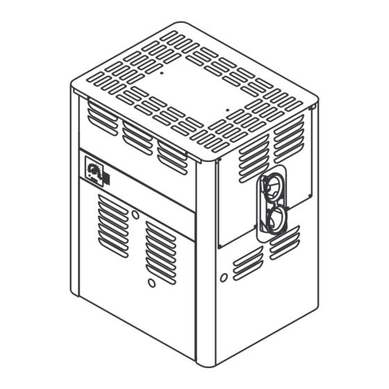
Introduction MiniMax 100 Marked) ABOVE GROUND POOL AND SPA HEATERS Congratulations on your purchase of a MiniMax 100 high performance heating system. Proper installation and service of your new heating system and correct chemical maintenance of the water will ensure years of enjoyment. The MiniMax 100 is a compact, lightweight and efficient gas fired high performance above ground pool and spa heater that can be connected to schedule 40 PVC pipe and has a built-in top. -
Page 4: Specifications
SPECIFICATIONS - TECHNICAL DATA (NATURAL GAS MODELS ONLY) CATEGORY GAS AND G20 @ 20mb. G20 @ 20mb. G20 @ 20mb. SUPPLY PRESSURE G25 @ 25mb. BURNER PRESSURE mbar 9.3 (3.7) (in.wg) (3.7) (3.7) 13.8 (5.5) HEAT INPUT GROSS 29.3 29.3 29.3 (Btu/h) (100,000) - Page 5 SPECIFICATIONS - TECHNICAL DATA (LPG MODELS ONLY) CATEGORY 3B/P GAS AND G31 @ 37mb. G31 @ 50mb. G30 @ 29mb. SUPPLY PRESSURE BURNER PRESSURE mbar 21.0 21.0 21.0 (in.wg) (8.4) (8.4) (8.4) HEAT INPUT GROSS 29.3 29.3 34.3 (Btu/h) (100,000) (100,000) (117,000) 26.96...
-
Page 6: Users Section
Users Section This instruction manual provides operating instructions, installation, and service information for the MiniMax 100 high performance heater. The information in this manual applies to the MiniMax 100 natural gas and L.P.G., DBI and millivolt standing pilot heater models. This heater is designed for the heating of fresh water swimming pools and spas, and should not be used for any other purpose. -
Page 7: Operating Instructions
Users Section MINIMAX 100 DIRECT-SPARK IGNITION LIGHTING/OPERATION- NATURAL GAS & PROPANE FOR YOUR SAFETY: READ BEFORE LIGHTING WARNING If you do not follow these instructions exactly, a fire or explosion may result causing property damage, personal injury or loss of life. A. - Page 8 Users Section MILLIVOLT LIGHTING/OPERATION- NATURAL GAS & PROPANE FOR YOUR SAFETY: READ BEFORE LIGHTING WARNING If you do not follow these instructions exactly, a fire or explosion may result causing property damage, personal injury or loss of life. BEFORE OPERATING: Smell all around the appliance area for gas. Be sure to smell next to the floor because some gas is heavier than air and will settle on the floor.
-
Page 9: Operating (Controls) / Heater Operation
Users Section OPERATING (CONTROLS) HEATER OPERATION DIRECT SPARK ELECTRONIC AND GENERAL MILLIVOLT MODELS The MiniMax 100 DBI employs a microprocessor based Direct Spark Ignition (DSI) system to light the For convenience and economy all MiniMax 100 main burner and therefore has no pilot. The ignition heaters are equipped with a thermostat on the front of circuit operates at 24 VAC and requires that a 230 the heater control panel;... - Page 10 Users Section Failure to Light- Lockout (DBI Models Only) Control Fault -Diagnostic LED Conditions 1. Should the main burner fail to light, or flame is not Error Mode LED Indication detected during the trial for ignition period the Internal Control Failure Steady on control will go into lockout and the valve will be turned off immediately.
-
Page 11: Maintenance Instructions
Users Section Maintenance MAINTENANCE INSTRUCTIONS SPRING AND AUTUMN OPERATION It is recommended that you check the following items at least every six months and at the beginning of every If the pool is being used occasionally, do not turn the swimming season. -
Page 12: Chemical Balance
Users Section CHEMICAL BALANCE If pH becomes too high (over alkaline), it has POOL AND SPA WATER these effects: Your MiniMax pool heater was designed specifically 1. Greatly lowers the ability of chlorine to destroy bacteria for your spa or pool and will give you many years of and algae. -
Page 13: Installation Section
Installation Section Installation Instructions SPECIFICATIONS IMPORTANT NOTICE: These installation instructions are designed for use by qualified personnel only, trained especially for installation of this type of heating equipment and related components. The heater must be installed on a level surface consisting entirely of, or a combination of, noncombustible materials such as steel, iron, brick, tile, concrete, slate, or plaster. -
Page 14: Outdoor Installation
Installation Section OUTDOOR INSTALLATION This heater is certified for outdoor installation. If the 6 in. heater is installed in very cold areas proper precautions are needed for freeze protection. The heater must be placed in a suitable area on a level, noncombustible surface. -
Page 15: Indoor Installation
Installation Section INDOOR INSTALLATION The installation of flueing systems should conform with When a heater is installed indoors, two air openings must be provided. One opening should be placed at the bottom the latest edition of BS 5440:1. and one at the top of the room to allow for a free flow of All products of combustion and flue gases must be air. -
Page 16: Flue Test
Installation Section FLUE TEST Use the following steps to perform a quick check of your flueing installation. Allow the heater to operate for 15 minutes. Close the doors in the room, then strike a wooden match and blow out the flame. Hold Fig. -
Page 17: Diagrams
Installation Section MiniMax 100 Electronic Direct Spark Ignition Wiring Diagram MiniMax CE100 ELECTRONIC WIRING DIAGRAM MODULE IF ORIGINAL FACTORY WIRING MUST BE REPLACED, INSTALLER MUST SUPPLY UL OR CSA (IF CANADA) APPROVED WIRE, 18 GAUGE, 600V, 150˚ C TEMPERATURE RATING. THERMAL FUSE WIRING MUST BE REPLACED WITH UL OR CSA (IF CANADA) APPROVED WIRE, 18 GAUGE, 600V, 150˚... -
Page 18: Plumbing Connections
Installation Section PLUMBING CONNECTIONS PRESSURE SWITCH The MiniMax 100 heater has the unique capability of The pressure switch will keep the circuit open when the direct schedule 40 or 80 CPVC/ABS/PVC plumbing connections. Either a Quick-Flange or Quick-Flange II pump is not on and operating. When the filter pump turns on, the pressure switch closes the circuit and the (depending on model ordered) has been included with the heater will operate. - Page 19 Installation Section PLUMBING CONNECTIONS THE GRAPHIC BELOW INDICATES THE PRESSURE DROP EXPECTED ACROSS THE APPLIANCE FOR ANY GIVEN FLOWRATE Rev. A 2-4-2000 P/N 471438...
-
Page 20: Water Connections
Installation Section WATER CONNECTIONS QUICK-FLANGE II INSTALLATION INSTRUCTIONS FOR 1½ SCHEDULE 40 CPVC or ABS PIPE or SCHEDULE 80 PVC (you may adapt to SCH 40 PVC 12 inches beyond the Quick Flange II) (1½ in. npt x 1½ in. CPVC/ABS slip Male Adaptor may be required) Figure 13. -
Page 21: Gas Connections
Installation Section GAS CONNECTIONS GAS LINE INSTALLATIONS Before installing the gas line, be sure to check which gas the heater has been designed to burn. This is important because different types of gas require different gas pipe sizes. The rating plate on the heater will indicate which gas the heater is designed to burn. -
Page 22: Commissioning
Installation Section / Commissioning COMMISSIONING FILLING THE SYSTEM 1. Ensure all power is off and all external controls are off. 2. Open all supply and return valves. 3. Fill heating system to minimum operating pressure. 4. Purge air from all system pipe work recharging the system to the minimum operating pressure. INITIAL FIRING Before commissioning the appliance, the whole gas installation, including the meter, MUST be pre-purged and tested for gas soundness in accordance with BS 6891:1988. - Page 23 Installation Section / Commissioning Upon completion of commissioning and testing the system, the installer should draw the user's attention to the following: 1. Give the "Users Instructions" to the householder and emphasise their responsibilities under the "Gas Safety (Installation and Use) Regulations 1994" (as amended). 2.
-
Page 24: Service Section
Servicing Section SERVICE SECTION Maintenance GENERAL To ensure safe and efficient operation of the appliance, it is recommended that the servicing is carried out at regular intervals, the frequency of which will vary depending on the condition of installation and usage: once every year will be adequate. -
Page 25: Soot Formation On The Heat Exchanger
Servicing Section SOOT FORMATION ON THE HEAT EXCHANGER Usual Causes of Sooting: 1. Low gas pressure in the gas supply line. 2. Excessive water flow can create condensation which can cause a soot formation. 3. Foreign material in burners and orifices. (Remove foreign material such as dirt, spider webs, etc.) 4. -
Page 26: Removing The Heat Exchanger
Servicing Section REMOVING THE HEAT EXCHANGER For heavy soot accumulation which cannot be successfully removed by merely brushing or use of a vacuum cleaner, the heat exchanger must be removed for the heater. 1. Isolate both gas and electrical supply to the heater. 2. -
Page 27: Troubleshooting - General
TROUBLESHOOTING - GENERAL Possible Cause Remedy Heater will not come on Automatic ignition system fails Check if electrical connections are correct and securely fastened – If YES, call serviceman. Pump not running Place pump in operation Pump air locked Check for leaks Filter dirty Clean filter Pump strainer clogged... -
Page 28: Exploded View & Parts List
EXPLODED VIEW P/N 471438 Rev. A 2-4-2000... -
Page 29: Parts List
PARTS LIST ITEM DESCRIPTION QUANT. PART NUMBER Indoor Draft Hood 471198 Outdoor Top 471213 Indoor Top (Cover) 471075 Indoor Stack Adaptor 471214 Metric Pipe Adaptor (not shown) 471490 Indoor Draft Hood Kit consisting of items 1, 2, 3 & 3A 471439 Middle Top 471069... - Page 30 NOTES P/N 471438 Rev. A 2-4-2000...
- Page 31 NOTES Rev. A 2-4-2000 P/N 471438...
- Page 32 PacFab, Inc. Corporate Headquarters: 1620 Hawkins Ave., Sanford, NC 27330 • (919) 774-4151 Western Operations: 10951 West Los Angeles Ave., Moorpark, CA 93021 • (805) 523-2400 P/N 471438 Rev. A 2-4-2000...
Need help?
Do you have a question about the PacFab MiniMax 100 and is the answer not in the manual?
Questions and answers