Table of Contents
Advertisement
Advertisement
Table of Contents

Subscribe to Our Youtube Channel
Related Manuals for Hertz HGS 2-15

Summary of Contents for Hertz HGS 2-15
- Page 1 HGS 2-15 OPERATOR HANDBOOK...
-
Page 3: Table Of Contents
TABLE OF CONTENTS: 1. CHAPTER SAFETY INTRODUCTION PERSONEL PROTECTIVE EQUIPMENTS PRESSURE LINE CONNECTIONS FIRE AND EXPLOSION RISK MOVING PARTS HOT AND SHARP SURFACES FLAMMABLE AND IRRITANT MATERIALS RISK OF ELECTRIC SHOCK LIFTING AND HANDLING 1.10 SUGGESTIONS 1.11 AIR RECEIVER 2. CHAPTER INSTALLATION, ASSEMBLY INSTALLATION AND CONNECTIONS COMPRESSOR ROOM VENTILATION... -
Page 5: Introduction
1. CHAPTER SAFETY 1.1 INTRODUCTION Pay attention to all the safety and operation regulations mentioned in this handbook, this way the accident probability will be minimized and the life of machine will increase. Do not make any modification on the machine without taking the approval of Manufacturer. Prior the assembly, starting and maintenance of the machine ensure that the handbook is carefully read by related personnel (operators, maintenance personnel etc). -
Page 6: Moving Parts
Maintain the electrical and pressure connections in good condition. Immediately replace the damaged cables or hoses. Maintain these connections clean and regularly. Ensure that there is not any loose or broken electrical cable at any point of the compressor. Remove this cable in case of risk of electricity. Prior to welding remove sound insulation materials. -
Page 7: Risk Of Electric Shock
1.8 RISK OF ELECTRIC SHOCK Along with the information and recommendations in this handbook; your compressor should be installed in conformity to all related national and international standards. The electrical wiring works must be performed by a qualified electrician. Ensure that sufficient grounding is made and the grounding cable is connected to portion marked with on the compressor body. -
Page 8: Suggestions
1.10 SUGGESTIONS After repair, maintenance and adjustment works make sure that there is not any spare part, cleaning material or hand tool are left inside. Make sure that all the guards are installed after repair, maintenance or adjustment works. Make sure that none of the moving parts are in contact with any component. Do not leave unplugged electric conducting cables. -
Page 9: Installation, Assembly
2. CHAPTER INSTALLATION & ASSEMBLY 2.1 INSTALLATION OF THE COMPRESSOR AND CONNECTIONS The floor on which the compressor is mounted should be capable of carrying the weight of compressor and should be flat and dry. There is no need to fixing (anchorage bolt etc) to the floor. -
Page 10: Compressor Layout (Belt Driven)
POWER CABLE SPECIFICATIONS (3x380V-400V AC) CABLE CROSS SECTION MAIN FUSE MODEL POWER (HP/KW) (mm²) CURRENT (A) HGS 2 3 / 2,2 4 x 2,5 mm (Maksimum 25m) 10 A HGS 3 4 / 3 4 x 2,5 mm (Maksimum 25m) 10 A HGS 4 5,5 / 4... -
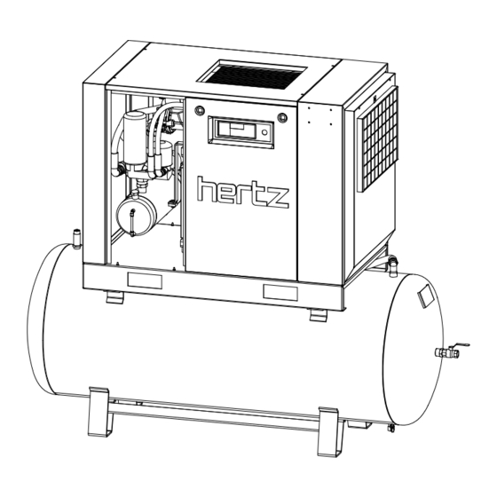
Page 11: Compressor Layout (Direct Drive)
COOLER INTAKE FILTER COMPRESSOR UNIT MOTOR OIL RECEIVER OIL DISCHARGE VALVE NOTE: DEPENDING ON THE MODEL COOLER MAY BE ON THE TOP OR SIDE. THE ABOVE FIGURE WAS USED FOR GENERAL VIEW. 2.5 COMPRESSOR LAYOUT (DIRECT DRIVE MODELS) - Page 12 COOLER SEPERATOR PRESSURE SWITCH CONTROLLER UNIT OIL FILTER COMPRESSOR UNIT MOTOR Note: For easy follow electric box was not shown on the figure.
-
Page 13: Technical Data
3. CHAPTER TECHNICAL DATA 3.1 TECHNICAL DATA COMPRESSOR TYPE/SERIAL NO MAXIMUN WORKING PRESSURE MINIMUM WORKING PRESSURE CAPACITY m³/min WORKING VOLTAGE WORKING FREQUENCY AMBIENT TEMPERATURE Between 2 C° / 40 º C AVERAGE WORKING TEMPERATURE Between 75 / 96 °C AIR EXIT TEMPERATURE COOLER FAN FLOW m³/hour NOISE LEVEL... -
Page 14: Dimensions
TYPE DRUCK SERIENNUMMER PRESSURE SERIAL NO m /dak HERSTELLUNGSDATUM KAPAZITÄT CAPACITY m /min MANUF. DATE COMPRESSOR LEISTUNG NENNSPANNUNG PLATE V3Ph NOM.POWER VOLTAGE NENNSTROM FREQUENZ CURRENT FREQUENCY ELEKTRISCHER GEWICHT SCHALTPLAN WEIGHT ELEC.DIAG. NO Max.Pressure PS Act. Thick Vessel Maximaler Druck Wandstärke/Druckbehälter HYD.Test Pressure Ph Corrosion All Hydrostaticher Testdruck... -
Page 15: Operation
4. CHAPTER OPERATION 4.1 GENERAL In order to enable you to easily see the operation and adjustment values of the compressor, an electronic controller unit is installed to the system. The electrical and mechanical precautions have been taken for establishing of operational safety. Some of the equipments of the compressor are described below for your information. -
Page 16: Operation Of The Compressor
4.3 OPERATION OF THE COMPRESSOR The electric motor of compressor (1) rotates airend unit (2). Airend unit absorbs the air passing from pilot intake section of the intake valve (3) and sends it to separator tank (5) after mixing with oil. This way pressure inside separator tank (internal pressure) starts to rise. -
Page 17: Start Up (Commisioning)
4.4 START-UP Before start up the compressor, check the electrical and air line connections. Check that the compressor’s cooling air inlets and outlets are not closed. Do not cover your compressor with cloth, nylon etc. Do not operate if covered. Inside electrical panel of your compressor there is a “phase control relay”... -
Page 18: Daily Operation
By looking at the screw pulley of the compressor; press “Start “ button and run the compressor for a short while (1-2 seconds) and stop it by pressing emergency stop button. When looked from fan side, it should rotate in counter clockwise direction. (That is indicated by an arrow) If the rotation direction is correct, restart it after 1 minute. -
Page 19: Maintenance
5. CHAPTER MAINTENANCE 5.1 GENERAL SINCE YOUR COMPRESSOR IS A COMPLICATED MACHINE; MAINTENANCE ACTIVITIES PERFORMED BY UNAUTHORIZED AND NON TRAINED PERSONNEL WILL ABOLISH ALL GUARANTEE AND MAY CAUSE UNDESIRED DAMAGE AND INJURIES. While the compressor is running never remove any cover or part. Prior the maintenance;... -
Page 20: Maintenance Instructions
5.4 MAINTENANCE INSTRUCTIONS COMPRESSOR FLUID o In our compressors HERTZ KOMPRESSOREN SMARTOIL 2000 type of oil is being used. This oil is specially produced by taking into account of compressor operation type as you will se below. o As the chemical structures and contributions of different types of oils are different; mixing them with each other or using them in the compressor may cause a severe damage with a high cost. -
Page 21: Oil And Oil Filter Replacement
OIL AND OIL FILTER REPLACEMENT Replace the oil and oil filter at every 2000 hours. If within 6 months 2000 hours is not completed, replace it once every 6 months. In case of oil change definitely replace the oil filter. - BELT DRIVEN MODELS OIL CHARGING PLUG OIL FILTER... -
Page 22: Panel Filter Replacement
PANEL FILTER REPLACEMENT Panel filter keeps the dust trying to go inside the compressor. Filter change depends on the ambient conditions and maintenance but should be changed every 2000 hours or 6 months To change the panel filter; After switching off the compressor remove the screws connecting the top perforate to suction cowling. -
Page 23: Separator Element Replacement
SEPARATOR ELEMENT REPLACEMENT - BELT DRIVEN MODELS - DIRECT DRIVEN MODELS SEPARATOR ELEMENT Change the separator element every year. If compressor runs more than 4000 hours change the separator every 4000 hours To change the separator element; Stop the compressor. Evacuate all internal pressure Remove the separator element with filter key Oil the gasket of new separator element... -
Page 24: Cooler Maintenance
Do not expand the diameter of the scavenge orifice, otherwise the capacity of your compressor reduces. THE MAINTENANCE OF COOLER For keeping the cooler clean, you should not hinder the cleaning of the panel filter. As the cooling air passes between the cells of the cooler, small amount of dust goes between the cooler cells and this start to block the cells. -
Page 25: Troubleshooting
6. CHAPTER TROUBLESHOOTING 6.1 INTRODUCTION The information in this section is based on the experience gained by the service activities and tests conducted at factory. The indications and reasons of failures are ordered according to the results obtained from the warnings of our company and the experience of the service personnel. - Page 26 AFTER DE-ENERGIZING THE COMPRESSOR CHECK WHETHER THE BELTS ARE FREELY ROTATING. IF THE ROTATION IS MORE DIFFICULT THAN NORMAL, THERE MAY BE MECHANICAL DAMAGE AT MOTOR OR AT COMPRESSOR UNIT; INFORM THE SERVICE. COMPRESSOR DOES NOT PRODUCE AIR. (DOES NOT GET LOADED) 1- THE COMPRESSOR DOES NOT TRANSFER FROM STAR TO DELTA.
- Page 27 MAIN MOTOR OVERLOAD RELAY STOPS THE COMPRESSOR 1- OVERLOAD RELAY ADJUSTMENT IS CHANGED OBSERVE THAT THE RELAY IS ADJUSTED ACCORDING TO THE MOTOR TEMPLATE. OBSERVE THAT (ON FULL LOAD) THE MOTOR CURRENT IS NORMAL AND STABLE (THE CURRENT DIFFERENCE BETWEEN THE PHASES SHOULD BE LESS THAN 10 %) IF THE RELAY OPENS BEFORE THE ADJUSTED VALUE IT IS DEFECTED.
- Page 28 THE COMPRESSOR OPERATES HOTTER THEN NORMAL 1- OIL LEVEL IS LOW CHECK THE OIL LEVEL AND FILL IF NECESARRY 2- THE AMBIENT TEMPERATURE IS HIGH CHECK THE AMBIENT TEMPERATURE 3- VENTILATION IS INSUFICIENT THE HOT AIR OUTLET CAN NOT BE DISCHARGED OUT OF COMPRESSOR ROOM HEALTHILY. THE COOLER MAY BE DIRECTLY SUBJECT TO SUN LIGHT AND THERE MAY BE STRONG WIND OPPOSITE TO THE HOT AIR OUTLET.
-
Page 29: L8-Control Panel
7. CHAPTER L8 - CONTROL PANEL INFO SCREEN START RESET STOP BUTTONS : START : RUNS COMPRESSOR. STOP : STOPS COMPRESSOR. RESET : SHOWS WORKING TEMPERATURE, WORKING HOURS, RESETS ALARMS, VERIFY THE MODIFICATIONS OF SET VALUES. LED (X10), (X100) : MULTIPLICATIVE FACTOR LED. WORKING DESCRIPTION : 1- WHEN COMPRESSOR CONNECTED THE POWER SUPPLY. - Page 30 USING THIS MANUAL WHEN YOU SEE DISPLAY ADVANCE VIA BUTTONS ON THE RIGHT. screen USING THIS MANUAL : WHEN YOU SEE DISPLAY ADVANCE VIA BUTTONS ON THE RIGHT. PRESS SIMULTANEOUSLY TO THE FRAMED BUTTONS. FIRST PRESS LEFT-HAND SIDE BUTTON SIMULTANEOUSLY PRESS THE OTHER ONE.
- Page 31 PARAMETERS CODE DESCRIPTION SET VALUE PRESSURE CONTROL * ( 0 = TRANSDUCER, 1 = PRESURE SWITCH ) TOP RANGE PRESSURE TRANSDUCER 15 Bar HIGH PRESSURE ALARM 8,8 – 11 – 14,3 Bar STOP PRESSURE 7,5 – 10 – 13 Bar START PRESSURE 6,5 –...
- Page 32 ALARM CODES CODE DESCRIPTION SETTING DATA LOST, (LOADING FACTORY DEFAULTS) PHASE FAULT MAIN MOTOR OVERLOADED (RESET OVERLOAD SWITCH IN ELECTRIC BOX) HIGH WORKING TEMPERATURE (SCREW TEMP. HIGHER THAN FOREWARNING HIGH TEMPERATURE (SCREW TEMP. HIGHER THAN WITH AUTOMATICALLY RESET AS SOON AS THE TEMPERATURE DECREASES -2°C TEMPERATURE SENSOR IS DEFECTIVE LOW TEMPERATURE (TEMPERATURE LOWER THAN...
Need help?
Do you have a question about the HGS 2-15 and is the answer not in the manual?
Questions and answers