
Subscribe to Our Youtube Channel
Related Manuals for Viola Systems arctic c-1220


Summary of Contents for Viola Systems arctic c-1220
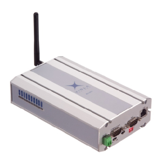
- Page 1 Arctic C-Series User Manual Arctic Communication Gateway (C-1220, C-1230, C-1240, C-1260) Firmware Version 3.1.5 Document Version 1.0 May 2015...
-
Page 2: Copyright And Trademark
Arctic Communication Gateway Copyright and Trademark Copyright © 2008-2015, Viola Systems Ltd. All rights to this manual are owned solely by Viola Systems Ltd. (referred elsewhere in this User’s Manual as Viola Systems). All rights reserved. No part of this manual may be transmitted or reproduced in any form or by any means without a prior written permission from Viola Systems. -
Page 3: Disclaimer
The names of the programs as well as all copyrights relating to the programs are the sole property of Viola Systems. Any transfer, licensing to a third party, leasing, renting, transportation, copying, editing, translating, modifying into another programming language or reverse engineering for any intent is forbidden without the written consent of Viola Systems. -
Page 4: Declaration Of Conformity
User's Manual Arctic Communication Gateway Declaration of Conformity (according to ISO/IEC Guide 22 and EN 45014) Manufacturer’s Name: Viola Systems Ltd. Manufacturer’s Address: Lemminkäisenkatu 14-18 B FI-20520 Turku Finland declares that this product: Product Name: Arctic Communication Gateway conforms to the following standards: EMC: IEC 61850-3 (Edition 2.0 2013-12) -
Page 5: Warranty And Safety Instructions
Viola Systems manufactured hardware or software could lead directly to death, personal injury, or severe physical or environmental damage. -
Page 6: Revisions
User's Manual Arctic Communication Gateway Revisions Date Document version Firmware version Description of changes 05/2015 Manual released Firmware Version 3.1.5 Document Version 1.0... -
Page 7: Table Of Contents
User's Manual Arctic Communication Gateway Contents COPYRIGHT AND TRADEMARK ..................2 DISCLAIMER..........................3 DECLARATION OF CONFORMITY..................4 WARRANTY AND SAFETY INSTRUCTIONS...............5 REVISIONS..........................6 1. INTRODUCTION....................... 9 About this User’s Manual......................9 Arctic C-series – Communication Gateways.................9 2. PHYSICAL INTERFACES....................10 Front Panel Description.......................10 Back Panel Description....................... - Page 8 User's Manual Arctic Communication Gateway 6. ADDITIONAL SYSTEM CONFIGURATION..............30 Changing system password....................30 Date and time........................30 System log...........................31 Factory default settings....................... 31 Firmware update........................31 Configuration profiles......................31 7. TROUBLESHOOTING.....................33 SPECIFICATIONS ......................34 LIMITED WARRANTY......................36 TECHNICAL SUPPORT ..................... 37 Firmware Version 3.1.5 Document Version 1.0...
-
Page 9: Introduction
User's Manual Arctic Communication Gateway 1 Introduction 1.1 About this User’s Manual This User’s Manual describes the operation of the Arctic Communication Gateway. All devices in this User’s Manual are referred to as Arctic, unless otherwise mentioned. This manual provides introductory information as well as detailed instructions on how to set up and manage the Arctic as part of a network environment. -
Page 10: Physical Interfaces
User's Manual Arctic Communication Gateway 2 Physical Interfaces The Arctic unit contains three panels for interface connections and status indication. 2.1 Front Panel Description The front panel of the Arctic consists of the following connectors and switches: Figure 2. Front Panel Description 1. - Page 11 User's Manual Arctic Communication Gateway Figure 3. Power supply connector ■ Pin 1 is positive (+) ■ Pin 2 is negative (–) The unit is protected against reversed polarity in specified voltage range. Power Switch Enables or disables the operation of the Arctic. Console Enable Switch Enables or disables console access.
- Page 12 User's Manual Arctic Communication Gateway Figure 4. DB9 male connector The serial port 1 (RS1) is a full RS-232 port. The pin description of this port is as follows: Table 2: RS-232 Port PIN Description Pin Number Name Direction Explanation Data Carrier Detect Received Data Transmitted Data...
-
Page 13: Back Panel Description
User's Manual Arctic Communication Gateway The figure and pin description of the Arctic’s RJ45 Ethernet connector is as follows: Figure 5. RJ45 Ethernet connector Table 4: RJ45 Ethernet connector PIN Description Pin Number Name Direction Explanation Data Receive Positive Rx– Data Receive Negative Data Transmit Positive Tx–... -
Page 14: Side Panel Description
User's Manual Arctic Communication Gateway 1. SMA (female) connector for an antenna. 2. SIM Card slot. 2.3 Side Panel Description The side panel of the device contains ten LEDs which are used to indicate the status of the Arctic and only five of them are connected. The LEDs are numbered from 1 to 10 starting from the rear panel side. -
Page 15: Product Information Label
User's Manual Arctic Communication Gateway State Description Number LED 1 Not connected LED 2 Not connected LED 3 Not connected LED 4/GPRS Blinking Wireless communication is starting or transferring data Wireless communication is inactive 2.4 Product Information Label The product information label on the underside of the Arctic contains the following information: 1. -
Page 16: Quick Installation
User's Manual Arctic Communication Gateway 3 Quick Installation 3.1 Connection Principle The Arctic has configurable network interfaces, Ethernet WAN or Ethernet LAN port for a cable network, and Mobile WAN for wireless communication. The WAN interfaces are used for connecting the Arctic to public Internet or private APN. - Page 17 User's Manual Arctic Communication Gateway 1. Configure the computer to use the same IP address space as the Arctic (laptop IP for example 10.10.10.11 with netmask 255.0.0.0). Check with ping command. 2. Connect to the Arctic using the web browser. The default IP address of Arctic is 10.10.10.10 (netmask 255.0.0.0).
-
Page 18: Setting Ethernet Port Function To Lan
User's Manual Arctic Communication Gateway 3. Enter the username and password and press Login button in the log-in screen. The actual screen depends on the used web browser. Note! Default username is viola-adm and default password is violam2m. It is recommended that the default password is changed before the product is connected to a public network. -
Page 19: Configuring Mobile Wan (Cellular Network Interface)
User's Manual Arctic Communication Gateway Note! Make the following change before changing any other Ethernet settings. 1. In the left pane, select Network > Ethernet Port . 2. Change Port function to LAN. 3.5 Configuring Mobile WAN (cellular network interface) The Mobile WAN interface is used for connecting the Arctic to a cellular network. - Page 20 User's Manual Arctic Communication Gateway 5. If both Ethernet WAN and Mobile WAN configured, define the Backup WAN Interface. If the primary WAN interface comes down, the Arctic automatically switches default route to backup WAN interface. The figure below shows example configuration where Ethernet WAN is configured as default route.
-
Page 21: Network Configuration
User's Manual Arctic Communication Gateway 4 Network Configuration This chapter describes how to configure network interfaces. 4.1 Configuration screens 4.1.1 Host and domain names Host and domain names can be set from the System General Settings screen. Figure 12. General Settings 4.1.2 Ethernet WAN This screen configures the Ethernet WAN interface on Arctic . -
Page 22: Mobile Wan
User's Manual Arctic Communication Gateway to be configured towards the correct backup gateway. Backup Gateway parameter is not needed if WAN redundancy is implemented with wireless connection. See section WAN Failover and backup routing settings on page 23 for more details about WAN redundancy. 4.1.3 Mobile WAN This screen configures the Mobile WAN interface on the Arctic. -
Page 23: Wan Failover And Backup Routing Settings
User's Manual Arctic Communication Gateway servers are used for resolving names to IP addresses. Figure 14. Mobile WAN configuration To configure the mobile WAN, enable the connection by selecting "Enable"="Yes" on the top of the page and enter PIN code if set, APN name and authentication details if needed. -
Page 24: Ethernet Lan
User's Manual Arctic Communication Gateway Figure 15. WAN Failover configuration To enable any default routes, set "WAN Default Route"="Yes". Any route settings are not effective if this parameter is not enabled. Set "On Demand"="Yes" if the backup WAN interface to come up only when primary interface goes down. -
Page 25: Routing
User's Manual Arctic Communication Gateway Figure 17. Network monitor configuration The usage of the monitor is heavily recommended to detect the connection drops. 4.2 Routing 4.2.1 Routing parameters There are multiple configuration options that define the routing on Arctic : ■... -
Page 26: Default Route
User's Manual Arctic Communication Gateway ■ WAN Failover - Secondary Backup WAN Interface (selection: None/Mobile WAN/Ethernet WAN/Ethernet WAN Secondary) ■ These three settings configure the high level default gateways. Must be configured to enable default route. ■ OpenVPN Client Settings - Interface (selection: Any WAN/Ethernet WAN/ Wireless WAN/Ethernet LAN) ■... -
Page 27: Mobile Wan Status Leds
User's Manual Arctic Communication Gateway Figure 18. Network status screen 4.4.2 Mobile WAN status LEDs Table 5: LED Description on page 14. 1. COM LED starts to blink when the connection is started. 2. SIM LED starts to blink when SIM card is searched and turns on when the card is found and PIN code accepted. - Page 28 User's Manual Arctic Communication Gateway Figure 19. Modem info screen Firmware Version 3.1.5 Document Version 1.0...
-
Page 29: Serial Port Configuration
User's Manual Arctic Communication Gateway 5 Serial Port Configuration 5.1 Configuring a serial port The Arctic supports the following serial port application modes: Application Mode Description Serial device protocol Serial Gateway Transparent connection to any serial device IEC-104 IEC-101 to IEC-104 IEC-101 conversion Modbus... -
Page 30: Additional System Configuration
User's Manual Arctic Communication Gateway 6 Additional System Configuration 6.1 Changing system password Username and password can be changed from Tools > User Config screen. It is always recommended to change the password from the factory default when the Arctic is connected to a public network. Figure 21. -
Page 31: System Log
User's Manual Arctic Communication Gateway 6.3 System log System log is visible on the Tools > System Log screen. To refresh the system log, use web browser reload button. 6.4 Factory default settings To restore factory default settings, go to Tools > Default settings . 6.5 Firmware update Create a backup of the current configuration starting the firmware update. - Page 32 User's Manual Arctic Communication Gateway Figure 25. Configuration profiles Firmware Version 3.1.5 Document Version 1.0...
-
Page 33: Troubleshooting
User's Manual Arctic Communication Gateway 7 Troubleshooting Q: Wireless WAN is not coming up A: Check settings (Mobile WAN on page 22), SIM card and signal level. Q: OpenVPN is not working A: For more information, see OpenVPN application note. Send a request to support@violasystems.com for the note. -
Page 34: Specifications
User's Manual Arctic Communication Gateway Specifications Table 6: Technical specifications Processor 32 bit RISC Memory (RAM) 128MB Hard Drive (flash) 128MB Input voltage (nominal) 12-48VDC Power consumption 7W max Power connector Phoenix Contact 2-pin Casing Aluminium sheet Operating temperature -30 - 70 °C Storage temperature -40 ... - Page 35 User's Manual Arctic Communication Gateway Antenna connector type is SMA (female). SIM card type is 2FF (Mini SIM). Table 8: Application serial port specifications Serial mode (RS1) RS-232 Serial mode (RS2) RS-232 / 422 / 485 adjustable Baud rate 300 - 460800 Data bit 5 / 6 / 7 / 8 Parity...
-
Page 36: Limited Warranty
Viola Systems’ sole option and expense, and Viola Systems may use a new or refurbished parts or products to do so. If Viola Systems is unable to repair or replace a defective product, an alternate exclusive remedy shall be a refund of the original purchase price. -
Page 37: Technical Support
User's Manual Arctic Communication Gateway Technical Support Contacting Technical Support Phone: +358 20 1226 226 Fax: +358 20 1226 220 E-mail: support@violasystems.com Internet: http://www.violasystems.com Recording Arctic Information Before contacting our Technical Support staff, please record (if possible) the following information about the Arctic product: Product name: ___________________________________________________ Serial no:...
Need help?
Do you have a question about the arctic c-1220 and is the answer not in the manual?
Questions and answers