
Related Manuals for Digitus DN-170041


Summary of Contents for Digitus DN-170041
-
Page 1: User Manual
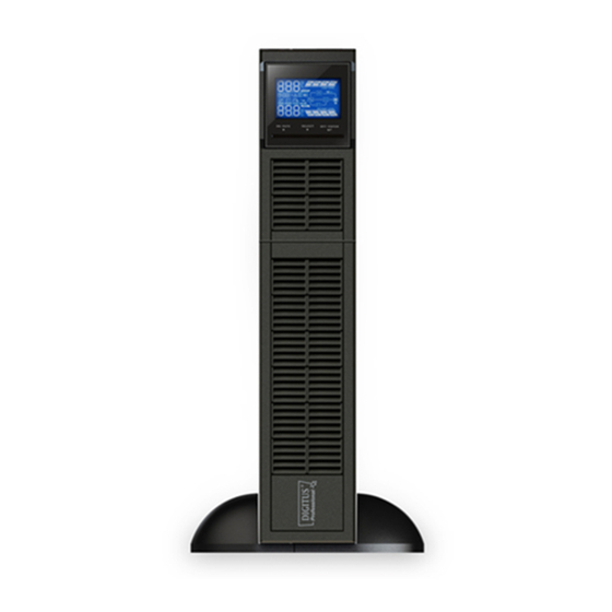
USER MANUAL DN-170040/ DN-170041 Online UPS Uninterruptible Power Supply System Version:1.0... -
Page 2: Table Of Contents
Table of Contents 1. Important Safety Warning ..............1 1-1. Transportation ................1 1-2. Preparation ..................1 1-3. Installation ..................1 1-4. Operation ..................1 1-5. Maintenance, service and faults ............2 2. Installation and setup ................3 2-1 Rear panel view ................3 2-2. -
Page 3: Important Safety Warning
1. Important Safety Warning Please comply with all warnings and operating instructions in this manual strictly. Save this manual properly and read carefully the following instructions before installing the unit. Do not operate this unit before reading through all safety information and operating instructions carefully 1-1. -
Page 4: Maintenance, Service And Faults
1-5. Maintenance, service and faults The UPS system operates with hazardous voltages. Repairs may be carried out only by qualified maintenance personnel. Caution - risk of electric shock. Even after the unit is disconnected from the mains (building wiring outlet), components inside the UPS system are still connected to the battery and electrically live and dangerous. -
Page 5: Installation And Setup
Model No. Type Model No. Type DN-170040 DN-170040L Standard Long-run DN-170041 DN-170041L 2-1 Rear panel view 1K/1.5K IEC 2K IEC 3K IEC 1. Programmable outlets: connect to non-critical loads. 2. Output receptacles: connect to mission-critical loads. 3. AC input 4. -
Page 6: Install The Ups
2-2. Install the UPS For safety consideration, the UPS is shipped out from factory without connecting battery wires. Before install the UPS, please follow below steps to re-connect battery wires first. Step 1 Step 2 Step 3 Remove front panel. Connect the AC input and Put the front panel back to the re-connect battery wires. -
Page 7: Communication Port
Step 2: UPS output connection For socket-type outputs, there two kinds of outputs: programmable outlets and general outlets. Please connect non-critical devices to the programmable outlets and critical devices to the general outlets. During power failure, you may extend the backup time to critical devices by setting shorter backup time for non-critical devices. -
Page 8: Battery Replacement
Step 7: Install software For optimal computer system protection, install UPS monitoring software to fully configure UPS shutdown. Please follow steps below to download and install monitoring software: 1. Go to the website http://www.power-software-download.com 2. Click ViewPower software icon and then choose your required OS to download the software. 3. -
Page 9: Battery Kit Assembly (Option)
Step 7 Put the front panel back to the unit. 2-5 Battery Kit Assembly (option) NOTICE: Please assemble battery kit first before installing it inside of UPS. Please select correct battery kit procedure below to assemble it. 2-battery kit Step 1: Remove adhesive tapes. Step 2: Connect all battery terminals by following below chart. - Page 10 Step 3: Put assembled battery packs on Step 4: Cover the other side of plastic shell as one side of plastic shells and insert one below chart. Then, battery kit is assembly well. more defect battery on the space. Dummy battery 4-battery kit Step 1: Remove adhesive tapes.
- Page 11 6-battery kit Step 1: Remove adhesive tapes. Step 2: Connect all battery terminals by following below chart. Tapes Tapes Step 3: Put assembled battery packs on Step 4: Cover the other side of plastic shell as one side of plastic shells. below chart.
-
Page 12: Operations
3. Operations 3-1. Button operation Button View Button Function Turn on the UPS: Press and hold ON/Mute button for at least 2 seconds to turn on the UPS. Mute the alarm: After the UPS is turned on in battery mode, press and hold this button for at least 5 seconds to disable or enable the alarm system. -
Page 13: Lcd Panel
3-2. LCD Panel Display Function Remaining backup time information Indicates the remaining backup time in pie chart. Indicates the remaining backup time in numbers. H: hours, M: minute, S: second Fault information Indicates that the warning and fault occurs. Indicates the warning and fault codes, and the codes are listed in details in 3-5 section. -
Page 14: Audible Alarm
Indicates the Battery level by 0-25%, 26-50%, 51-75%, and 76-100%. Indicates the battery is fault. Indicates low battery level and low battery voltage. Input & Battery voltage information Indicates the input voltage or frequency or battery voltage. Vac: Input voltage, Vdc: battery voltage, Hz: input frequency 3-3. -
Page 15: Ups Setting
3-5. UPS Setting There are three parameters to set up the UPS. Parameter 1: It’s for program alternatives. Refer to below table. Parameter 2 and parameter 3 are the setting options or values for each program. 01: Output voltage setting ... - Page 16 04: ECO enable/disable Interface Setting ENA: ECO mode enable DIS: ECO mode disable(Default) 05: AECO enable/disable Interface Setting ENA: Advanced ECO mode enable DIS: Advanced ECO mode disable(Default) 06: Bypass mode enable/disable when UPS is off Interface Setting ENA: Bypass mode is enabled when UPS is off DIS: Bypass mode is disabled when UPS is off (Default)
- Page 17 09: Acceptable input voltage range setting Interface Setting For 200/208/220/230/240 VAC models, you may choose the following selection for acceptable input voltage range: 110/300 flashing in turns: The acceptable input voltage range is from 110V to 300V. 160/260 flashing in turns: The acceptable input voltage range is from 160V to 260V.
-
Page 18: Operating Mode Description
3-6. Operating Mode Description Operating Description LCD display mode Online mode When the input voltage is within acceptable range, UPS will provide pure and stable AC power to output. The UPS will also charge the battery at online mode. ECO mode When the input voltage is within setting (Efficiency range (±3%Vo max), UPS will bypass... -
Page 19: Faults Reference Code
Standby mode UPS is powered off without output power, but the battery still can be charged. Fault mode The UPS is in fault mode when no output power is supplied from the UPS and the fault icon flashes on the LCD display, although the information of UPS can be displayed in the screen. -
Page 20: Troubleshooting
4. Troubleshooting If the UPS system does not operate correctly, please solve the problem by using the table below. Symptom Possible cause Remedy No indication and alarm even The AC input power is not Check if input power cord though the main is normal. connected well. - Page 21 Symptom Possible cause Remedy Fault code is shown as 43 and The The UPS shut down Remove excess loads from automatically because of UPS output and restart it. icon is lighting on LCD overload at the UPS display and alarm is continuously output.
-
Page 22: Storage And Maintenance
5. Storage and Maintenance 5-1. Operation The UPS system contains no user-serviceable parts. If the battery service life (3~5 years at 25°C ambient temperature) has been exceeded, the batteries must be replaced. In this case, please contact your dealer. Be sure to deliver the spent battery to a recycling facility or ship it to your dealer in the replacement battery packing material. -
Page 23: Specifications
6. Specifications DN-170040 DN-170041 MODEL Capacity VA/W 1500 VA / 1350 W 3000 VA / 2700 W INPUT Low Line 80 VAC/70 VAC/60 VAC/55 VAC ± 5 % or 160 VAC/140 VAC/120 VAC/110 VAC ± 5 % Transfer (based on load percentage 100%-80% / 80%-70% / 70%-60% / 60%-0) Low Line 85 VAC/75 VAC/65 VAC/60 VAC ±...
Need help?
Do you have a question about the DN-170041 and is the answer not in the manual?
Questions and answers