Jacobsen 67978 Parts & Maintenance Manual
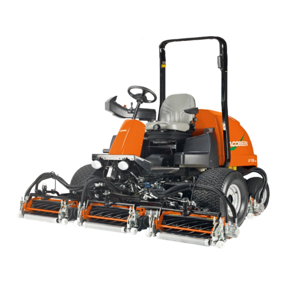
Lightweight fairway mower with rops
Hide thumbs
Also See for 67978:
- Safety & operation manual (62 pages) ,
- Maintenance manual (167 pages) ,
- Operation manual (30 pages)
Table of Contents
Advertisement
Quick Links
Parts & Maintenance Manual
Manual de piezas y mantenimiento
Lightweight Fairway Mower with ROPS
Cortacésped ligero para calle de campo de golf con
protección antivuelco (ROPS)
67978 – LF 550
67979 – LF 550
67981 – LF 570
67982 – LF 570
67980 – LF 550
67983 – LF 570
WARNING: If incorrectly used this machine can cause severe
injury. Those who use and maintain this machine should be
trained in its proper use, warned of its dangers and should
read the entire manual before attempting to set up, operate,
adjust or service the machine.
ADVERTENCIA: Si se usa de forma incorrecta, esta máquina
puede causar graves lesiones. Cualquier persona que use y
mantenga esta máquina deberá estar entrenada en su uso
correcto, instruida de sus peligros y deberá leer el manual
completamente antes de tratar de instalar, operar, ajustar o
revisar la máquina.
GB
ES
United
Spain
Kingdom
™
, Kubota V1505-E3B, 5 Gang 2WD
™
, Kubota V1505-E3B, 5 Gang 4WD
™
, Kubota V1505-E3B, 5 Gang 2WD
™
, Kubota V1505-E3B, 5 Gang 4WD
™
Turbo, Kubota V1505-T-E3B, 5 Gang 4WD
™
Turbo, Kubota V1505-T-E3B, 5 Gang 4WD
WARNING
ADVERTENCIA
4229041-ES-Rev A
When Performance Matters.
™
Advertisement
Chapters
Table of Contents

Related Manuals for Jacobsen 67978


Summary of Contents for Jacobsen 67978
- Page 1 Manual de piezas y mantenimiento Lightweight Fairway Mower with ROPS Cortacésped ligero para calle de campo de golf con protección antivuelco (ROPS) ™ 67978 – LF 550 , Kubota V1505-E3B, 5 Gang 2WD ™ 67979 – LF 550 , Kubota V1505-E3B, 5 Gang 4WD ™...
-
Page 2: Service Parts
Jacobsen Dealer. Suggested Stocking Guide To Keep your Equipment fully operational and productive, Jacobsen suggests you maintain a stock of the more commonly used maintenance items. We have included part numbers for additional support materials and training aids. To order any of the following material: 3. -
Page 3: Table Of Contents
Table of Contents 1 Safety 5 Maintenance Operating Safety ..........4 General ............22 Important Safety Notes ........5 Engine ............22 2 Specifications Engine Oil ............ 22 Product Identification ........6 Air filter ............23 V1505-E3B Engine ........6 Fuel ............. 23 V1505-T-E3B Engine ........6 Fuel System .......... -
Page 4: Safety
Only use accessories and attachments 21. To prevent tipping or loss of control, do not start or stop approved by Jacobsen. suddenly on slopes. Reduce speed when making sharp turns. Use caution when changing directions. -
Page 5: Important Safety Notes
Adjustments and maintenance should always be performed by a qualified technician. If additional information or service is needed, contact your Authorized Jacobsen Dealer who is kept informed of the latest methods to service this equipment and can provide prompt and efficient service. -
Page 6: Specifications
SPECIFICATIONS SPECIFICATIONS PRODUCT IDENTIFICATION_________________________________________________ 67978 ......LF 550, 2WD with ROPS, uses 5 in. (127 mm) diameter reel 11524 WILMAR BLVD, ® 67979 ......LF 550, 4WD with ROPS, uses 5 in. CHARLOTTE, NC 28273 A Textron Company 1-800-848-1636 (US) PRODUCT OF U.S.A. -
Page 7: Mower
(kg) Weights (Mower with reels): Lbs. (kg) 67978 Overall (less operator)...... 2837 (1287) 67981 Overall (less operator) ..... 3135 (1422) 67979 Overall (less operator ....... 2960 (1343) 67982 Overall (less operator) ..... 3274 (1485) 67980 Overall (less operator)...... 2974 (1349) 67983 Overall (less operator) ..... -
Page 8: Declaration Of Conformity
Producentens firmanavn og fulde adresse Bedrijfsnaam en volledig adres van de fabrikant Tootja ärinimi ja täielik aadress Valmistajan toiminimi ja täydellinen osoite Nom commercial et adresse complète du fabricant Firmenname und vollständige Adresse des Herstellers Jacobsen, A Textron Company A gyártó üzleti neve és teljes címe Ragione sociale e indirizzo completo del fabbricante 11524 Wilmar Blvd. - Page 9 Místo a datum prohlášení Sted og dato for erklæringen Plaats en datum van de verklaring Deklaratsiooni väljastamise koht ja kuupäev Vakuutuksen paikka ja päivämäärä Lieu et date de la déclaration Jacobsen, A Textron Company Ort und Datum der Erklärung A nyilatkozat kelte (hely és id ) Luogo e data della dichiarazione 11524 Wilmar Blvd.
-
Page 10: Accessories
SPECIFICATIONS ACCESSORIES ___________________________________________________________ Refer to the Parts Catalog and contact your area Jacobsen Dealer for a complete listing of accessories and attachments. CAUTION Use of other than Jacobsen authorized parts and accessories may cause personal injury or damage to the equipment. -
Page 11: Ldu
Diesel engine coolant is under pressure. Turn engine off and allow fluid to cool before checking fluid level or adding coolant to radiator. JACOBSEN VERSION X.XX Parking Brake Light: Red parking brake light located on right side of the LDU indicates the parking brake switch is engaged. -
Page 12: Alarm Codes
When ignition switch is turned to the RUN position, the tank is low. Visually inspect mower for obvious signs Jacobsen start-up screen is displayed for five seconds. of leaks around connections, hoses, and hydraulic The start-up screen displays controller software revision components. - Page 13 3.1.5 Maintenance Mode Mow Speed: To set the maximum mow speed, press forward or backward on the joystick (H) until the set max Maintenance Mode is used by the superintendent to set mow speed screen is on the LCD display. Press the black and adjust functional values for the mower.
- Page 14 Traction ENGINE TEMP Configuration. 120F Press and hold ENTER PIN? black button. 1234 Enter PIN. Calibrate traction CALIBRATE PEDAL? pedal. Calibrate forward PEDAL FORWARD pedal movement. CRUISE CRUISE Cruise Control ENABLED DISABLED Setting. Calibrate reverse PEDAL REVERSE pedal movement. Traction TRACTION TRACTION Change Max...
-
Page 15: Adjustments
ADJUSTMENTS ADJUSTMENTS GENERAL ________________________________________________________________ adjustment cannot be made, contact an authorized Jacobsen Dealer. WARNING Replace, do not adjust, worn or damaged components. To prevent injury, lower implements to the ground, Do not wear jewelry or loose fitting clothing when disengage all drives, engage parking brake, stop engine, making adjustments or repairs. -
Page 16: Bedknife Adjustment
ADJUSTMENTS BEDKNIFE ADJUSTMENT __________________________________________________ Read Section 4.2 before making the adjustment. Note: Avoid excessive tightening or damage may occur to bedknife and reel blades. Reels must turn freely. CAUTION To prevent personal injury and damage to the cutting edges, handle the reel with extreme care. Start adjustment at leading end of reel, followed by the trailing end. -
Page 17: Flash Attach
ADJUSTMENTS ™ FLASH ATTACH __________________________________________________________ Installing Cutting units Carefully raise arm until cutting unit can be removed. Place each cutting unit in front of its respective lift arm. Raise lift arm and position cutting unit so that yoke (T) is in line with swivel housing (S). -
Page 18: Belt
ADJUSTMENTS BELT ____________________________________________________________________ Inspect and adjust new belt after first ten hours of operation. Adjust every 100 hours thereafter. Adjust alternator pulley so belt deflects 1/4 to 5/16 in. (6 to 8 mm) with a 20 lb. push at midpoint between pulleys. See engine manual. -
Page 19: Steering Toe-In
ADJUSTMENTS STEERING TOE-IN _________________________________________________________ Turn wheels to straight ahead position. Loosen jam nuts (J) on both sides of tie rod (M). Turn tie rod (M) to provide proper toe-in. Toe-in must not exceed +1/16 in. (1.5 mm) (K). Retighten jam nuts. After adjusting tie rod, adjust steering cylinder by threading the rod (N) in or out of ball joint so spindle arm (L) clears the stop on the axle by 1/32 to 3/32 in. -
Page 20: Armrest Pivot
ADJUSTMENTS 4.11 ARMREST PIVOT__________________________________________________________ 1. Tighten or loosen pivot plunger (W) as required so plunger button stops the armrest at both ends of armrest pivot slots, and plunger body does not contact armrest pivot. Do not use plunger to increase pivot tension. -
Page 21: Torque Specification
All torque values included in these charts are approximate and are for reference only. Use of these torque values is at your sole risk. Jacobsen is not responsible for any loss, claim, or damage arising from the use of these charts. -
Page 22: Maintenance
If the injection pump, injectors, or the fuel system require engine. service, contact an authorized Jacobsen Dealer. During the break-in period, Jacobsen recommends the NOTICE following: The mower is designed to operate and cut most During the first 50 hours of operation, a new engine efficiently at the preset governor setting. -
Page 23: Air Filter
MAINTENANCE AIR FILTER _______________________________________________________________ Check the service indicator daily. If red band appears in the Reassemble cap making sure it seals completely window (B) replace the element. around the filter housing. Dust evacuator must be facing down. Do not remove the element for inspection or cleaning. Check all hoses and air ducts. -
Page 24: Battery
MAINTENANCE BATTERY ________________________________________________________________ Make absolutely certain the ignition switch is OFF and the Verify battery polarity before connecting or disconnecting the battery cables. key has been removed before servicing the battery. When installing the battery, always assemble the RED, positive (+) battery cable first, and the ground, BLACK, CAUTION negative (-) cable last. -
Page 25: Muffler And Exhaust
5.12 HYDRAULIC OIL___________________________________________________________ Refer to Section 7.2 for specific maintenance intervals. After oil has drained install drain plug and fill with Jacobsen Hydraulic oil. Drain and replace the hydraulic oil after a major component Purge air from system. failure, or if you notice the presence of water or foam in the oil, or a rancid odor (indicating excessive heat). -
Page 26: Hydraulic Filters
Check the interlock system, fuses, and circuit breakers regularly. If the interlock does not function properly and the problem cannot be corrected, contact an authorized Jacobsen Dealer. Keep the wire harness and all individual wires away CIRCUIT BREAKER from moving parts to prevent damage. -
Page 27: Radiator
If you have to add coolant more than once a month, or add more than one quart at a time, have a Jacobsen Drain and refill annually. Remove the radiator cap, open the Dealer check the cooling system. -
Page 28: Wheel Mounting Procedure
Repair damaged metal surfaces and use Jacobsen NOTICE touch-up paint. Wax the equipment for maximum paint protection. Do not wash any portion of the equipment while it is hot. -
Page 29: Reel Backlapping
MAINTENANCE 5.20 REEL BACKLAPPING ______________________________________________________ WARNING To prevent severe injury, keep hands, feet, and clothing away from rotating reels. Carbon monoxide in the exhaust fumes can be fatal when inhaled. Never operate the engine without proper ventilation. Check the reel and bedknife to determine if backlapping or grinding will restore the cutting edge. -
Page 30: Storage
MAINTENANCE 5.21 STORAGE ________________________________________________________________ General Cutting Units Wash the mower thoroughly and lubricate. Repair and Wash the cutting units thoroughly, then repair and paint paint damaged or exposed metal. any damaged or exposed metal. Inspect the mower, tighten all hardware, and replace Lubricate all fittings and friction points. -
Page 31: Troubleshooting
TROUBLESHOOTING TROUBLESHOOTING GENERAL ________________________________________________________________ The troubleshooting chart below lists basic problems that may occur during start-up and operation. For more detailed information regarding the hydraulic and electrical systems contact your area Jacobsen Dealer. Symptoms Possible Causes Action Engine will not start. -
Page 32: Maintenance & Lubrication Charts
*** Inspect visible hoses and tubes for leaks or oil marks. Pack bearings with NLGI Grade 2 (Service Class GB) Manual grease gun with NLGI Grade 2 (Service Class LB). III Engine Oil - See Section 5.3 IV Jacobsen Hydraulic Oil - SAE 10W30 or Greens Care 68 en-32... -
Page 33: Lubrication Chart
MAINTENANCE & LUBRICATION CHARTS LUBRICATION CHART______________________________________________________ 11 13 Grease points same for all reels Grease Fittings F1 - 50 Hours (Every Week) Swivel Housing Lift Arm Lift Cylinders Lift Arm Pivot Brake Pedal Pivot Traction Pedal Pivot Ball Joint Steering Pivot Steering Cylinder 10 Axle Pivot F2 - 100 Hours... -
Page 34: Parts Catalog
Screw, 1/4-20 x 2” Hex Head HOW TO ORDER PARTS____________________________________________________ Write your full name and complete address on the Send or bring the order to an authorized Jacobsen Dealer. order. Inspect all shipments on receipt. If any parts are Explain where and how to make shipment. - Page 35 PARTS CATALOG TABLE OF CONTENTS______________________________________________________ 1.1 ..Decals..............36 2.1 ..Hood ............... 38 3.1 ..Seat Pan ..............40 4.1 ..Armrest Support ............ 42 5.1 ..Armrest..............44 6.1 ..Traction Pedal............46 7.1 ..Frame and Front Axle..........48 8.1 ..ROPS ..............50 9.1 ..2WD Steering ............52 10.1 ..4WD Steering ............
- Page 36 Jacobsen. Guía de inventario sugerido Para mantener el equipo perfectamente operativo y productivo, Jacobsen recomienda mantener un inventario de las piezas de mantenimiento usadas con más normalidad. Hemos incluido los números de piezas de materiales de apoyo y ayudas para formación adicionales.
- Page 37 Índice SEGURIDAD MANTENIMIENTO Manipulación segura .......... 4 Generalidades ..........22 Notas importantes sobre seguridad ....5 Motor ..............22 Aceite de motor ..........22 ESPECIFICACIONES Filtro de aire ............. 23 Identificación del producto ........6 Combustible ............. 23 Motor V1505-E3B ..........6 Sistema de combustible ........
-
Page 38: Seguridad Manipulación Segura
Utilice accesorios acoplamientos aprobados por Jacobsen. 21. Para evitar un vuelco o pérdida de control, no arranque ni pare repentinamente en pendientes. Reduzca la velocidad Sea consciente de los posibles agujeros en el terreno y al realizar giros. Tenga cuidado al cambiar de dirección. -
Page 39: Notas Importantes Sobre Seguridad
Los ajustes y operaciones de mantenimiento siempre deberán ser realizadas por un técnico cualificado. Si necesita más información, póngase en contacto con su distribuidor Jacobsen, quien le informará de los métodos de mantenimiento más recientes y le proporcionará un servicio puntual y eficaz. -
Page 40: Especificaciones
ESPECIFICACIONES ESPECIFICACIONES IDENTIFICACIÓN DEL PRODUCTO___________________________________________ 67978 ......LF 550, 2WD con ROPS, molinete de 5" (127 mm) de diámetro ® 11524 WILMAR BLVD, CHARLOTTE, NC 28273 67979 ......LF 550, 4WD con ROPS, molinete A Textron Company 1-800-848-1636 (US) PRODUCT OF U.S.A. -
Page 41: Cortacésped
Anchura - Transporte ............ 2209 Pesos (cortacésped con molinetes): Pesos (cortacésped con molinetes): 67981 Total (menos operario) ........1422 67978 Total (menos operario) ........1287 67982 Total (menos operario) ........1485 67979 Total (menos operario) ........1343 67983 Total (menos operario) ........1490 67980 Total (menos operario) ........ -
Page 42: Declaración De Conformidad
Producentens firmanavn og fulde adresse Bedrijfsnaam en volledig adres van de fabrikant Tootja ärinimi ja täielik aadress Valmistajan toiminimi ja täydellinen osoite Nom commercial et adresse complète du fabricant Firmenname und vollständige Adresse des Herstellers Jacobsen, A Textron Company A gyártó üzleti neve és teljes címe Ragione sociale e indirizzo completo del fabbricante 11524 Wilmar Blvd. - Page 43 Místo a datum prohlášení Sted og dato for erklæringen Plaats en datum van de verklaring Deklaratsiooni väljastamise koht ja kuupäev Vakuutuksen paikka ja päivämäärä Lieu et date de la déclaration Jacobsen, A Textron Company Ort und Datum der Erklärung A nyilatkozat kelte (hely és id ) Luogo e data della dichiarazione 11524 Wilmar Blvd.
-
Page 44: Accesorios
ESPECIFICACIONES ACCESORIOS ____________________________________________________________ Consultar el Catálogo de Piezas y ponerse en contacto con su distribuidor Jacobsen para recibir una lista completa de accesorios y herramientas . PRECAUCIÓN El uso de componentes diferentes de las piezas y accesorios autorizados Jacobsen puede ocasionar lesiones personales o daños en los equipos e invalidará... -
Page 45: Ldu
El refrigerante del motor diesel está a presión. Apague el motor y deje que se enfríe el líquido antes de revisar el nivel o añadir refrigerante al radiador. JACOBSEN VERSION X.XX Luz de freno de estacionamiento: La luz roja de freno de estacionamiento situada en... - Page 46 RUN (funcionamiento), se muestra la pantalla de eleva hasta la posición de subida completa y la luz de puesta en marcha de Jacobsen durante cinco segundos. La nivel de aceite se enciende cuando el nivel del fluido pantalla de puesta en marcha muestra los niveles de hidráulico del depósito está...
- Page 47 3.1.5 Modo de mantenimiento ___________ Velocidad de corte: Para ajustar la velocidad máxima de sesgado, pulse hacia delante o hacia atrás en el joystick (H) hasta que aparezca la pantalla de velocidad máxima de El Modo de mantenimiento es utilizado por el encargado sesgado en la pantalla LCD.
- Page 48 Configuración ENGINE TEMP de tracción. 120F Mantenga pulsado ENTER PIN? el btón negro. 1234 Escriba el PIN. Calibrar el pedal CALIBRATE PEDAL? de tracción. Calibrar el movimiento PEDAL FORWARD del pedal hacia delante. CRUISE CRUISE Ajuste de ENABLED DISABLED control de Calibrar el movimiento crucero.
-
Page 49: Ajustes Generalidades
Si no ADVERTENCIA se puede realizar el ajuste deseado, póngase en con- tacto con un distribuidor Jacobsen autorizado. Al objeto de evitar posibles lesiones, baje al suelo el grupo de herramientas de corte, desactive todas las... -
Page 50: Ajuste De La Cuchilla Fija
AJUSTES AJUSTE DE LA CUCHILLA FIJA _____________________________________________ Lea la Sección 4.2 antes de realizar ningún ajuste. Cuando el molinete esté ajustado correctamente a la cuchilla fija, el molinete girará libremente y se podrá cortar un trozo de papel, por toda la longitud del molinete con el papel a 90°... -
Page 51: Flash Attach
AJUSTES FLASH ATTACH ___________________________________________________________ Instalación de las unidades de corte Con cuidado levantar el brazo hasta que se pueda quitar la unidad de corte. Colocar la unidad de corte frente a su respectivo brazo de elevación. Levantar el brazo de elevación y poner la unidad de corte para que el yugo (T) esté... -
Page 52: Correa
AJUSTES CORREA_________________________________________________________________ Revisar y ajustar la correa al cabo de las primeras diez horas de operación. Después ajustar cada 100 horas. Ajustar la polea del alternador para que la correa tenga una holgura de 6 - 8 mm, con 10 kg apretar en el centro entre las poleas. -
Page 53: Convergencia De La Dirección
AJUSTES CONVERGENCIA DE LA DIRECCIÓN__________________________________________ Poner las ruedas en dirección hacia delante. Aflojar las contratuercas (J) a ambos lados en el tirante (M). Girar el tirante (M) para que se pueda remolcar correctamente. El remolque no debe exceder 1,5 mm (K). -
Page 54: Pivote Del Reposabrazos
AJUSTES 4.11 PIVOTE DEL REPOSABRAZOS ______________________________________________ 1. Apriete o afloje el émbolo (W) lo necesario para que el pomo del émbolo detenga el reposabrazos en los dos extremos de las ranuras de pivote y que el cuerpo émbolo toque pivote reposabrazos. -
Page 55: Especificaciones Del Par De Torsión
Tenga siempre especial cuidado al utilizar valores de par de torsión. Jacobsen utiliza pernos metalizados Grado 5 de serie, a menos que se cite lo contrario. Para tensar pernos metalizados, utilice el valor dado para los lubricados. -
Page 56: Mantenimiento
Si fuera necesario poner en servicio la bomba de inyección, vida útil. los inyectores o el sistema de combustible, póngase en contacto con un distribuidor Jacobsen autorizado. Durante el período de rodaje, Jacobsen recomienda lo siguiente : AVISO Durante las primeras 50 horas de funcionamiento, se debe dejar que el nuevo motor alcance una tempera- El cortacésped ha sido diseñado para funcionar y cortar... -
Page 57: Filtro De Aire
MANTENIMIENTO FILTRO DE AIRE __________________________________________________________ Compruebe el indicador de mantenimiento diariamente. Si Vuelva a montar el tapón asegurándose de que se en la ventana (B) aparece la banda roja reemplace el filtro. asiente completamente alrededor del alojamiento del filtro. El evacuador de polvo debe mirar hacia abajo. No extraiga el filtro para inspeccionarlo o limpiarlo. -
Page 58: Batería
MANTENIMIENTO BATERÍA_________________________________________________________________ Esté absolutamente seguro de que el interruptor de Verifique la polaridad de la batería antes de conectar o desconectar los cables. encendido esté apagado y que se haya retirado la llave de contacto antes de poner en servicio la batería. Cuando instale la batería, monte siempre el cable posi- tivo (+) ROJO en primer lugar y el cable negativo (-) PRECAUCIÓN... -
Page 59: Escape Y Silenciador
Después de drenar el aceite, instale el inserto de mantenimiento. drenaje y llene el depósito con aceite hidráulico Jacobsen. Drene y reemplace el aceite hidráulico si ha tenido lugar un Purgue el aire del sistema. fallo de componentes grave, si advierte la presencia de agua... -
Page 60: Filtros Hidráulicos
Si el sistema no funciona correctamente y no se puede corregir el problema, póngase en contacto con un distribuidor Jacobsen autorizado. Aleje el mazo de cables y todos los cables individuales de las piezas móviles para evitar daños. -
Page 61: Radiador
Distribuidor de radiador. Vaciar y limpiar la botella de recuperación. Jacobsen deberá revisar el sistema refrigerante. 5.16 ESTRUCTURA DE PROTECCIÓN ANTIVUELCO (ROPS) __________________________ Disponemos de un sistema de protección antivuelco 1. -
Page 62: Montaje De Las Ruedas
AVISO Repare las superficies metálicas dañadas y utilice pintura para retoques Jacobsen. Aplique una capa de cera al No lave nada del equipo si está caliente. No utilice equipo para proteger la pintura. -
Page 63: Esmerilado Del Molinete
MANTENIMIENTO 5.20 ESMERILADO DEL MOLINETE _______________________________________________ Importante: Las válvulas de control de velocidad limitan la velocidad en marcha atrás solamente. Una vez ADVERTENCIA ajustada la velocidad de esmerilado, las válvulas se pueden quedar en esta posición para el corte normal. Si es Para evitar lesiones graves, mantener las manos, pies y necesaria la velocidad total en marcha atrás, por ejemplo ropa alejados de los molinetes en movimiento. -
Page 64: Almacenamiento
MANTENIMIENTO 5.21 ALMACENAMIENTO _______________________________________________________ Generalidades PRECAUCIÓN Lave el cortacésped a fondo y lubríquelo. Repare y pinte el metal dañado o desnudo. Para evitar que se produzcan lesiones y daños en los bordes de corte, manipule el molinete con sumo Inspeccione cortacésped, apriete todos... -
Page 65: Resolución De Problemas
En el siguiente cuadro se enumeran los problemas más comunes que pueden ocurrir durante el arranque y funcionamiento. Para más información detallada acerca de los sistemas hidráulico y eléctrico, póngase en contacto con el distribuidor Jacobsen de su zona . Síntomas Posibles Causas Acción... -
Page 66: Cuadros De Mantenimientoy Lubricación
*** Revisar manguitos y tubos visibles sobre fugas o marcas de aceite. ** O cada dos años, lo que suceda primero. IV Aceite hidráulico Jacobsen - SAE 10W30 o Greens Care 68 .I Cojinetes NLGI Grado 2 (Clase Servicio LB) II Pistola engrase manual NLGI Grado 2 (Clase Servicio LB) III Aceite de motor - ver Sección 4.3... -
Page 67: Cuadro De Lubricación
CUADROS DE MANTENIMIENTO Y LUBRICACIÓN CUADRO DE LUBRICACIÓN _________________________________________________ 11 13 Puntos de engrase igual para todos los molinetes Accesorios de engrase F1 - 50 horas (Cada Semana) Bastidor Giratorio Brazo Elevación Cilindros Elevación Pivote Brazo Elevación Pivote Pedal Freno Pivote Pedal Tracción Unión Bola Pivote Dirección... -
Page 68: Catálogo De Piezas
1. Escriba su nombre y dirección completos en el 5. Envíe o lleve el pedido a un distribuidor autorizado pedido. Jacobsen. 2. Indique la dirección y el método de envío: 6. Revise todos los envíos al recibirlos. Si alguna pieza está... - Page 69 CATÁLOGO DE PIEZAS es-35...
-
Page 70: Decals
LF 550 Serial No. All 1.1 Decals ® 4181865 Manufactured under one or more of the following U.S. patents: XXXXXX XXXXXX XXXXXX XXXXXX A Textron Company 4199140 838363 LF 550 LF 550 LF 550 4WD TURBO LF 570 LF 570 LF 570 4WD TURBO... - Page 71 3008930 Decal, Flash Attach 3008683 Decal, Backlap Located on Front Axle 4181862 Decal, Radiator Cap Warning Located on top of Radiator 4182386 Decal, Jacobsen Emblem 4181865 Decal, Instruction 3008521 Decal, Traction Pedal 4187681 Decal, Jacobsen 4181864 Decal, Battery Warning Located on Controller Housing...
-
Page 72: Hood
LF 550 Serial No. All 2.1 Hood 17 22 LF34-1... - Page 73 LF 570 Item Part No. Qty. Description Serial Numbers/Notes 4210824 Hood Assembly Includes Items 8 on Illustration 1.1 4218040 • Foam, Front 4218042 • Foam, Right Side 4218043 • Foam, Left Side 4218041 • Foam, Top 4130360 • Seal, Trim 5 Foot Length, Cut to Size 4221520 •...
-
Page 74: Seat Pan
LF 550 Serial No. All 3.1 Seat Pan Harita Seat... - Page 75 LF 570 Item Part No. Qty. Description Serial Numbers/Notes 1004279 Floor Pan 4218500 Seat Pan 4217621 Support, Seat 4210561 Adjuster, Double Latching 4222229 Plug, 2 x 2” Tube 400258 Screw, 3/8-16 x 3/4” Hex Head 441602 Carriage Bolt, 5/16-18 x 3/4” 445795 Nut, 5/16-18 Spiralock Flange 446142...
-
Page 76: Armrest Support
LF 550 Serial No. All 4.1 Armrest Support... - Page 77 LF 570 Item Part No. Qty. Description Serial Numbers/Notes Armrest Assembly 4188380 Support, Upper Armrest 4189843 Screw, M6-1 x 65 mm Hex Head 4188484 Flange, M6 Body Fastener 473211 Spacer, Black Neoprene 4209240 Pivot, Lower Armrest Support 450193 Screw, M8-1.25 x 20 mm Hex Head 450411 Lockwasher, M8 4188569...
-
Page 78: Armrest
LF 550 Serial No. All 5.1 Armrest Switches R Reel Light Accessory Horn Outlet C Reel L Reel Horn Joystick... - Page 79 LF 570 Item Part No. Qty. Description Serial Numbers/Notes 4233480 Armrest, Upper 4168560 Armrest, Lower 4189540 Screw, M4-0.7 x 20 mm Torx 4188480 Flange, M4 x 4 mm Body 4188482 Spacer, Black Neoprene 4219300 Harness, LDU 843942 • Socket, 12V Accessory Plug •...
-
Page 80: Traction Pedal
LF 550 Serial No. All 6.1 Traction Pedal... - Page 81 LF 570 Item Part No. Qty. Description Serial Numbers/Notes 4218260 Pedal, Traction REFERENCE U3, See 47.1 4235560 Plate, Pedal Support 400128 Screw, 1/4-20 x 3-1/2” Hex Head 453023 Flat Washer, 1/4 4233220 Spacer 446130 Lockwasher, 1/4 Heavy 3003474 Grip, Pedal 4230160 Mount, Arm 450399...
-
Page 82: Frame And Front Axle
LF 550 Serial No. All 7.1 Frame and Front Axle 12 15... - Page 83 LF 570 Item Part No. Qty. Description Serial Numbers/Notes 1 4236060 Tire, 26.5 x 14-12 4 Ply 4210442 Rim, 12 x 10.5 360111 Valve, Inflation 4209440 Wheel Motor See 42.1 4222844 • Seal Kit 4222842 • Shaft, Module 4222843 • Brake Module 4222840 •...
-
Page 84: Rops
LF 550 Serial No. All 8.1 ROPS... - Page 85 LF 570 Item Part No. Qty. Description Serial Numbers/Notes 4218320 ROPS 5000465 Screw, 1/2-13 x 1-1/4” Hex GR 8 446154 Lockwasher, 1/2 Heavy 4193182 Seat Belt Kit 400370 Screw, 7/16-20 x 1” Hex Head 446148 Lockwasher, 7/16 Heavy > Change from previous revision...
-
Page 86: 2Wd Steering
LF 550 Serial No. 67978 - All 9.1 2WD Steering Serial No. 67981 - All 2WD Units Only... - Page 87 LF 570 Item Part No. Qty. Description Serial Numbers/Notes 4219320 Tire, 18 x 9.5-8 Treaded 4-Ply S/N 1651 ~ 2499 for all models 4236061 Tire, 20 x 10-8 Treaded 4-Ply S/N 2500 and Up for all models 4236021 360111 Inflation Valve 361648 Washer, Thrust 361647...
-
Page 88: 4Wd Steering
LF 550 Serial No. 67979 - All 10.1 4WD Steering Serial No. 67980 - All Serial No. 67982 - All 4WD Units Only Serial No. 67983 - All LF34-8... - Page 89 LF 570 Item Part No. Qty. Description Serial Numbers/Notes 4219320 Tire, 18 x 9.5-8 Treaded 4-Ply S/N 1651 ~ 2499 for all models 4236061 Tire, 20 x 10-8 Treaded 4-Ply S/N 2500 and Up for all models 4236021 360111 Inflation Valve 361648 Washer, Thrust 361647...
-
Page 90: Tilt Steering
LF 550 Serial No. All 11.1 Tilt Steering... - Page 91 LF 570 Item Part No. Qty. Description Serial Numbers/Notes 5002918 Actuator, Gas Spring 5002919 Cable, Actuator 4217626 Tower, Steering 4212981 Valve, Steering 4197940 • Seal Kit 339908 • O-Ring, -4 ORFS 339909 • O-Ring, -6 ORFS 4211400 Spacer, Steering Valve 4217620 Cover, Steering Tower 3005934...
-
Page 92: Throttle Lever
LF 550 Serial No. All 12.1 Throttle Lever... - Page 93 LF 570 Item Part No. Qty. Description Serial Numbers/Notes 4215661 Bracket, Throttle Support Includes Item 8 434003 Screw, 5/16-18 x 1” Socket Head 453009 Flat Washer, 5/16 446136 Lockwasher, 5/16 Heavy 443106 Nut, 5/16-18 Hex 4217280 Handle, Throttle 64209-01 Conical Spring Washer 2810116 Bushing, Flange 4212340...
-
Page 94: Radiator And Air Cleaner
LF 550 Serial No. 67978 - All 13.1 Radiator and Air Cleaner Serial No. 67979 - All Serial No. 67981 - All Non-Turbo Units Serial No. 67982 - All 29 33 28 30... - Page 95 LF 570 Item Part No. Qty. Description Serial Numbers/Notes 3001965 Air Filter 5000919 • Air Cleaner Element 5000920 • Cover 5000921 • Valve 3001388 Bracket, Air Filter 4138381 Shroud, Rear Frame 4121722 Bracket, Air Cleaner Mounting 4218562 Shroud, Radiator Fan Includes Decal 4131663 557367 Recovery Tank...
- Page 96 LF 550 Serial No. 67980 - All 14.1 Radiator and Air Cleaner Serial No. 67983 - All Turbo Units 29 33 28 30...
- Page 97 LF 570 Item Part No. Qty. Description Serial Numbers/Notes 3001965 Air Filter 5000919 • Air Cleaner Element 5000920 • Cover 5000921 • Valve 3001388 Bracket, Air Filter 4119873 Shroud, Rear Frame 4121722 Bracket, Air Cleaner Mounting 4234763 Shroud, Radiator Fan Includes Decal 4131663 557367 Recovery Tank...
-
Page 98: Remote Oil Cooler
LF 550 Serial No. 67980 - All 15.1 Remote Oil Cooler Serial No. 67983 - All Turbo Units Only... - Page 99 LF 570 Item Part No. Qty. Description Serial Numbers/Notes 4162421 Engine, Kubota V1505-T-E3B 4177262 • Oil Filter 4233320 Adapter, Oil Cooler • Center Post 4237531 Fitting, 3/8 NPT x -8 ORFS Straight 339910 • O-Ring, -8 ORFS 4137099 Fitting, 3/8 NPT x -8 ORFS 90° 339910 •...
-
Page 100: Engine Assembly And Mounting
LF 550 Serial No. All 16.1 Engine Assembly and Mounting Turbo Engine Ref. Negative Battery Cable... - Page 101 LF 570 Item Part No. Qty. Description Serial Numbers/Notes 4162400 Engine, Kubota V1505-E3B LF 550, LF 570 4162421 Engine, Kubota V1505-T-E3B LF 550 Turbo, LF 570 Turbo 366879 Isolator, Engine 1003239 Front Engine Mount 1003260 Left Side Engine Mount 1003261 Right Side Engine Mount 4233120 Cable, Throttle...
-
Page 102: Engine Exhaust And Pump
LF 550 Serial No. All 17.1 Engine Exhaust and Pump... - Page 103 LF 570 Item Part No. Qty. Description Serial Numbers/Notes 4209500 Pump, Traction 5003034 • Seal Kit 5003433 • Shaft Seal Kit 5003434 • System Relief Kit 4224120 • Charge Relief Kit 4224121 • O-Ring, Charge Relief 4224140 • EDC Kit 4224180 •...
-
Page 104: Fuel And Hydraulic Tanks
LF 550 Serial No. All 18.1 Fuel and Hydraulic Tanks Connect to engine fuel injector overflow. Connect to engine fuel pump... - Page 105 LF 570 Item Part No. Qty. Description Serial Numbers/Notes 132647 Valve, Shut Off 3001279 Switch, Float REFERENCE SW-9, See 47.1 3002397 Plug, Magnetic 339899 • O-Ring 4237504 Fuel Tank 3005871 Hydraulic Tank 3005872 Shell, Tank Cover 3006243 Plate, Tank Mounting 3007558 Clamp, Double Tube 3006332...
-
Page 106: Hydraulic Components
LF 550 Serial No. All 19.1 Hydraulic Components... - Page 107 LF 570 Item Part No. Qty. Description Serial Numbers/Notes 123015 Charge Filter See 24.1 and 27.1 556417 • Head 2811255 • Oil Filter Cartridge 556419 • Charge Pressure Switch REFERENCE SW-1, See 47.1 132704 Return Filter See 25.1 557772 • Oil Filter Cartridge 3007290 Bracket, Filter 409811...
-
Page 108: Pump Hydraulics
LF 550 Serial No. All 20.1 Pump Hydraulics... - Page 109 LF 570 Item Part No. Qty. Description Serial Numbers/Notes 3005871 Tank, Hydraulic See 18.1 365959 Strainer, Tank 2812075 • O-Ring 340090 Fitting, 24-24 90° 339915 • O-Ring, -24 ORFS 339903 • O-Ring, -24 ORB 1003992 Tube, Gear Pump Suction 4148857 Hose, Tank 3008673 Clamp, Constant Torque Hose...
-
Page 110: 2Wd Traction Hydraulics
LF 550 Serial No. 67978 - All 21.1 2WD Traction Hydraulics Serial No. 67981 - All ▲ ▲ ▲... - Page 111 LF 570 Item Part No. Qty. Description Serial Numbers/Notes 4209500 Pump, Traction See 17.1 339999 Fitting, 16-16 Straight 339913 • O-Ring, -16 ORFS 339901 • O-Ring, -16 ORB 4213140 Tube, Forward Traction Traction Pump Port A 339913 • O-Ring, -16 ORFS 339994 Fitting, 12-12 Straight 339912...
-
Page 112: Front 4Wd Traction Hydraulics
LF 550 Serial No. 67979 - All 22.1 Front 4WD Traction Hydraulics Serial No. 67980 - All Serial No. 67982 - All Serial No. 67983 - All ▲ ▲ ▲... - Page 113 LF 570 Item Part No. Qty. Description Serial Numbers/Notes 4209500 Pump, Traction See 17.1 339999 Fitting, 16-16 Straight 339913 • O-Ring, -16 ORFS 339901 • O-Ring, -16 ORB 4213140 Tube, Forward Traction Traction Pump Port A 339913 • O-Ring, -16 ORFS 4212140 Hose, Upper Traction Motor Port 339994...
-
Page 114: Rear 4Wd Traction Hydraulics
LF 550 Serial No. 67979 - All 23.1 Rear 4WD Traction Hydraulics Serial No. 67980 - All Serial No. 67982 - All Serial No. 67983 - All... - Page 115 LF 570 Item Part No. Qty. Description Serial Numbers/Notes 4209283 Tube, Left 4WD Forward Traction 4WD Valve Port LF, See 22.1 4210280 Tube, Right 4WD Forward Traction 4WD Valve Port RF, See 22.1 339994 Fitting, 12-12 Straight 339912 • O-Ring, -12 ORFS 339900 •...
-
Page 116: Charge And Brake Release Hydraulics
LF 550 Serial No. All 24.1 Charge and Brake Release Hydraulics... - Page 117 LF 570 Item Part No. Qty. Description Serial Numbers/Notes 123015 Charge Filter See 19.1 556417 • Filter Head 2811255 • Filter Element Cartridge 556419 • 25 PSI Charge Pressure Switch 340011 Fitting, 10-16 Straight 339911 • O-Ring, -10 ORFS 339901 •...
-
Page 118: Return Hydraulics
LF 550 Serial No. All 25.1 Return Hydraulics... - Page 119 LF 570 Item Part No. Qty. Description Serial Numbers/Notes See 26.1 and 29.1 for connecting 4217400 Tube, Return Filter tubes 339912 • O-Ring, -12 ORFS 339913 • O-Ring, -16 ORFS 339999 Fitting, 16-16 Straight 339913 • O-Ring, -16 ORFS 339901 •...
-
Page 120: Front Reel Hydraulics
LF 550 Serial No. All 26.1 Front Reel Hydraulics ◆ ◆ ◆ ◆ Reel Motor Tubes... - Page 121 LF 570 Item Part No. Qty. Description Serial Numbers/Notes 1002154 Gear Pump See 17.1 340292 Union, -10 ORFS x -10 ORFS Straight 339911 • O-Ring, -10 ORFS 4244263 Hose, Pump to Front Reel Valve 339990 Fitting, -10 ORFS x -12 ORB Straight 339911 •...
-
Page 122: Rear Reel Hydraulics
LF 550 Serial No. All 27.1 Rear Reel Hydraulics ◆ ◆ ◆ Reel Motor Tubes... - Page 123 LF 570 Item Part No. Qty. Description Serial Numbers/Notes 1002154 Gear Pump See 17.1 340033 Fitting, -10 ORFS x -10 ORB 45° 339911 • O-Ring, -10 ORFS 339899 • O-Ring, -10 ORB 4244264 Tube, Pump to Rear Reel Valve 340071 Fitting, -10 ORFS x -12 ORB Straight 339911 •...
-
Page 124: Front Lift Hydraulics
LF 550 Serial No. All 28.1 Front Lift Hydraulics... - Page 125 LF 570 Item Part No. Qty. Description Serial Numbers/Notes 4212981 Steering Valve See 11.1 1003339 Hose, Steering Valve to Lift Valve Steering Valve Port T, Lift Valve Port T 1003340 Hose, Steering Valve to Lift Valve Steering Valve Port E, Lift Valve Port P 339985 Fitting, 8-10 Straight 339910...
-
Page 126: Rear Lift Hydraulics
LF 550 Serial No. All 29.1 Rear Lift Hydraulics... - Page 127 LF 570 Item Part No. Qty. Description Serial Numbers/Notes 4195081 Lift Valve See 19.1 337317 Fitting, -6 ORB One Way Restrictor Lift Valve Port 4 353190 Plate, 0.026” Orifice 339979 Fitting, 6-6 Straight Lift Valve Port 6, Cylinders 339909 • O-Ring, -6 ORFS 339897 •...
-
Page 128: Steering Hydraulics
LF 550 Serial No. All 30.1 Steering Hydraulics Attaches to stud welded on frame Attaches to left side engine mount... - Page 129 LF 570 Item Part No. Qty. Description Serial Numbers/Notes 1002154 Gear Pump See 17.1 340274 Tee, 8-10-8 Straight Run 339910 • O-Ring, -8 ORFS 339898 • O-Ring, -10 ORB 364945 Fitting, -8 ORFS Diagnostic 363030 Dust Cover 1003334 Hose, Pump to Steering Valve Steering Valve Port P 4212981 Steering Valve...
-
Page 130: Hydraulic Tube Clamps
LF 550 Serial No. All 31.1 Hydraulic Tube Clamps Reel Motor Reel Motor Tubes Drain Tube Reel Motor Tubes Brake Valve Tube Tubes Brake Valve Tubes Reel Motor Tube 7 13 Steering Tubes ★ Rear Lift Tubes Reel Motor Tubes Rear Lift Tubes Reel Motor... - Page 131 LF 570 Item Part No. Qty. Description Serial Numbers/Notes 400118 Screw, 1/4-20 x 1” 3003110 Clamp, Double 5/8” Tube See 26.1 and 27.1 366811 Clamp, 3/8” Tube See 26.1 and 27.1 444708 Locknut, 1/4-20 Center 400264 Screw, 3/8-16 x 1-1/4” Hex Head 361064 Clamp, 5/8”...
-
Page 132: Lift Arms
LF 550 Serial No. All 32.1 Lift Arms 17 19 24 25 Outside Yokes Only. - Page 133 LF 570 Item Part No. Qty. Description Serial Numbers/Notes 4170623 Left Front Lift Arm 4170624 Right Front Lift Arm 4170626 Left Rear Lift Arm 4170627 Right Rear Lift Arm 4170625 Center Lift Arm 3006539 • Bushing 2 Per Lift Arm 1002498 Yoke, Pivot 3008432...
-
Page 134: Wire Harness And Controller Box
LF 550 Serial No. All 33.1 Wire Harness and Controller Box Motor Part of ★ ★ ★ ★ ★ ★ A - Headlight B - Lift Arm Limit Switch C - Fuel Level Sender/ Instrument Panel D - Seat Switch E - Oil Float Switch F - Glow Plugs G - Fuel Solenoid... - Page 135 LF 570 Item Part No. Qty. Description Serial Numbers/Notes 1 ------------ Tray, Battery See 7.1 4122840 Headlight 4123183 • Bulb REFERENCE L-1 and L-2, See 47.1 4216680 Controller REFERENCE U-6, See 47.1 5003282 • Fuse, 20 Amp REFERENCE F-1 & F-2, See 47.1 4235060 Tie Strap, Push Nut Mount Mounts to weld stud on frame.
-
Page 136: Five Inch Reel Assembly
LF 550 Serial No. 67984 - All 34.1 Five Inch Reel Assembly Serial No. 67985 - All LF 550 4181863 Manufactured under one or more of the following U.S. patents: XXXXXX XXXXXX 4182520... - Page 137 LF 570 Item Part No. Qty. Description Serial Numbers/Notes 5003087 Frame, Reel 4182520 • Decal, Danger 4181863 • Decal, Warning 5003053 7 Blade Left Hand Reel Used on 67984 5003054 7 Blade Right Hand Reel Used on 67985 1004786 Bearing Housing 500534 •...
- Page 138 LF 550 Serial No. 67984 - All 35.1 Five Inch Reel Assembly Serial No. 67985 - All LF 550 21/22 26/27...
- Page 139 LF 570 Item Part No. Qty. Description Serial Numbers/Notes 1000770 Rear Roller See 39.1 1002224 Zerk Bolt 446142 Lockwasher, 3/8 Heavy 400264 Screw, 3/8-16 x 1-1/4” Hex Head 453011 Flat Washer, 3/8 345510 Spacer 2000065 Casting, Counterweight 446130 Lockwasher, 1/4 Heavy 400110 Screw, 1/4-20 x 7/8”...
-
Page 140: Seven Inch Reel Assembly
LF 550 Serial No. 67986 - All 36.1 Seven Inch Reel Assembly Serial No. 67987 - All LF 570 4182520... - Page 141 LF 570 Item Part No. Qty. Description Serial Numbers/Notes 2810472 Reel, 11 Blade Used on 67986 2810471 Reel, 9 Blade Used on 67987 5002609 Frame, 7” Reel 4182520 • Decal, Danger 2811399 Bedknife Backing Assembly 455066 • Shim 503460 • Bedknife Standard 3009138 •...
- Page 142 LF 550 Serial No. 67986 - All 37.1 Seven Inch Reel Assembly Serial No. 67987 - All LF 570...
- Page 143 LF 570 Item Part No. Qty. Description Serial Numbers/Notes 445525 Palnut, 1/4 445795 Nut, 5/16-18 Spiralock Flange 1002226 Zerk Bolt 3004738 Front Roller Adjuster 3005209 Shield 3009280 Scraper, 22” Rear Roller 3009281 Spring, 22” Rear Roller Torsion 343616 Stud 352737 Screw, 1/4-20 x 7/8”...
-
Page 144: Down Pressure Spring
LF 550 Serial No. All 38.1 Down Pressure Spring Item Part No. Qty. Description Serial Numbers/Notes 461397 Roll Pin, 1/4 x 1-1/4” 453017 Flat Washer, 1/2 400268 Screw, 3/8-16 x 1-3/4” Hex Head 3008593 Tube, Down Pressure 460312 Hairpin 443110 Nut, 3/8-16 Hex 311870 Spring, Compression... -
Page 145: Rear Roller
LF 570 Serial No. All 39.1 Rear Roller Part Number 1000770 Item Part No. Qty. Description Serial Numbers/Notes 3001654 Shaft, Roller 3001655 Tube, Roller 3001656 Seal, Grease 5000625 Bearing, Cup and Cone 3000983 Seal, Grease 3001762 Sleeve, Wear 445801 Nut, 5/8-18 Hex Jam Lock 3000698 Washer >... -
Page 146: Brake Valve
LF 550 Serial No. All 40.1 Brake Valve Part Number 4211880 5 / 8 Item Part No. Qty. Description Serial Numbers/Notes 4216690 Direction Control Valve, Manual 4219540 • Seal Kit 4237106 • Handle Kit 4216691 Check Valve 4219420 • Seal Kit 4216692 Relief Valve Set to 350 psi... -
Page 147: Reel Valve
LF 570 Serial No. All 41.1 Reel Valve Part Number 4195041 Item Part No. Qty. Description Serial Numbers/Notes 5003080 Flow Control 5003579 • Flow Control Seal Kit 4136815 Solenoid Valve 339909 • O-Ring 4135552 Coil REFERENCE K-3 and K-4, See 47.1 5002157 Port Plug 5001065... -
Page 148: Front Wheel Motor
LF 550 Serial No. All 42.1 Front Wheel Motor Part Number 4209440 Item Part No. Qty. Description Serial Numbers/Notes 4222840 Parallel Key 4222841 Nut, 1-20 Slotted Hex 4222842 Shaft Module 4222843 Brake Module Not Shown 4222844 Seal Kit > Change from previous revision... -
Page 149: Rear Wheel Motor
LF 570 Serial No. All 43.1 Rear Wheel Motor Part Number 4178560 Item Part No. Qty. Description Serial Numbers/Notes Seal Exclusion Seal, 3” I.D. Back Up Ring Shaft Seal 5003384 Shaft and Bearing Kit 554780 554779 Hex Nut Shaft Face Seal Inner Face Seal Outer Face Seal 556450... -
Page 150: Lift Valve
LF 550 Serial No. All 44.1 Lift Valve Part Number 4195081 2 / 7 Rear Front Item Part No. Qty. Description Serial Numbers/Notes 5003144 Relief Valve 5003579 • Relief Valve Seal Kit 5001355 Pilot Operated Check Valve 5003578 • Check Valve Seal Kit 4136815 Solenoid Valve 339909... -
Page 151: 4Wd Valve
LF 570 Serial No. 45.1 4WD Valve Part Number 4209880 Item Part No. Qty. Description Serial Numbers/Notes 4216685 Plug, Orifice 4216681 Check Valve 4219520 • Seal Kit 4216686 Sequence Valve 4219540 • Seal Kit 4216689 Relief Valve 4219520 • Seal Kit 4216684 Plug, -6 Tapered >... -
Page 152: Reel Motor
LF 550 Serial No. All 43.1 Reel Motor Part Number 2822503 (Five Inch Reel) Item Part No. Qty. Description Serial Numbers/Notes 845279 O-Ring 5003140 Relief Valve 5003688 Face Plate 5003589 Seal Kit > Change from previous revision... - Page 153 LF 570 Serial No. All 44.1 Reel Motor Part Number 1002620 (Seven Inch Reel) Used on LF 3800 Models. Item Part No. Qty. Description Serial Numbers/Notes 3006021 O-Ring 5003140 Relief Valve 5003485 Face Plate 5003031 Seal Kit Not Shown 4102440 Shaft, Output >...
-
Page 154: 2Wd Hydraulic Schematic
LF 550 Serial No. All 45.1 2WD Hydraulic Schematic Reverse Diag. 2.81 ci 3625 psi Gear 3150 .5 ci .5 ci .5 ci Pump Valve 3625 psi Traction Pump * Reel Motor Displacement 285 psi LF-3400 .72 ci LF-3800 1.01 ci Forward Diag 1167... - Page 155 LF 570 Front Wheel Motors 19.23 ci 19.23 ci 10 Micron 350 psi 25 psi Brake Release 25 psi Valve Charge Filter .040 .026 Right .055 Right Front .040 Rear One Way Left Cylinder Orifice Cylinder Rear .040 Left Center Cylinder Front Cylinder...
-
Page 156: 4Wd Hydraulic Schematic
LF 550 46.1 4WD Hydraulic Schematic Reverse Diag. 2.81 ci 3625 psi Gear 3000 .5 ci .5 ci .5 ci Pump Valve 3625 psi Traction Pump * Reel Motor Displacement 285 psi LF-3400 .72 ci LF-3800 1.01 ci Forward Diag 1167 Rear Reel... - Page 157 LF 570 19.23 ci 19.23 ci Right Front Left Front Wheel Motor Wheel Motor 400 psi Valve 400 psi .040 10 Micron 350 psi Brake 25 psi Release Left Rear Right Rear 25 psi Valve Wheel Motor Wheel Motor Charge Filter .040 .026...
-
Page 158: Electrical Schematic
LF 3400 / 3800 Serial No. All 47.1 Electrical Schematic 100I - Wh 50E - Rd 100E - Og/Pk 400C - Gn Gy/Wh - 370 410C - Ye SW-10A Og/Pk Pu/Og 80B - Rd J10A-1 J10A-2 100F 200A SW-10B Og/Pk Pu/Og J10B-1 J10B-3... - Page 159 LF 3400 / 3800 Wh - 430 Pu/Og - 160 Wh - 100I P3-1 P3-2 Jumper Rd - 50E Gn - 400C 400A - Gn Ye - 410C 410A - Ye Rd - 80B Rd - 464 430 - Bk J11-1 CAN Shield Off - None...
- Page 160 LF 3400 / 3800 Reference Part Item Description Serial Numbers/Notes Illustration Number See 33.1 Battery See 33.1 361439 50 Amp Circuit Breaker (Alternator) See 5.1 836892 10 Amp Fuse (Power Outlet) Not Shown 836892 10 Amp Fuse (Deluxe Seat) See 33.1 4193880 Glow Plug Relay See 33.1...
-
Page 161: Fluids And Compounds
* Refer to the Operator’s manual or the Parts & Maintenance Manual for the correct hydraulic oil requirements for your machine. Jacobsen offers a High Usage Parts Catalog illustrating commonly used Parts through easy to read line Drawings. See your local Jacobsen Dealer for a copy. - Page 162 INDEX 1000480.....103 2810472.....107 3006873 ...... 39 ....... 89 1000770.....105 2810702.......71 3007290 ...... 73 33990175 1002031.......53 2811255..73 3007548 ...... 39 ....85 1002032.......53 2811364.......57 3007558 ..71 339903 ......75 1002154..69 2811365.......57 3007609 ...... 41 33990875 1002224.....105 2811399.....107 3007610 ...... 41 ..85 1002226.....109 2811547.......57...
- Page 163 INDEX 358794......99 400192 ..55 4125831 ...... 99 4181863 ....103 359615....61 400194 ....53 4127340 ...... 59 4181864 ......37 360111.... 49 400216 ......57 4128888 ...... 45 4181865 ......37 361064......97 40025841 4129642 ...... 85 4181902 ......69 361117......71 .......
- Page 164 INDEX 4210561.......41 4217282.......59 4230160 ...... 47 441602 ....41 4210682.......41 4217400..85 4233120 ....59 441614 ....57 4210685.......41 4217421.....101 4233220 ...... 47 441674 ....105 4210701.......55 4217620.......57 4233320 ...... 65 441687 ......43 4210824.......39 4217621.......41 4233480 ...... 45 443102 ....105 4211101.......41 4217626....
- Page 165 INDEX 450171......47 5002609 ....107 829997 ......65 450193......43 5002910 ...... 53 830930 ......63 450321......45 5002918 ...... 57 831053 ....41 450323.... 47 5002919 ...... 57 836892 ......45 450334......43 5003031 ....119 838363 ......37 450399....
- Page 167 Genuine Jacobsen Parts provide reliable, high-quality product support. Calidad, rendimiento y asistencia de clase mundial El equipo de Jacobsen está construido exactamente conforme a las normas establecidas por las certificaciones ISO 9001 e ISO 14001 en todas nuestras plantas de fabricación.
Need help?
Do you have a question about the 67978 and is the answer not in the manual?
Questions and answers