Table of Contents
Advertisement
Quick Links
Download this manual
See also:
Operator's Manual
Advertisement
Table of Contents
Troubleshooting

Related Manuals for Shibaura ST318


Summary of Contents for Shibaura ST318
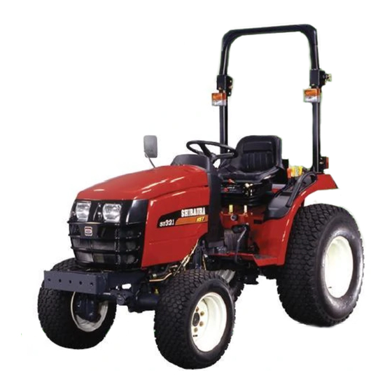
- Page 2 Introduction In order to refine the Shibaura tractor series furthermore, ST series tractors were developed this time. These are economical tractors provided with practical functions and high power. They meet users’ needs according to efficient and economical specifications requiring no after-care.
-
Page 3: Table Of Contents
INDEX Chapter 1 GENERAL ·································· 3 Chapter 3. Tractor main body ······················ 97 1-1 External Views ······················································ 4 3-1 Front Axle ··························································· 99 1-2 Specifications & Performance ································ 5 1. Sectional Views ··················································· 99 1-3 Precautions Before Servicing ································· 7 2. -
Page 4: Chapter 1 General
Chapter 1. GENERAL... -
Page 5: External Views
1-1 External Views T001 unit : mm Model ST 318 2728 2262 1042 1405 (9 × 3) ST 321 2728 2287 1138 1405 (9 × 3) ST 318 2728 2240 1188 1405 (HST) ST 321 2728 2240 1188 1405 (HST) ST 324 2728 2240... -
Page 6: Specifications & Performance
1-2 Specifications & Performances ST318 ST321 ST324 ST318 ST321 Model 9 × 3 9 × 3 Length (Lower Link holizontal) 2728 mm Top Steering Wheel 1233 mm 1265 mm 1290 mm Height Top ROPS 2240 mm 2262 mm 2287 mm... - Page 7 The ground speeds are engine speed at 2600 rpm with 8-16 Rear Tires On Model ST318 Manual Transmission. The ground speeds are engine speed at 2600 rpm with 9.5-16 Rear Tires On Model ST321 Manual Transmission. The ground speeds are engine speed at 2600 rpm with 29x12.00-15 Rear Tires On Model ST318/321/324 HST Transmission.
-
Page 8: Precautions Before Servicing
1-3 Precautions Before Servicing 1. Have the tractor washed clean and have the oil, fuel, and cooling water drained out depending on the work required. 2. Service shop should always be kept clean to prevent dust from rising and should be well lit. 3. - Page 9 METRIC BOLT TORQUE SPECIFICATIONS Coarse Thread Fine Thread Bolt Size Grade No. Kiro-gram Newton- Kiro-gram Pitch (mm) Newton Meters Pitch (mm) Meters Meters Meters 4T, 4.8 4.9-6.9 0.5-0.6 7T, 8T, 8.8 8.3-11.3 0.85-1.15 - - - - - - - - - - - - - - - 10T, 11T 11.7-15.7...
- Page 10 METRIC BOLT TORQUE SPECIFICATIONS Coarse Thread Fine Thread Bolt Size Grade No. Foot- Newton- Pitch (mm) Foot-Pounds Newton Meters Pitch (mm) Pounds Meters 4T, 4.8 3.6-4.3 4.9-6.9 7T, 8T, 8.8 6.1-8.3 8.3-11.3 - - - - - - - - - - - - - - - 10T, 11T 8.7-11.5...
-
Page 11: Sequence Of Dismantling The Tractor
1-5 Sequence of Dismantling the Tractor Flow chart Manual Transmission Model Hydrostatic Transmission Model Front axle Front axle Engine Engine Clutch case Clutch case Transmission Transmission (Front) Transmission (Rear) Rear axle Hydraulic cylinder case Rear axle Hydraulic cylinder case... - Page 12 1. ENGINE and HST UNIT REMOVAL (9 × 3 and HST) Disassembly 1. Steering wheel, instrument panel ① Remove the cap, retaining nut and spring washer. ② Pull the steering wheel. ③ Pull the instrument panel and disconnect the main wire harness and speed meter cable.
- Page 13 5. Air cleaner assembly ➀ Un tighten the hose band of the intake manifold. ➁ Remove the air cleaner assembly from the air cleaner support. T009 6. Radiator assembly ➀ Remove the radiator supports. ➁ Untighten the hose bands and disconnect the radiator hoses.
- Page 14 9. Fuel tank ➀ Disconnect the two fuel return hoses from the top of the fuel tank. ➁ Disconnect the fuel supply line from the fuel shut-off valve and drain the fuel from the tank into a clean container. ➂ Disconnect the electrical connectors from the fuel level sender unit.
- Page 15 12. Diverter valve ➀ Remove the banjo bolt and disconnect the sump return from the diverter valve disconnect the other end from the sump. ➁ Disconnect the system pressure line from the diverter valve and the lift cover. T017 13. Rubber, drive shaft ➀...
- Page 16 16. HST piping, oil cooler, oil filter with base (HST model) ➀ Remove the clamps for HST piping. ➁ Release the hose bands and remove the banjo bolts, pipings and oil filter with base. ➂ Remove the brackets and oil cooler form on the front axle support.
- Page 17 19. Power steering control valve, column ➀ Remove the cruise control assembly from the steering column on HST model. ➁ Remove the bolts and steering column from the clutch housing. ➂ Remove the power steering control valve from the column. T024 20.
- Page 18 22. HST unit ➀ Remove the damper bracket from front of the HST unit. ➁ Disconnect the shift link from the HST unit. ➂ Remove the HST unit from the extension housing. NOTE: Do not lose the O-ring when removing the unit from the extension housing.
- Page 19 2. TRANSMISSION REMOVAL (9 × 3) Disassembly 1. Seat · seat track · grip · lever guide ➀ Remove the seat and seat track assembly. ➁ Remove the grips from the hydraulic control lever, FWD control lever, transmission speed range lever, and transmission speed main change lever.
- Page 20 4. Fender, tool box, center frame ➀ Remove the fenders and frame:lower. ➁ Remove the clip pin and pin from the both brake levers to separate the hand brake wires. ➂ Remove the tool box and center frame. T033 5. Transmission cover plate ➀...
- Page 21 7. Suction, return tube ➀ Loosen the hose clamp, and remove the suction tube, from the filter. ➁ Remove the banjo bolt, with O-ring and remove the return tube. T037 ➂ Loosen the hose clamp and remove the banjo bolt and suction tube for HST.
- Page 22 9. Range gear change lever ➀ Drive out the roll pin from the range change lever. ➁ Remove the range change lever assembly on HST Model, and remove the range change lever assembly from the hydraulic lift cylinder housing on 9×3 Model. T041 T042 10.
- Page 23 ➃ Remove the retaining bolts and nuts securing the lift cover to the center housing. ➄ Using a hoist, remove the lift cover. NOTE: Use care when put the housing the range gears are installed bottom of the housing. T045 12.
-
Page 24: Installation And Trial Run
1) Liquid gasket and thread sealant (Loctite Safety Solvent) ➀ We recommend the liquid gasket sealer is SHIBAURA Part Code No. 095109062 or Three Bond No. 1104. ➁ Use care to not permit excess sealer to enter the inside of the housings or shift rod bores. - Page 25 4. HST cruise control rod ➀ Adjust the length of the cruise control rod as same as before disassembled length. If didn’t measure length, adjust it as shown. NOTE: If necessary, adjust the neutral position by tuenbackle. T051 5. Power steering piping Power steering pipings tightening torque to follows as illustration.
- Page 26 7. Steering wheel nut The nut for steering wheel is tightend to 3.0~3.4 N·m (0.3~0.35 kgf·m) T054 8. Battery cable ➀ Fit the positive battery cable first then the negative. T055 2. TRIAL RUNNING After overhaul engine it will need a trial run – Refer to the following 1.
-
Page 28: Chapter 2 Engine
Chapter 2. ENGINE Tractor Model Engine Model ST318 S753 ST321 S773 ST324 S773L... -
Page 29: Engine Sectional View
2-1 Engine Sectional View T100 T101... -
Page 30: Engine Specifications
2-2 Engine Specifications Model ST318 ST321 ST324 Specifications S753 S773 S773L 4-cycle diesel engine Type Cylinder arrangement Vertical in-line Combustion chamber type Whirl-chamber type No. of cylinders 75 mm × 72 mm 77 mm × 72 mm 77 mm × 82 mm... -
Page 31: Disassembly, Inspections And Reassembly
2-3 Disassembly, Inspection and Reassembly 1. DISASSEMBLY T102 Disassembly Order Parts Name Alternator Starting motor Oil filter Relief valve Oil level gauge · Gauge guide Engine stop solenoid · Seal washer Injection pipe Injection pump NOTE: 1. Remove the injection pipes and engine stop solenoid before remove the injection pump. 2. - Page 32 T103 Order Parts Name Return pipe Injection nozzle · gasket Oil pipe · Eye bolt · Seal washer Glow plug · Connector Thermo-sensor Oil pressure switch Head cover Rocker arm assembly NOTE: Draw out the roll pin (A) from the No. 1 rocker arm bracket, and remove the rocker arm shaft.
- Page 33 T104 Order Parts Name Fan holder · Fan pulley · V-belt · Cooling fan Water pump assembly · Thermostat · Gasket Hydraulic oil pump · Power steering oil pump Crankshaft pulley Timing gear case assembly NOTE: Remove the engine stop solenoid and injection pump assembly at first. Idle gear ·...
- Page 34 T105 Order Parts Name Oil pan · Gasket · Suction filter · Suction pipe Fly wheel Rear plate Oil seal Piston and connecting rod assembly NOTE: 1. Before extracting piston, remove the carbon deposit from the TDC in the cylinder. 2.
-
Page 35: Engine Main Parts
2. DISASSEMBLY AND INSPECTION OF ENGINE MAIN PARTS * Cautions before start 1) Check the cylinder block and cylinder head for wear, leakage and damage. 2) Remove deposit in oil holes of each part with air and check for clogging. 3) Wash each part well to remove dust, contaminated oil, carbon, and other foreign matter. -
Page 36: Cylinder Head Ass'y
2) Cylinder head ass’y Disassembly (1) Using a valve spring replacer, compress the valve spring to remove the valve cotter, retainer, spring and valve. (2) Remove the valve guide seal. 1. Valve guide seal 4. Valve 2. Spring 5. Valve cotter 3. - Page 37 ➃ Replace the valve if the clearance between the stem Clearance between valve stem and valve guide (mm) and guide exceeds the service limit. Intake valve Exhaust valve Standard Standard Service assembling Service limit assembling limit value value More than 0.045 –...
- Page 38 ➃ Coat the valve seat surface with compound and lap the contact surface turning the valve. ➄ Check that the valve contact surface is within the standard value and the contact position is even. ➅ When the cylinder head is replaced with new one, adjust the seat contact width and seat recess to the specified values with a seat cutter before lapping.
-
Page 39: Cylinder Block
3) Cylinder block Distortion on cylinder block top surface (mm) Standard assembling value Repair value Inspection and service Less than 0.05 More than 0.12 (1) Check for crack, damage and distortion on the top of the block in the same way as in the cylinder head. (2) Measurement of cylinder bore ➀... -
Page 40: Piston And Piston Ring
4) Piston and piston ring Disassembly (1) Remove the piston ring using a piston ring tool. (2) Remove the snap ring and extract the piston pin. Piston ring Piston pin T120 Inspection Clearance between cylinder and piston (mm) (1) Piston Standard Model Service limit... - Page 41 (2) Piston ring ➀ Replace worn out or damaged piston ring, if any. Piston ring end gap (mm) ➁ Insert a ring at a right angle to the least worn out Standard assembling skirt of a cylinder, measure the clearance of ring S753 Service limit value...
-
Page 42: Connecting Rod
5) Connecting rod Inspection (1) Check for torsion, parallelism and damage. Torsion and parallelism of connecting rod (mm) Measure the torsion and parallelism using a connecting rod aligner and correct or replace if the repair value is Standard Repair value exceeded. -
Page 43: Connecting Rod Metal
Reassembly (piston and connecting rod) (1) Heat the piston to about 100°C with a piston heater or the like and install it aligning the SHIBAURA mark in the piston and match mark at (A) of the connecting rod. (2) Care should be taken to the figure match mark at (A) of the connecting rod. -
Page 44: Of Bearing Holder
7) Disassembly, inspection and reassembly of bearing holder Disassembly and inspection Center bearing Model S753· S773 (1) Remove the bearing holder, and replace the metal if peeling, melting, uneven wear, or improper contact is Crankshaft center noticed. journal finishing Metal size Metal code No. -
Page 45: Crankshaft Bearing (Bush)
8) Crankshaft bearing (bush) Inspection (1) Check the bearing (bush) and replace if peeling, melting, uneven wear, improper contact, or other damage is notice. (2) Measure the oil clearance of the bearing (bush) and crankshaft journal using a cylinder gauge and micrometer. -
Page 46: Crankshaft
9) Crankshaft Inspection (1) To measure run-out of the crankshaft, support the Crankshaft run-out (mm) crankshaft using a V block as shown in the right figure, apply a dial gauge to the crankshaft center journal, read Standard assembling value Service limit the indication on the dial gauge rotating the shaft one turn gently. -
Page 47: Flywheel And Ring Gear
10) Flywheel and ring gear Inspection Check the ring gear and replace if damage or remarkable wear is noticed. When the wear is limited to a small area, remove the, ring gear, turn it about 90 degrees and shrinkage-fit to reuse it. To shrinkage-fit the ring gear, heat it to 120 –... -
Page 48: Oil Flow
13) Oil flow T140... -
Page 49: Oil Pump
14) Oil pump Disassembly Removal from engine (1) Remove the snap ring. (2) Take out the colar, spring and shim. (3) Take out the idle gear, vane, and oil pump cover together. (4) Extract the rotor and thrust washer. (5) Extract the oil pump cover from the idle gear. T141 1. -
Page 50: Water Pump Assembly And Thermostat
16) Water pump assembly and thermostat Disassembly (1) Remove the set plate gasket. (2) Remove the thermostat spring. 1. Water pump ass’y 2. Gasket 3. Set plate 4. Thermostat 5. Spring 6. Gasket NOTE: The pump main body is aluminum die cast and should be replaced as ass’y if subjected to water leakage or other troubles. -
Page 51: Radiator
17) Radiator Specifications and structure Structure Specifications (1) The radiator is provided with the plate fin having Fin type Corrugated superior anti-vibration characteristics. (2) The radiator cap is of the pressure type (sealing type) Cooling water volume 3.5 ℓ for higher cooling efficiency. Pressure valve starting... -
Page 52: Fuel Filter
18) Fuel filter Fuel passage Fuel passage The fuel flows as shown in the figure from the tank, pressurized by the injection pump to high pressure, and fed to the nozzle and injected to the combustion chamber. The fuel after lubricating the nozzle needle is returned to the tank through the overflow pipe. -
Page 53: Injection Pump
20) Injection pump Specification Engine Model Part Code No. Manufacturer and Injection Pump Type S753 131017310 094500 – 3730 S773 131017710 094500 – 7410 S773L 131017640 094500 – 6340 Disassembly, Inspection and Reassembly (1) Disassembly, inspection, and reassembly of injection pump. If the trouble has been verified to be in the injection pump, do not disassemble other than at shop specializing in this operation. - Page 54 Disassembly and inspection (1) Place the nozzle holder (body) in a vice and disassemble turning the nozzle nut. NOTE: Take care not to allow the needle valve to drop when removing the nozzle. (2) Wash the nozzle and needle valve and check for seizure and sticking of the nozzle and fuel leakage on the seat surface.
-
Page 55: Air Cleaner
22) Air Cleaner Structure and functions (1) The air cleaner is connected to the cylinder with the air cleaner hose. (2) The air cleaner is of the cyclone type incorporating filter element and removes dust from the intake air. Inspection and replacement (1) Take out the element every 100 –... -
Page 56: Engine Reassembly
3. ENGINE REASSEMBLY Cautions before assembly ★ 1. Wash parts to be installed. (Especially wash oil passage bearing, piston and cylinder bore carefully.) 2. Coat the sliding and rotating parts of the cylinder bore, piston, bearing and other parts with new oil before installing. 3. - Page 57 3. Oil seal 4. Rear plate NOTE: Apply the liquid gasket to around the M 10 screw holes for rear plate. Rear plate tightening torque: 46 ~ 54 N·m (4.7 ~ 55 kgf·m) 5. Fly wheel Align the hole to the roll pin on the crankshaft. Fly wheel tightening torque 69 –...
- Page 58 8 Oil pan Start tightening the bolts of the oil pan from the center, then tighten the opposing bolt on opposite side on the diagonal and specified torque. Oil pan tightening torque 10 – 12.7 N·m (1.0 – 1.3 kgf·m) 9 Oil level gauge and Gauge guide T158 Install the oil level gauge and gauge guide using 2...
- Page 59 NOTE: 1. Coat the rotor and vane both sides with grease before installing them. 2. Never turn the crankshaft until the timing gear case is installed. 3. Turn the oil pump cover clockwise and counterclockwise, fix the hole at the center of the spring pin inserting hole moving distance, and then install the gear case.
- Page 60 15 Injection pump assembly ➀ Fit the shim which has been removed at the time of disassembly, connect the control rack of the injection pump and link, and fix with the snap pin. ➁ Tighten the injection pump with bolts and nut. Injection pump tightening torque 5 ~ 7 N·m (0.5 ~ 0.7 kgf·m) T165...
- Page 61 Engine Model S753 and S773 Engine Model S773L Piston displacement to crankshaft angle Piston displacement to crankshaft angle (before TDC) (before TDC) (°) Displacement (°) Displacement (°) Displacement (°) Displacement 2.850 4.411 3.206 4.963 3.137 4.761 3.529 5.356 3.436 5.132 3.866 5.763 3.749...
- Page 62 20 Cylinder head <Models S753 and S773L> ➀ Position each of the pistons at top dead center and, using a dial indicator, determine the distance each piston projection above the face of the block. NOTE: Measure each of the pistons while holding a slight down pressure on the piston.
- Page 63 21 Oil pipe Eye bolt tightening torque 10 ~ 13 N·m (1.0 ~ 1.3 kgf·m) T171 22 Push rod Rocker arm ass’y Install the push rod and rocker arm ass’y Rocker arm ass’y tightening torque 20 ~ 25 N·m (2.0 ~ 2.5 kgf·m) 23 Valve clearance adjustment T172 Untighten the nut of the intake and exhaust valves and...
- Page 64 25 Water pump ass’y · Radiator hose Water pump ass’y Radiator hose (upper) Radiator hose (lower) 26 Glow plug · Connector T174 Model Glow plug tightening torque S753·S773 15 – 20 N·m (1.5 – 2.0 kgf·m) S773L 8 – 15 N·m (0.8 – 1.5 kgf·m) 27 Oil pressure switch Oil pressure switch tightening torque 15 ~ 20 N·m (1.5 ~ 2.0 kgf·m)
- Page 65 31 Drive gear assembly, Hydraulic oil pump and power steering oil pump ➀ Install the drive gear assembly to the hydraulic pump and then install them to the gear case. ➁ Install the power steering oil pump to front of the gear case.
-
Page 66: Electrical Units
2-4 Electrical Units 1. ALTERNATOR 1) Specifications and construction Clockwise Rotating direction (when viewed from pulley side) 13.5 V speed Less than 1350 rpm More than 10A (at 14V, 2500 rpm) Output current More than 40A (at 14V, 5000 rpm) T179 2) Cautions for handling Care should be taken to the following points when handling the alternator. - Page 67 3) Disassembly T180 Reference Figure 180T. (1) Pulley Loosen and remove the pulley nut (1) with a box wrench while the hexagonal section of the pulley shaft is held firmly with STT. (STT stands for Service Tester & Tool.) (2) Rear end cover Remove 3 nuts (2) holding the rear end cover (4) and a nut (5) at B terminal and remove rear end cover (4).
- Page 68 (5) Rectifier Remove four screws (11) holding rectifier (8) and lead wire form stator (12). (6) Bushing Remove bushing (13) and 4 bolts (14) which are holding the drive end frame (15) and rear end frame together. NOTE: Do not stretch the stator wire when the bushing (13) is removed.
- Page 69 4) INSPECTION REPAIR EACH COMPONENT (1) Pulley Check for fan belt slippage. (2) Fan Check for deformation. (3) Ball Bearing Rotate it by hand and check for resistance or noise in movement. T185 Ball Bearing Inspection (4) Stater ● Resistance between each phase (between each end of the lead wire and neutral point) shall be less than 1Ω.
- Page 70 ● Insulation resistance between slip ring and core pole. More than 0.1 MΩ when measured with a 500 V megger. ● Slip Ring Outer Diameter Example: Standard 14.4 mm Limit of use 14.0 mm (6) Rectifier The circuit diagram of the rectifier is shown in Figure T190.
- Page 71 5) ASSEMBLY Assembly is the reverse of the disassembly procedure. Be care ful of the following points. (1) Brush When a new brush is installed, it should protrude from brush holder by 1.5 mm. T192 Brush Installation (2) Rotor Before the rotor is installed, the brush should be pushed into the brush holder.
- Page 72 (2) Check for alternator output current Turn headlight high-beam on (to put a load on the alternator) and take the output current reading while maintaining a speed of 2000 rpm. If the current reading is greater than the standard, the alternator is in good condition. 7) Trouble Shooting.
- Page 73 (3) Troubleshooting when charge lamp is turned on while the engine is running. Improper contact in alternator connector (B, IG and L) or disconnection in wiring (including IG circuit fuse) on vehicle or short circuit. Repair fault and start engine. Charge lamp is turned on.
- Page 74 8) Care in Handling Charging System. (1) Pay attention to battery polarity and absolutely refrain from making a wrong connection. If it is wrongly connected, the battery will be short-circuited by the diode where it admits and enormously large current which will destroy the diode and regulator and burn the wiring harness out.
-
Page 75: Starting Motor
2. STARTING MOTOR (TYPE 128000-0101 NIPPON DENSO) 1) Specifications Continuous operation 30 seconds (max) Output 1.0 kW Weight 3.85 kg Rotating direction Clockwise (viewed from pinion) Clutch type Overrunning Engaging type Magnetic shift Pinion ejecting voltage 8 volts T195 1. Brush spring 6. - Page 76 3) Disassembly, inspection and reassembly T197 NOTE: ➀ Remove the connecting lead which connects the 1. Do not damage the clutch bearing. magnetic switch and the yoke. 2. Never disassemble the magnetic switch. (If the switch is found to be defective, replace as a ➁...
- Page 77 Inspection (1) Armature ➀ Check the insulation between the commutator and the armature with 500 V megger. The armature is normal if there is resistance of more than 0.1 mega ohm. ➁ Layer insulation test (short-circuit test) Setting the armature on the growler tester, check the layer insulation.
- Page 78 (3) Field coil ➀ Continuity test Using a circuit tester (× 1 ohm range), check continuity among the C terminal, field coil and brush. If there is continuity, the field coil is in satisfactory condition. T202 ➁ Insulation test With a 500 V megger, check insulation between the field coil brush and yoke.
- Page 79 (5) Clutch A. If the gear is excessively worm or damaged, replace it with new. B. Clutch operation ➀ The clutch should lock the gear when turning it to the normal revolving direction. And, it should allow the gear to turn freely when turning the gear in reverse direction.
- Page 80 4) Troubleshooting (1) The pinion does not move when the key switch is set to start position. Trouble Case Remedy Wiring Disconnection, loosened terminals of the battery or switch Repair and retighten. Key Switch Insufficient contact. No current flows. Repair the contact area or replace Pinion shaft helical spline is stucked and the pinion does not Starting motor Replace or repair...
-
Page 81: Glow Plug
(5) After the engine starts, the motor does not stop when the key switch is released. Trouble Case Remedy Key switch Faulty switch Replace Magnetic switch Faulty magnetic switch Replace 3. GLOW PLUG Ultra high speed heating type, IQS purpose glow plugs are used in this engine. For IQS system, refer to (Section 3-8 Electrical equipment and accessory). -
Page 82: Battery
6. BATTERY 1) Specifications Type 12 V Specific gravity of electrolyte 1.28/20°C when fully charged Capacity 36 AH Charging current 6.5 ampere (normal charging) 2) Specific gravity of electrolyte and charging condition The specific gravity of electrolyte decreases approximately Specific gravity Discharged Residual capacity lineally in proportion to the discharged electricity of... -
Page 83: Fusible Link
8. FUSIBLE LINK Inspection The fusible link is installed between the battery and alternator and key switch to prevent burning of electrical units and wiring harness to which large current flows instantaneously. NOTE: 1. When the fusible link burns after replacement, short circuit of wiring, etc. -
Page 84: Trouble Shooting
2-5 Trouble Shooting Trouble Cause Remedy Defective key switch Connect or correct contact points propely. Insufficient charging or completely discharged Charge. battery. No fuel. Replenish the fuel. Air mixed in the fuel system. Correct points allowing the air to enter the fuel. - Page 85 Trouble Cause Remedy Improper color of Too much engine oil. Check and adjust the quantity. engine exhaust Too low viscosity of engine oil. Check and change. (white or blue) Improper injection timing. Too late. Correct. Improper fuel. Check and change. Improper engine Excessive fuel injection.
- Page 86 2-6 Engine Maintenance Standards Table S753 ENGINE (ST318) Unit for values without unit in the column of inspection item is mm. Standard To be Allowable Unit Part Inspection Items Standard Value Remarks Dimension Repaired Limit Compression pressure of cylinder More than 2.94 Less than 2.45...
- Page 87 Standard Allowable Unit Part Inspection Items Standard Value To be Repaired Remarks Dimension Limit Twist between small and large end holes (per 100 Less than 0.08 More than 0.2 Straightness at 100 mm between small and large Less than 0.05 More than 0.15 end hole Front-to-rear clearance between connecting rod...
- Page 88 Standard Allowable Unit Part Inspection Items Standard Value To be Repaired Remarks Dimension Limit When Valve clearance (Intake/exhaust) cooling temperature At 30.4 mm Spring strength (kgf) Less than 7 compressed length Free height 33.5 Valve spring Less than 1.2 T215 Open-Before T.D.C 13°...
- Page 89 Standard Allowable Unit Part Inspection Items Standard Value To be Repaired Remarks Dimension Limit Type 093500 – 3320 DENSO 11.76 11.27 – 12.25 Injection pressure MPa (kgf/cm (120) (115 – 125) Angle of injection direction 4° Cooling method Water colded, forced circulation Coolant capacity (ℓ) 80 –...
- Page 90 S773 ENGINE (ST321) * Unit for values without unit in the column of inspection item is mm. Standard To be Allowable Unit Part Inspection Items Standard Value Remarks Dimension Repaired Limit Compression pressure of cylinder More than 2.94 Less than 2.45 Engine 200 MPa (kgf/cm (More than 30)
- Page 91 Standard Allowable Unit Part Inspection Items Standard Value To be Repaired Remarks Dimension Limit Twist between small and large end holes (per 100 Less than 0.08 More than 0.2 Straightness at 100 mm between small and large Less than 0.05 More than 0.15 end hole Front-to-rear clearance between connecting rod...
- Page 92 Standard To be Allowable Unit Part Inspection Items Standard Value Remarks Dimension Repaired Limit When Valve clearance (Intake/exhaust) cooling temperature At 30.4 mm Spring strength (kgf) Less than 7 compressed length Free height 33.5 Valve spring Less than 1.2 T219 Open-Before T.D.C 13°...
- Page 93 Standard Allowable Unit Part Inspection Items Standard Value To be Repaired Remarks Dimension Limit Type 093500 – 3320 DENSO 11.76 11.27 – 12.25 Injection pressure MPa (kgf/cm (120) (115 – 125) Angle of injection direction 4° Cooling method Water colded, forced circulation Coolant capacity (ℓ) 80 –...
-
Page 94: S773L
S773L ENGINE (ST324) Unit for values without unit in the column of inspection item is mm. Standard Allowable Unit Part Inspection Items Standard Value To be Repaired Remarks Dimension Limit Compression pressure of cylinder More than 2.94 Less than 2.45 Engine 200 MPa (kgf/cm (More than 30) - Page 95 Standard Allowable Unit Part Inspection Items Standard Value To be Repaired Remarks Dimension Limit Twist between small and large end holes (per 100 Less than 0.08 More than 0.2 Straightness at 100 mm between small and large Less than 0.05 More than 0.15 end hole Front-to-rear clearance between connecting rod...
- Page 96 Standard To be Allowable Unit Part Inspection Items Standard Value Remarks Dimension Repaired Limit When Valve clearance (Intake/exhaust) cooling temperature At 30.4 mm Spring strength (kgf) Less than 7 compressed length Free height 33.5 Valve spring Less than 1.2 T223 Open-Before T.D.C 13°...
- Page 97 Standard Allowable Unit Part Inspection Items Standard Value To be Repaired Remarks Dimension Limit Type 093500 – 3320 DENSO 11.76 11.27 – 12.25 Injection pressure MPa (kgf/cm (120) (115 – 125) Angle of injection direction 4° Cooling method kgf/cm Water colded, forced circulation Coolant capacity (ℓ) 80 –...
-
Page 98: Chapter 3. Tractor Main Body
Chapter 3. TRACTOR MAIN BODY... - Page 99 NOTES: Precautions before start 1) Wash each part sufficiently and remove dust, liquid packing, gasket, etc. 2) Store bolts and O-rings in order not to be confused at the time of reassembly since their sizes vary depending on positions of use. 3) Handle gears carefully not to damage and store carefully so that they are not reassembled in incorrect direction.
-
Page 100: Front Axle
3-1 Front Axle 1. SECTIONAL VIEWS Wheel drive Viewed from the Front T401 2. DISASSEMBLY, INSPECTION, REASSEMBLY OF FRONT AXLE 1) Power Steering Cylinder Disassembling procedure 1 Power steering cylinder Remove the power steering cylinder with hoses from the front axle. T402... - Page 101 2 Tire · Front wheel support ➀ Remove the right and left tires. ➁ Remove the front and rear bearing holders and separate the front axle ass’y and front wheel support. 3 Case cover (final) T403 Remove the wheel shaft and final gear (bevel) together. T404 4 Transmission case (final) Remove the bolts of the arms (knuckle) and take out...
- Page 102 6 Arm (knuckle) king pin Remove the right and left arms. T407 7 Transmission case (idler) · King pin Remove the right and left transmission cases and king pin as a set. T408 8 Wheel shaft case (left) NOTE: When any shims have been installed between the case and bearing, note their thickness and quantity and take care not to miss them.
- Page 103 10 Differential shaft (left) Differential ass’y T411 11 Final pinion (right) Differential shaft (right) Extract the final pinion (right), bearing and differential shaft (right). NOTE: When any shims have been inserted between the case and bearing, note their thickness and quantity and take care not to miss them.
- Page 104 14 Transmission case ass’y (final) ➀ Take out the final pinion, bearing, and drive shaft. ➁ Remove the oil seal and taper bearing. T415 15 Transmission case ass’y (idler) ➀ Remove the king pin and O-ring ➁ Remove the final pinion (ildler). ➂...
- Page 105 2. Casing Replace the bush if the play of the pivot shaft exceeds the repair value. Clearance between pivot shaft and bush (mm) Standard Repair value assembling value T418 Front side 0.02 – 0.2 0.35 Rear side 0.02 – 0.16 0.35 T419 3.
- Page 106 6. Differential ass’y Refer to paragraph of transmission (rear differential). Components 1. Bearing (6305NR) 2. Spring pin 3. Pinion shaft 4. Bolt 5. Lock washer 6. Differential cage 7. Ring gear 8. Differential gear 9. Thrust washer 10. Differential pinion 11.
- Page 107 Reassembly 1. Reassembly of drive pinion (1) Be careful about the direction of the oil seal. (Position the seal lip to the oil side and fit under pressure 2 mm inward from the case end.) (2) Tighten the nut and measure the starting load (preload).
-
Page 108: Wheel Alignment
Swing angle 29±1mm 4°30' (2) If stopper bolt top surface has worn out unevenly, T428 replace the bolt. 4. FRONT WHEEL 1) Specifications ST318 ST321·ST324 Tire size Rim size Tire size Rim size Agriculture 5 – 12 3.00D – 12 6 –... -
Page 109: Clutch
3-2 Clutch 1. SINGLE CLUTCH 1) Specifications and sectional view Type Dry, single-plate foot-stepping type Rivet recess 1.2 mm No. of clutch plates 1 (facing; 2) Operating method Mechanical Disk Release lever height ∅184 × ∅127 × 8.1 ± 0.3 mm (O.D. - Page 110 2) Disassembly, inspection and reassembly of clutch (Refer 1-5, Removal of outside, for the clutch case separating method.) Disassembling procedure 1 Release bearing Release hub Clutch shaft Clutch fork For manual transmission ➀ Remove the return spring and extract the release hub and bearing together frontward.
- Page 111 2. Clutch disk COMPL (1) Measure the wear of the facing (rivet recess). Replace if the rivet recess is less than 0.3 mm. (2) Replace the clutch disc compl if the facing is hardened or deflected due to seizure. (3) Wash in gasoline if oil is sticked. (4) Replace the clutch disc compl if the spline is worn T436 out or disk run-out is observed.
- Page 112 5. Drive shaft If the spline area is worn out unevenly or damaged, replace the drive shaft. (Refer to Disassembly of Transmission 1) NOTE: Check the clutch disk spline area at the same time. T440 6. Flywheel (1) Check for cracks and uneven wear and correct the clutch disc contacting surface if the damage is insignificant.
- Page 113 NOTE: 1. Drive in the bush so that it becomes level with the boss end surface Ⓐ 2. Align the bush hole and grease nipple, hole (arrow mark Ⓑ in the right figure). T444 8. Oil seal for drive shaft (reverse gear shaft) When replacing the oil seal, press in oil seal facing to the clutch case shown in the right figure.
-
Page 114: Troubleshooting Of Clutch
2. TROUBLESHOOTING OF CLUTCH Condition Cause Remedy 1. Slippery clutch (1) Does not speed up. (1) No play in the clutch pedal. (1) Adjust the free-play to 20 – 30 (2) Does not accelerate rapidly. (2) Oil or grease sticked to the facing. mm on the pedal tread. -
Page 115: Transmission
3-3 Transmission 1. 9 × 3 MANUAL TRANSMISSION 1) Sectional view Without Mid PTO T447 With Mid PTO T447... - Page 116 Top View T448 2) Disassembly, Inspection and Reassembly of Transmission Disassembling procedure 1 Change lever (Main shift) ➀ Remove the two nuts and change lever. ➁ Remove the nut and rod from the change lever case. T449 2 Change lever case Shifter rods Shifter forks Shift arm...
- Page 117 ➃ Remove the switches form each side and slide the pins and steel balls out of the cover. ➄ Drive out the spring pins form the shifter forks and slide the shifter rods forward out of the cover T451 driving the plugs out at the same time. ➅...
- Page 118 ➈ Place a wooden block between the shift arm and the cover. ➉ Drive the spring pins from the shift arms and withdraw the shift arm, guide form the cover. T455 Components 1. Bolt 15. Shaft 30. Bush 2. Seal washer 16.
- Page 119 5 Main shaft ➀ Remove the snap ring at the shaft rear end. ➁ While sliding the main shaft frontwards, remove the snap ring on the shaft rearwards from the groove. ➂ Extract the shaft frontwards and take out the fixed gear, collar, and slide gear.
- Page 120 8 Counter shaft ➀ Remove the snap ring on the shaft rearwards and move the fixed gear fully rearwards. ➁ Move the shaft together with the bearing frontwards and take out the bearing from the shaft. ➂ Move the shaft furthermore frontwards. When it comes out of the drive pinion at the rear, take out the shaft from above the case.
- Page 121 10 Differential ass’y Take out the differential ass’y 11 Drive pinion T466 ➀ Remove the snap ring. ➁ Straighten the bent claws of the lock nut, and remove the nut. ➂ Remove the snap ring at the rear of the 4WD fixed gear from the groove.
- Page 122 13 PTO counter shaft – 1-speed PTO – ➀ Extract the counter shaft (rear) rearwards. ➁ Extract the counter shaft (front) front wards and take out the slide gear, thrust washer, needle bearings and counter gear. ➂ If necessary, remove the bearing from the shaft and case.
- Page 123 16 Shifter rod Shifter forks Shifter arms (PTO and Range shift) ➀ Drive out the spring pins and take out the range change lever. ➁ Drive out the spring pin and take out the PTO change lever. ➂ Remove the set bolt. ➃...
- Page 124 18 Mid PTO counter shaft (Option) ➀ Pry the sealing plug out from the rear end of the case. ➁ Remove the snap ring at the rear of the case and remove the snap ring in the front of the shaft from the groove.
- Page 125 20 Transmission for range shift ➀ Remove the transmission ass’y form below the hydraulic cylinder case. ➁ Remove the plate at the rear of the transmission case. ➂ Extract the counter shaft frontwards and take out the counter gear, needle bearing, collar, and thrust washer.
- Page 126 3. Clearance between shifter fork and slide gear Replace shifter fork and slide gear if the service limit is exceeded. Clearance between shifter fork and slide gear (mm) Assembling standard value Service limit 0.1 – 0.3 T483 4. Differential (1) Check each gear and replace it if damage is significant.
- Page 127 (5) Backlash of differential gear and differential pinion ➀ Insert 2 fuses at opposing positions between the Backlash of differential gear and differential pinion differential gear and differential pinion and turn the (mm) differential gear. Assembling standard value Service limit ➁...
- Page 128 6. Shifter ➀ Wear and damage of shifter rod groove ➁ Tension and breakage of detained spring ➂ Wear of each shifter fork ➃ Wear and damage of steel ball T493 7. Oil seals, O-rings, and gaskets. Replace the oil seals, O-rings and gaskets with new ones.
- Page 129 Assemble Assemble units in the reverse order to disassembly, taking care to the assembling procedure below. Assemble the shafts in the order of ➀ shifter rod, ➁ PTO shaft, ➂ drive pinion, counter shaft, ➃ drive shaft (reverse gear shaft), and ➄ main shaft. NOTE: Install the shift guides and shift arms at first in the housing.
- Page 130 4 Drive pinion ➀ Adjust the preload of the drive pinion at the specified value by tightening a new lock nut. Preload (on the outer periphery of spline) 68.6 – 88.2 N (7 – 9 kgf) ➁ Drive in the lock for the lock nut positively. T500 5 Thrust washer Install the thrust washer facing the oil groove toward...
- Page 131 7 Transmission for range shift Use care to gearing of each gear when install the cylinder case Ass’y. T503 Components 1. Transmission ass’y (Range shift) 2. Hydraulic cylinder case T504...
-
Page 132: Hydrostatic Transmission
2. HYDROSTATIC TRANSMISSION (1-SPEED PTO, MID PTO) 1) Sectional view T505 T506... - Page 133 2) Specifications Name Biaxle type HST Model HVFD16F-R28-P-LT Max. input speed 2800 rpm Output speed 0 – 2950 rpm (at 9.8 MPa (100 kgf/cm Pump swash plate tilting angle 0° - ±16° Max. working pressure 27.4 MPa (280 kgf/cm )(Relief set pressure) Charge circuit pressure 0.42 –...
- Page 134 (2) HST main body T508 1. Pump Case 17. Holder 33. Gasket 49. Pin 2. Motor Case 18. Plate 34. Gasket 50. O-Ring 3. Port Block 19. Cover 35. O-Ring 51. Backup Ring 4. Charge Pump Case 20. Trochoid Rotor S/A 36.
- Page 135 (3) Hydraulic circuit T509 1. HST unit 7. Oil pipe (to HST unit) 2. Oil cooler 8. Suction filter 3. Oil pipe (to cooler from HST unit) 9. Foot pedal 4. Oil pipe (from cooler) 10. Oil pipe; check valve 5.
- Page 136 4) Operation (1) Variable type pump T511 T510 1. Shaft (input) 2. Swash plate 3. Cylinder block 4. Piston 5. Valve port plate Above figure shows the rotary parts of a swash plate type axial piston pump. Nine pistons are incorporated in the cylinder block.
- Page 137 (2) Fixed type motor T515 T514 1. Shaft (output) 2. Swash plate (fixed) 3. Cylinder block 4. Piston 5. Valve plate Above figure shows the rotary parts of the axial piston motor. Nine pistons are incorporated in the cylinder block. The valve plate having 2 crescent-shaped passages Ps and Pd is in contact with one end of the cylinder block.
- Page 138 5) Oil flow (1) Neutral Even when the input shaft from the engine is rotated, the variable displacement pump does not start the pumping operation. Therefore, no oil is supplied to the motor from the pump and the output shaft on the transmission side does not rotate.
- Page 139 (2) Forward By depressing the HST pedal to the forward side, the variable displacement pump starts the pumping operation and discharges the oil. The discharged oil is supplied to the fixed displacement motor and output shaft is rotated. The high pressure side check valve is closed under the pressure of the oil and the low pressure relief valve is opened under the charge pressure.
- Page 140 (3) Reverse By stepping the HST pedal to the reverse side, the variable displacement pump starts pumping operation and discharges oil. The discharged oil is supplied to the fixed displacement motor and the output shaft rotates reversely to the forward operation.
- Page 141 6) Disassembly, inspection and reassembly (1) Disassembly of hydrostatic transmission Disassembling procedure 1 HST unit HST pedal Shift link ➀ Remove the control lever from the HST unit (trunnion shaft) and separate the damper from below of the unit. ➁ Remove the HST unit from the front of the transmission case (front).
- Page 142 3 Drive shaft (traveling) ➀ Extract the shaft rearwards from the transmission case (front) and take out the counter gear, needle bearing, collar and thrust washer. ➁ If necessary, remove the bearing at the rear end of the shaft and bearing and oil seal in the case. T522 4 Bearing holder ➀...
- Page 143 6 4WD drive shaft ➀ Remove the 4WD shifting system case cover form the side of the transmission case. (See the paragraph of 9 × 3 manual transmission.) ➁ Remove the snap ring at the rear end of the shaft and take out the slide gear.
- Page 144 9 Drive pinion ➀ Remove the snap ring. ➁ Straighten the bent claws of the lock nut and remove the nut. ➂ Extract the drive pinion rearwards and take out the fixed gear, snap rings and slide gear (range gear). ➃...
- Page 145 12 Mid PTO counter shaft ➀ Drive out the spring pin from the counter shaft. ➁ Slide the shaft frontwards and remove the thrust washers, counter gear and needle bearings from the shaft. ➂ Extract the shaft frontwards. T534 Components 1.
- Page 146 14 Differential ass’y ➀ Heat the bolts head by burner and remove the bolts, and separate the ring gear and differential cage. ➁ Remove the clip and take out the gear and shaft in the differential cage. (See the paragraph of 9 × 3 manual transmission disassembly.) T537 15 Gear case (Mid PTO)
- Page 147 17 Mid PTO shaft Mid PTO shifter ➀ Pry the sealing plug out and remove the snap ring from the rear end of the case. ➁ Drive out the shaft rearwards and take out the slide gear. ➂ If necessary, remove the bearing and oil seal from the shaft or case.
- Page 148 Refer to the paragraph of assembly of 9 × 3 manual transmission. 1. Shift guide (PTO & range shifter) tightening torque 2. Drive pinion preload 3. Thrust washer installing direction Assembling procedure 1 Mid PTO case ➀ Check shaft end play using a dial indicator. If end play is more than 0.5 mm, adjust the end play by shims.
- Page 149 (3) Disassembly of HST unit Disassembling procedure 1 Pump ➀ Remove the socket head bolts (4 pcs), and remove the pump case spring, valve and gasket from the port block. 1. Socket head bolt 2. Port block 3. Pump case T547 NOTE: Once the pump ass’y is separated from the port block the charge pump relief valve...
- Page 150 NOTE: Use care not to lose the three pins when removing the cylinder block and piston ass’y. 1. Pin T551 ➃ Remove the thrust plate from the swash plate. (When it is difficult to remove, raise the thrust plate using a L-shaped rod.) 1.
- Page 151 ➃ Slide the cylinder block and piston ass’y from the motor of the shaft. 1. Cylinder block 2. Piston ass’y 3. Shaft NOTE: Use care not to lose the three pins when T555 removing the cylinder block and piston ass’y. 1.
- Page 152 ➆ Tap the shaft from the front side and remove it together with the bearing and snap ring from the case. 1. Shaft 2. Bearing 3. Case T559 3 Port block ➀ Remove the right and left plugs and take out the check valve (poppet, spring) from the port block.
- Page 153 4 Charge pump ➀ If necessary, unscrew the holder and remove the oil seal. ➁ Remove the socket head bolts (3 pcs) and take out the pump case. ➂ Remove the trochoid rotor, key, O-rings and plate from the shaft. T562 5 Pump shaft ➀...
- Page 154 ➃ Take out the swash plate from the case. T566...
- Page 155 (4) Inspection and reassembly of HST unit Inspection 1 Piston ass’y ➀ Replace if the play at the piston and shoe caulking area exceeds the service limit. Assembling standard value Service limit 0.03 mm More than 0.2 mm T567 ➁ Replace if the diameter clearance between the piston and cylinder block exceeds the service limit.
- Page 156 Reassembly Reassembly units in the reverse order to disassembly taking care of the following points. After completion of reassembly, rotate the input, output, and trunnion shafts respectively to check for smooth operation. T571 1. Tightening torque at each part Tightening torque Part N·m (kgf·m) ➀...
- Page 157 4. Install the cylinder block ass’y to the shaft holding the assembling jig by fingers. 1. Assembling jig 2. Cylinder block ass’y NOTE: 1. If the assembling jig is not held by fingers, the pin may drop off. 2. After installing the cylinder block ass’y, confirm that there is no pin on the shaft, assembling jig surface or in the case (since the pin condition cannot be directly confirmed).
- Page 158 7) Adjustment (1) Pressure Check procedure 1. Pressure adjustment of high pressure relief valve ➀ Set the range transmission lever at “H” (after starting the engine). ➁ To prevent the tractor rushes out at the time of measurement, raise the rear wheels using stable bases (it is more recommendable to remove the rear wheels).
- Page 159 2. Check of pressure of low pressure relief valve. (charge pump pressure) ➀ Set the range transmission and HST pedal at the neutral position. ➁ Remove the top cover of the transmission case and remove the eye bolt of the right side oil pipe. 1.
- Page 160 (2) Link system Check procedure 1. Adjustment of control rod and pedal stop ➀ Adjust the length of the control rod, from the turnbuckle top end to the bottom rod end center, to 137 mm. ➁ Adjust the length from the top of the turnbuckle to the bottom of the spring holder to 26 mm.
- Page 161 8) Trouble Shooting Replace the HST main body, if defective, as an ass’y as a rule. Condition Possible cause Remedy 1. Output shaft fails to rotate 1. Improper operation of HST Check the trunnion shaft movement and replace the when the HST pedal is set at pump or motor.
-
Page 162: Change Lever Linkage
3-4 Change Lever Linkage 1. MAIN SHIFT CHANGE LEVER, RANGE SHIFT CHANGE LEVER, REAR PTO CHANGE LEVER, MID PTO CHANGE LEVER AND 4WD CHANGE LEVER Remove the grips, rubber boot, lever guide, seat, seat track to refer to “1-5, sequence of Dismantling the tractor “in Chapter 1. - Page 163 2) Range shift change lever, Rear PTO change lever, Mid PTO change lever and 4WD change lever T588...
-
Page 164: Real Axle And Brake
3-5 Real Axle and Brake 1. SPECIFICATIONS AND SECTIONAL VIEW Style Internal sliding mechanical style Type Wet, multiple plate type (complete water proof) Lining Cellulose fiber Brake By expansion or contraction of brake adjustment Operation 2 rear wheel braking (independent right and left braking possible) T589 2. - Page 165 Disassembling procedure 1 Differential lock clutch Differential lock fork Differential lock pedal Shift arm ➀ Extract the differential lock clutch and fork from the differential shaft. Remove the spring from the pin. ➁ Drive out the spring pin, separate the differential pedal and shift arm and take them out of the case respectively.
- Page 166 4 Final gear Remove the snap ring (Ø40) of the wheel shaft and take out the final gear from the shaft. T595 5 Differential shaft ➀ Remove the differential shaft from the case. ➁ If necessary, remove the bearing (6306) and oil seal.
- Page 167 Inspection and service ➀ Disk Measure the lining thickness and replace if the measurement is below the service limit. Standard dimension Service limit 4.0 mm 3.7 mm T598 ➁ Stator Replace the stator if the lining-contact surface is roughened or the difference of level height is more than 0.1 mm.
-
Page 168: Brake Adjustment
• Adjust the wheel shaft end play to less than 0.5 mm by shims. Shim part number t = 0.2 mm 199280760 t = 0.5 mm 199280770 T602 3. BRAKE ADJUSTMENT Confirm that the right and left pedals work sufficiently and adjust the play to the standard value by means of the right and left brake rods. -
Page 169: Troubleshooting
3) Adjustment of wheel track (Option) The wheel track can be adjusted in 7 stages by changing the rim positions and interchanging the tires. NOTE: Bolts are apt to be loosened here. Tighten each bolt positively. T604 5. TROUBLESHOOTING Condition Cause Remedy 1) Insufficient return of the brake... -
Page 170: Hand Brake
6. HAND BRAKE 1) Components T605 1. Bracket 9. Brake Switch 2. Hand brake 10. Nut 3. Bolt 11. Pin 4. Cover 12. Washer 5. Wire 13. Split Pin 6. Wire 14. Bolt 7. Wire Holder 15. Nut 8. Washer... - Page 171 2) Disassembly, inspection and reassembly Disassembly ➀ Remove the cover. ➁ Untighten the lock nut of each wire. ➂ Remove the split pin and flat head pin. ➃ Remove the wire ass’y, L.H., and R.H. ➄ Remove the U nut and disconnect the wire ass’y from the hand brake. ➅...
- Page 172 3) Adjustment Adjustment procedure NOTE: ➀ Be sure to adjust the hand brake ass’y after reassembly. ➁ After adjusting the play of the foot brake, adjust the hand brake. ➀ Confirm that the hand brake lever, 1, is at the lowermost position. ➁...
-
Page 173: Steering And Linkage
3-6 Steering and Linkage 1. EXTERNAL VIEW T608 2. SPECIFICATIONS Discharge quantity (cc/rev) 1. Oil pump Rotating direction Counterclockwise viewed from shaft side 2. Steering Type Full hydraulic type (non load reaction type) Stroke (mm) 3. Steering cylinder Bore (ø) Adjusted flow rate (ℓ/min) 4. - Page 174 3. POWER STEERING CONTORL VALVE 1) Each parts list T609 1. Dust seal 19. Flat spring 2. Spring retaining ring 20. Pin 3. P port check connector 21. O-ring 4. O-ring 22. Spacer plate 5. Oil seal 23. Drive 6. Needle bearing kit 24.
-
Page 175: Relief Valve
2) Structure and function of each part 1. Spool and sleeve ➀ The spool and sleeve are rotary valves to change the direction or combination of the oil passage. Three combinations are possible (neutral, right steering and left steering) by handle operation. ➁... - Page 176 3) Oil Flow 1. At neutral The oil fed by the oil pump under pressure enters the housing from the port. P. Neutral port is provided on the periphery of the sleeve which leads to the groove of the spool. The oil passes through the cavity of the spool, notches of the spool and sleeve, and port T and is returned to the tank.
- Page 177 2. Left turn When the steering wheel is turned counterclockwise from the neutral position, the spool groove is turned counterclockwise and deviated from the hole and groove of the sleeve. At this condition, the oil passes through the spool groove and spool hole, and is supplied to gerotor. The gerotor is rotated counterclockwise, the oil is discharged through the sleeve hole and spool groove, fed to the cylinder from the port L, and the wheels are turned to the left.
- Page 178 3. Right turn When the steering wheel is turned clockwise from the neutral condition, the spool is deviated rightwards from the sleeve. The oil passes through the holes and grooves of the sleeve and spool and is supplied to gerotor. The Gerotor is turned clockwise and oil is discharged through the holes and grooves of the sleeve and spool, and fed under pressure to the cylinder form the port R.
- Page 179 4. At emergency (engine stop) No oil is supplied from the oil pump at emergency. If the steering wheel is turned counterclockwise at this condition, the Gerotor is rotated by the force of the operator. Resultantly the passage inside becomes negative pressure, and the oil from the oil tank moves the check valve bottom and is supplied.
- Page 180 4) Disassembly and Reassembly of control Valve (1) Disassembly Disassembly 1. Place the end cap to a vice facing the gerotor upward, 6. Pull out the drive (9). inserting a copper plate or the like. 7. Remove the spacer plate (11) and O-ring (21). 8.
- Page 181 11. Remove the retaining ring (15) and pin (12) from the spool and sleeve assembly. 15. Remove the retainer screw (24), retainer pin (25) and 12. Slide out the spool (14) a little from the sleeve (13) steel ball (26) from the housing. and remove the centering springs (16) and flat springs 16.
- Page 182 (2) ASSEMBLY Reassembly 1. Inspect the spool and sleeve for evidence of sticking, scuff marks, and any other damage before reassembly. If found defective, replace the control valve assembly. 2. Wash the material parts by clean solvent and air dry. Never use the cloth or paper for prevent the trouble by waste threads.
- Page 183 9. Install the bearing race (18), needle bearing (19) and bearing race (18) in the housing. T620 10. Insert the spool in the sleeve and align the spring’s ditch. 11. Install two flat spring (17) in the spring’s ditch end. 12.
- Page 184 17. Install the O-ring (21) on the housing. 18. Put the spacer plate (11) on the housing and align the bolt holes and oil holes. 19. Insert the drive (9) in the housing, and install the yoke on the drive to the pin. T624 20.
- Page 185 (3) Adjustment 1. Inspection and adjustment of relief valve ➀ After installed power steering parts to tractor, inspect the relief pressure as follows. ➁ Disconnect the oil hose from the adapter or power steering cylinder. ➂ Connect a 15 MPa (150 kgf/cm ) oil pressure gauge to end of the pressure line from the steering control valve.
-
Page 186: Power Steering Cylinder
4. POWER STEERING CYLINDER 1) Disassembly, inspection and reassembly Disassembly 1. Disconnect the oil hoses from the steering cylinder. 2. Remove the steering cylinder from axle housing. T630 3. Place the cylinder barrel end in a vise and unscrew the head (1) from the cylinder barrel (2). - Page 187 Inspection and adjustment 1. Cylinder tube and piston ➀ Replace if the cylinder inside is worn out or damaged. ➁ Measure the clearance between the cylinder bore and piston and replace if the service limit is T633 exceeded. Clearance (A – B in right figure) mm Service limit 2.
- Page 188 Assembly Reassemble units in the reverse order to disassembly taking care to the following points. 1. Cylinder head and piston ➀ When replacing O-ring or seals, check grooves for dust, damage, etc. and coat new ones with grease before installing. Use jigs to install wiper rings and bushes.
- Page 189 5. Steering piping Disassembling, inspection and assembling ➂ Tighten the oil pipe (2,3 and 4 in the figure below) ➀ Replace the oil hose (9 and 10 in the figure below) with the specified torque. if cracks, oil leakage, or other damages are noticed. When replacing, wind new one with seal tape and tighten with specified torque.
-
Page 190: Steering Pump
6. Steering pump Inspection and adjustment ➀ If the oil pump is defective, replace the ass’y. ➁ After completion of service, start the engine, turn the steering wheel in both directions at idling speed (several times) to discharge the air, stop the engine and check the hydraulic oil in the oil tank (transmission). NOTE: Turn the steering wheel fully at this time not to allow the relief valve to work. - Page 191 7. Troubleshooting (steering control unit) Condition Cause Remedy Steering wheel too heavy. 1. Steering control unit (1) Misalignment without column Correct (if the steering wheel becomes lighter by untightening the bolt tightening the steering column control unit, the cause is misalignment with the column.) (2) Seizure of spool/sleeve ass’y due to Repalce.
-
Page 192: Power Steering Control Valve
Condition Cause Remedy Oil pressure is too low. (1) Defective power steering oil pump (1) Replace oil pump 1. Worn or damaged internal parts. (2) Defective power steering control valve. (2) Repair or replace control valve 1. Worn, seizure or damaged internal parts. -
Page 193: Hydraulic System
3-7 Hydraulic System 1. SPECIFICATIONS Type Gear pump Oil pump Discharge ST318 15.3 ℓ/min (at 2600 rpm) 18.4 ℓ/min (at 2600 rpm) ST321⋅ST324 Rotating direction Clockwise when viewed from shaft side Control valve Relief valve working pressure 12.7 MPa (130 kgf/cm... - Page 194 Model 9 × 3 shown...
-
Page 195: Of Cylinder Case Ass'y
3. DISASSEMBLY, INSPECTION AND REASSEMBLY OF CYLINDER CASE ASS’Y 1) Disassembly Disassembling procedure 1 Rod (for feedback) Remove the rod at the lift arm. If necessary, remove it at the control lever side and take out the rod. 2 Control lever Remove the lock nut and take out control lever. - Page 196 5 Piston Drive out the piston using handle of as hammer, etc. to the head side. T647 6 Lift arm Remove the snap ring at both ends and extract the lift arm. T648 7 Hydraulic arm shaft Hydraulic arm Extract the hydraulic arm shaft leftwards and take out the hydraulic arm.
- Page 197 2) Inspection Inspection and correction ➀ Piston O-ring and backup ring Replace if worn out or damaged. ➁ O-ring Replace if damaged. ➂ Piston and cylinder Replace if worn out, scratched or damaged otherwise. T651 Clearance between shaft and bush (mm) ➃...
- Page 198 3) Reassembly Reassembly Reassemble units in the reverse order to disassembly, taking care to the following points. (1) Align the match marks on the hydraulic arm and hydraulic arm shaft when installing. T655 (2) Install the lift arm at the angles of elevation and depression as shown in the right figure.
- Page 199 4. CONTROL VALVE 1) Control valve (relief valve) 340013400 (1) Name of components T658...
- Page 200 (2) Operation (flow of oil) The oil in the transmission case passes through the filter, is fed under pressure by the oil pump, and enters the Port P of the control valve. [When valve is at “O” position] When the oil pressure is not taken out, adjust the valve to the “O” position. The oil after entering P passes through P and is fed under pressure to the control valve for lifting/lowering the implement.
- Page 201 Disassembly, inspection and reassembly of control valve *NOTE: (1) Never disassemble the control valve during the claim warranty term (1 year or 600 hours). If disassembled, claim will not be accepted. (2) If it should be unavoidably disassembled, handle it very carefully since it is finished precisely. Disassembling procedure 1 Relief valve ➀...
- Page 202 (4) Pressure adjustment of relief valve Reassembly and adjustment ➀ Remove the oil pressure take-out plug (3/8 NPTF) from the port C1 (see the right figure). T663 ➁ Install a pressure gauge (0 – 200 kgf/cm ) to the port ➂...
- Page 203 2) Control valve (for lifting/lowering implement) 340016110 (1) Name of components T667...
- Page 204 (2) Operation (flow of oil) ➀ Neutral position Oil fed under pressure by the oil pump pushes and opens the unload valve of the control valve and is returned again to the transmission case. On the other hand, the oil in the hydraulic cylinder tries to flow to the control valve side by the weight of the implement but the oil works in the direction to close the valve from the back of the check valve.
- Page 205 ➁ Lifting position When the control lever is set at the lifting direction, the spool moves rightwards, the oil fed under pressure by the oil pump passes through the recessed part of the spool, flows to the back of the unload valve and close off the unload valve. Therefore the oil passes through the outer periphery of the spool, open the check valve, is fed under pressure to the hydraulic cylinder and the implement ascends.
- Page 206 ➂ Lowering position When the control lever is set at the lowering direction, the spool moves leftwards, the poppet is opened at the rear end of the spool, and the oil in the hydraulic cylinder is pushed out to the transmission case. At this time, the implement lowering speed is adjusted by adjusting the flow rate by the flow control valve of the hydraulic cylinder case head.
- Page 207 (3) Linkage ➀ “RAISE” position When the control lever is shifted to “RAISE” position, the lever turns clockwise making the lower pin as the fulcrum. This moves the spool to the right, as it is connected to the lever center pin which is moved to the right. Then, the control valve is set to be “Raise”...
- Page 208 ➁ “LOWER” position When the control lever is shifted to “LOWER” position, the lever which is connected to the spool moves to the left side with the lower pin being the fulcrum, which accordingly pushed the spool to the left side establishing the “LOWER” circuit.
- Page 209 (4) Disassembly, inspection and reassembly of control valve NOTE: (1) Never disassemble the control valve during the claim warranty term (1 year or 600 hours). If it is dissembled, claim will not be accepted. (2) When it should be unavoidably disassembled, handle it carefully since it is finished precisely. Disassembly procedure 1.
- Page 210 ➁ Untighten the lock nuts and remove the plug, valve seat, poppet and spring from the body. T676 4. Pilot Spool ➀ Pull out the spool, plate and spring as a set to the arrow mark. ➁ Remove the O-ring and wiper from the body. ➂...
- Page 211 Inspection (3) Unload valve (1) Spool ➀ Check the seat for stepped wear. ➀ Check the spool surface and sliding part of the body ➁ Check the sliding part for nicks and burrs. for nicks and burrs. ➁ Check if the spool falls down by its own weight. (4) Lowering valve (poppet) Check ➀...
- Page 212 Reassembly and adjustment Reassemble the units in the reverse order to disassembly taking sufficient care to oil leakage. 1. Installation of poppet (lowering valve) (1) When either of the poppet, valve seat or valve body is replaced: ➀ Set the dimension A in the right figure to about 15 mm and tighten with a lock nut, install the control valve properly.
- Page 213 2. Control lever return rod adjustment ➀ Install the lever return rod with spring and three washers to the bracket, and tighten the lock nuts at one or two screw threads shown. ➁ Move the position control lever to the position: Ⓐ. T685 ➂...
- Page 214 5. TROUBLE SHOOTING Condition Possible cause Remedy 1. The implement does not raise even (1) Too heavy implement. (1) Check the implement. with the control lever shifted to the (2) Oil pump does not discharge oil. (2) Replace the oil pump. “RAISE”...
- Page 215 Condition Possible cause Remedy 6. Abnormal sound (1) Seizure of oil pump. (1) Replace oil pump. (2) Insufficient intake of pump. (2) Wash the filter. (3) Air trapped in the system. (3)-1 Inspect the O-ring at suction pipe on mounting part of the filter.
-
Page 216: Remote Control Valve
6. REMOTE CONTROL VALVE (SINGLE SPOOL) 1) Name of components 1. Valve body 8. Cap 2. Spool 9. Bolt 3. Spring seat 10. Bracket 4. Spring 11. Bolt 5. Bolt 12. O-ring 6. O-ring 13. Wiper ring 7. Plate T690... - Page 217 2) Operation (oil flow) (1) Neutral position The oil is fed under pressure by the oil pump through the ports P and P to the remote valve. The oil from the port P passes through the outer surface of the spool and is fed to the main control valve. It is blocked there are fed under pressure from the port P side to the main control valve through the passage as illustrated below.
- Page 218 (2) Extending position By setting the control lever at the extending position, the spool can be pulled out. The oil from the port “P ” is blocked as same as “neutral position” and is fed under pressure from the port “P ”...
- Page 219 (3) Retracting position By setting the control lever at the retracting position, the spool can be pushed in. The oil from the port P blocked by the spool, fed under pressure from the port P to the port A through the passage as illustrated below so that the cylinder rod is contracted.
- Page 220 3) Disassembly, inspection and reassembly of control valve NOTE: 1. Never disassemble during the claim warranty term (1 year or 600 hours). If it is disassembled, claim will not be accepted. 2. If it should be unavoidably disassembled, handle it carefully since it is finished precisey. Disassembly (1) Spool ➀...
-
Page 221: Electric Units And Accessories
3-8 Electric Units and Accessories 13. COMBINATION LAMP ASSEMBLY: REAR 1. COMPORNENT LOCATION They are located on the rear of the ROPS, and it consist of 5W tail lamp and 21W brake lamp in one bulb, and 1. ALTERNATOR 21W turn signal lamp. Alternator is located L.H. - Page 222 25. HAZARD LAMP RELAY The hazard lamp relay is located rear left of bottom of steering column. 26. FLASHER RELAY The flasher relay is located on the front R.H. of the fire wall. 27. GLOW LAMP TIMER The glow lamp timer is located on the front R.H. of the fire wall.
-
Page 227: Wiring
3. INSTRUMENT PANEL CIRCUIT T700 1. Hazard lamp Wiring color code 2. Engine oil pressure warning lamp Mark Color 3. From positive line 4. Empty Black 5. High beam indicator lamp 6. Glow lamp indicator lamp 7. To ground Yellow 8. -
Page 228: Lighteing Circuit
4. LIGHTEING CIRCUIT T702... -
Page 229: Horn Circuit
5. HORN CIRCUIT T703... -
Page 230: Fuel Level Circuit
6. FUEL LEVEL CIRCUIT T704... -
Page 231: Engine Stop Solenoid Circuit
7. ENGINE STOP SOLENOID CIRCUIT T705... -
Page 232: Engine Oil Pressure Warning Circuit
8. ENGINE COOLANT TEMPERATURE CIRCUIT, ENGINE OIL PRESSURE WARNING CIRCUIT T706... -
Page 233: Hst Cruise Control Circuit
9. HST CRUISE CONTROL CIRCUIT T707... -
Page 234: Parking Brake Warning Light Circuit
10. PARKING BRAKE WARNING LIGHT CIRCUIT T708... -
Page 235: Brake Lamp Circuit
11. BRAKE LAMP CIRCUIT T709... -
Page 236: Safety Start Circuit
12. SAFETY START CIRCUIT T710... -
Page 237: Flasher And Hazard Lump Circuit
13. FLASHER AND HAZARD LUMP CIRCUIT T711... -
Page 238: Glow Plug And Glow Lamp Circuit
14. GLOW PLUG AND GLOW LAMP CIRCUIT T712... -
Page 239: Alternator And Engine Stop Solenoid Circuit
15. ALTERNATOR AND ENGINE STOP SOLENOID CIRCUIT T713... - Page 240 16. TROBLESHOOTING Electric parts are operated with power supplied by the battery. Therefore, in case of trouble in electric parts, check the battery at first, conduct continuity test from the power source to the each part in success in using a circuit tester to determine whether the part or wiring is defective.
- Page 241 Condition Cause Remedy Engine oil pressure lamp does not go Low oil pressure Check off while engine running Short circuit between instrument panel and oil Correct pressure sensor Insufficient battery charge (31) Recharge Blown fusible link (32) Replace Blown 5 amp fuse (33) Replace Malfunctioning key switch (22) Replace...
- Page 242 Condition Cause Remedy Brake lamps do not light when Blown out 10 amp fuse (36) Replace depress the brake pedal(s) Defective diode (38) Replace Brake pedal switches adjustment are not Readjust correct Defective brake switch relay (21) Replace Insufficient battery charge (31) Recharge Blown fusible link (32) Replace...
-
Page 243: Cultivating Implement Installing Device
3-9 Cultivating Implement Installing Device 1. THREE POINT LINK 1) Name of major components of three-point link 1. Top link 2. Lift rod 3. Lower link 4. Turn buckle (leveling) 5. Stabilizer T714 2) Standard for three-point link The hydraulic three-point link is of the 1 type in conformity with the international standard category. Any implements with mounting part in conformity with this standard may be mounted. -
Page 244: Pto (Power Take-Off Shaft)
(1) Rear PTO Model Manual Transmission Hydrostatic Rotating direction Clockwise facing the shaft PTO speed (at engine speed 2600 rpm) (rpm) 441 (ST318) PTO ground clearance mm (mm) 466 (ST321) PTO shaft dimension (mm) T716 (2) Mid mount PTO Model Manual Transmission... -
Page 245: Maintenance Standards Table
3-10 Maintenance Standards Table * Values without unit in the column of inspection item are mm ones. Main or Standard Assembling Service Unit Inspection item Repair value Remarks auxiliary dimension standard limit Clearance between drive shaft 0.3 – 0.43 and clutch disk spline Clearance between clutch disk and drive shaft in rotating 0.025 –... - Page 246 Main or Standard Assembling Service Unit Inspection item Repair value Remarks auxiliary dimension standard limit Rim run-out Lug height Turf 9.5 – 164 ply (ST321) Tire size 29 × 12.00 – 15 (HST) Turf Brake lining thickness Stator level height difference Clearance between pedal shaft 0.05 –...
- Page 247 Main or Standard Assembling Service Unit Inspection item Repair value Remarks auxiliary dimension standard limit Drive pinion ring gear backlash 0.1 – 0.15 Clearance between Front 0.02 – 0.2 0.35 pivot shaft Rear 0.02 – 0.16 0.35 bush King pin inclination angle Fixed type 8°...
Need help?
Do you have a question about the ST318 and is the answer not in the manual?
Questions and answers