Table of Contents
Advertisement
Advertisement
Table of Contents

Related Manuals for Shibaura SG280E


Summary of Contents for Shibaura SG280E
- Page 1 SLOPE MOWER SG280E MODEL 2011-4...
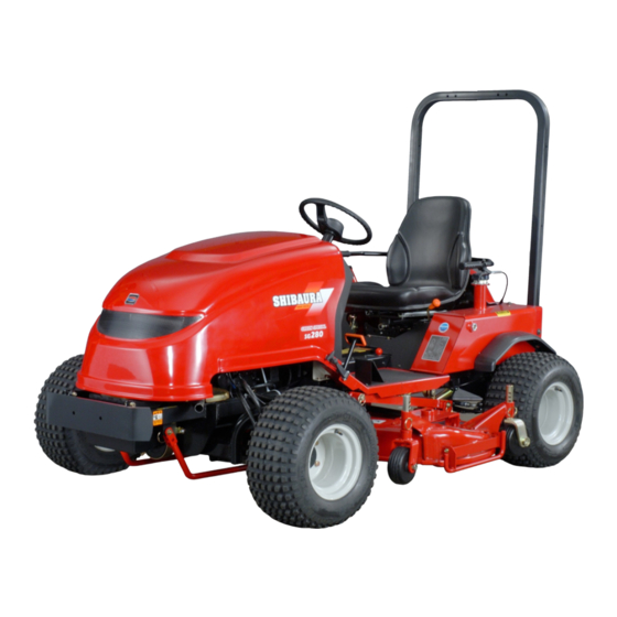
- Page 3 We have developed a riding slope mower that improves efficiency and reduces labor for work on sloped lawns. This manual describes the structure and functions of the SG280E, as well as its operation and troubleshooting measures, so that you can make the most of its capabilities.
-
Page 4: Table Of Contents
Contents Section 1 Overview ············································································································· 1-1 Specifications ············································································································· 1-2 Overall view [part names] ··························································································· 1-3 Maintenance precautions and procedures ································································· Section 2 Engine ················································································································· 2-1 Engine specifications ·································································································· 2-2 Cross-section diagrams ····························································································· 2-3 General precautions for disassembly/assembly ························································ 2-4 Disassembling the engine ·························································································· 2-5 Disassembling, inspecting, and assembling primary parts ········································... -
Page 5: Section 1 Overview
Section 1 Overview Specifications Overall view [part names] Maintenance precautions and procedures... - Page 6 Section 1 Overview 1-1 Specifications Model SG280E Total length (mm) 2495 Total width (mm) 1590 Total height (mm) 1900 (ROPS)/1200 (steering wheel) Wheelbase (mm) 1500 Front wheels (mm) 1310 Rear wheels (mm) 1310 Minimum ground clearance (mm) Reference: 140 (with mower deck in lowest position) Front wheel size 21x11.00-10...
- Page 7 1-2 Overall view [part names] Body and operation areas Fig.1-2-1 Fig.1-2-2...
- Page 8 Total elapsed time Fig.1-2-3 Seat swing lever...
-
Page 9: Maintenance Precautions And Procedures
Parking lever Fig.1-2-4 1-3 Maintenance precautions and procedures 1. Pre-maintenance precautions 1. Wash the mower clean, and then drain oil, fuel, coolant, and other fluids prior to disassembly as necessary. 2. Keep the maintenance workplace free from dust and brightly lit at all times. 3. - Page 11 Coarse thread Fine thread Screw * Strength dimen- Tightening torque Tightening torque Tightening torque Tightening torque Screw Screw division sions pitch (kgf⋅m) (N⋅m) pitch (kgf⋅m) (N⋅m) 3.80 to 4.80 37.2 to 47.0 4.40 to 5.60 43.1 to 54.9 1.75 6.70 to 8.50 65.7 to 83.3 1.25 7.60 to 9.60...
-
Page 12: Section 2 Engine
Section 2 Engine Engine specifications Cross-section diagrams General precautions for disassembly/assembly Disassembling the engine Disassembling, inspecting, and assembling primary parts Assembling the engine Electric components Troubleshooting Engine standard maintenance chart... -
Page 13: Engine Specifications
Section 2 Engine 2-1 Engine specifications N843 Type Water-cooled 4-cycle stand-alone diesel Cooling method Forced-circulation cooling Cylinder layout Vertical in-line Combustion Special excess flow type chamber type Number of cylinders Inner diameter x 84x90mm stroke Total stroke volume 1496cc Compaction ratio 22.2:1 Rated output 20.6kw (27.6HP)/2400rpm... -
Page 14: Cross-Section Diagrams
2-2 Cross-section diagrams Model N843 Fig.2-2-1... - Page 15 Model N843 Fig.2-2-2...
-
Page 16: General Precautions For Disassembly/Assembly
2-3 General precautions for disassembly/ assembly 1) During an overhaul Wear in cylinders, pistons, rings, and valves lead directly to the need for an engine overhaul. External indications of such wear take a variety of forms, making it difficult to make a certain judgment. Therefore, the best method is to perform inspections and maintenance on a regular basis, record the results, and then make a judgment based on that data. -
Page 17: Disassembling The Engine
2-4 Disassembling the engine 1. Removing the nozzle and glow plugs 1) Remove the high-pressure pipes * Clean to remove all debris before disassembly. 2) Remove the fuel return pipe 3) Remove the injection nozzle assembly 4) Remove the connector , and then remove the glow plugs . - Page 18 2) Remove the bypass hose and lower hose from the water pump 3) Remove the bolt , and then remove the water pump and gasket from the engine. 4) Remove the bolt , and then remove the plate the gasket from the water pump Fig.2-4-5 5.
- Page 19 8. Removing the tappet Pull the tappets up and out of the cylinder block. Fig.2-4-9 9. Removing the injection pump assembly 1) Remove the engine stop solenoid Fig.2-4-10 2) Remove the bolts and nuts holding the injection pump Fig.2-4-11 3) Slowly lift the injection pump over the stud bolts and then pull out the snap pin and remove it from the...
- Page 20 10. Removing the crank shaft pulley 1) Remove the lock nut , and then pull out the crank shaft pulley 2) Remove the key from the crank shaft Fig.2-4-13 11. Removing the timing gear case assembly Remove the bolts , and then remove the timing gear case Fig.2-4-14 12.
- Page 21 13. Removing the cam shaft assembly 1) Remove the anchor bolts from the plate * Remove one of the bolts after aligning it with the gear hole. [the hole indicated by the arrow in the figure on the right] 2) Pull the cam shaft out of the cylinder block.
- Page 22 2) Remove the anchor bolts from the bearing assembly holder on the crank shaft, and then slide the crank shaft off in the direction of the flywheel. Fig.2-4-21...
-
Page 23: Disassembling, Inspecting, And Assembling Primary Parts
2-5 Disassembling, inspecting, and assembling primary parts 1. Cylinder head 1) Use the valve spring replacer to compress the valve spring, and then remove the valve cotter , retainer , spring , and valve Fig.2-5-1 2) Remove the valve guide seal , if necessary. - Page 24 5) Inspect and check valves. Inspect the heads and stems of valves, and replace those with significant damage, wear, or deformation. Use a micrometer to measure valve stems at positions A, B, and C, and replace those that fall below the usage limit. Valve stem wear (mm) Intake valve Exhaust valve...
- Page 25 6) Inspect and check the valve spring. Visually examine the valve spring for damage. Squareness Measure the squareness of the spring. Replace the spring if the measurement exceeds the usage limit. Inspect the free length and spring force. Replace the spring if the measurement exceeds the usage limit.
- Page 26 3. Cylinder block 1) Inspect for cracks, damage, and deformation in the top Deformation in top of cylinder block (mm) of the block for each cylinder head. Assembly standard Required repair level 0.05 or less 0.12 or more 2) Visually inspect the internal diameter of the cylinder for scratches, rust, and corrosion.
- Page 27 3) Replace piston rings if they show signs of wear or damage. Insert the ring in the diameter of the skirt of the cylinder with the least wear, and then measure the clearance at the opening. Replace the piston ring if the value exceeds the usage limit. Fig.2-5-16 Engine model N843...
- Page 28 5) Measure the piston pin hole diameter and the piston pin external diameter. Replace the piston if the value exceeds the usage limit. Clearance between piston hole and piston pin (mm) Assembly standard Usage limit -0.00004 to +0.00043 0.02 or more Fig.2-5-18 5.
- Page 29 6. Connecting rod metal 1) Inspect the metal, and replace it if it shows Clearance between crank pin and connecting rod metal signs of peeling, melting, notching, or poor [oil clearance] (mm) contact. Assembly standard Usage limit 2) Use a plasti-gauge to measure the oil 0.035 to 0.085 0.2 or more clearance between the crank pin and the...
- Page 30 7. Bearing holders <<Center bearing>> 1) Remove the bearing holder, and replace the metal if Clearance between center journal and metal it shows signs of peeling, melting, notching, or poor (mm) contact. 2) Use a plasti-gauge to measure the oil clearance Assembly standard Usage limit Bearings No.
- Page 31 Assembling the bearing holder, center bearing, and thrust washer 1) Turn the stepped side of the bearing holder to the front (timing gear case side), and assemble so that the bearing holder with the cutting mark is in the center. 2) Assemble so that the bearing holder in which the thrust washer is inserted is located on the flywheel side.
- Page 32 9. Crankshaft 1) Support the crankshaft on a stand and apply a dial Crankshaft deflection (mm) gauge to the crankshaft journal to measure Assembly standard Required repair level deflection. If the measurement exceeds the required repair level, repair or replace the crankshaft. 0.02 or less 0.05 or more Fig.2-5-28...
- Page 33 3) Inspect the journal and cam for wear and damage. Replace them if their values exceed the usage limit. 4) Use an oil stone to repair damage to the small steps on the cam surface. A. Height of intake/exhaust valve cam (mm) Assembly standard Usage limit 34.45 to 35.01...
- Page 34 13. Nozzles and holders 1) Inspect the nozzle for burnout, clogging, and fuel Nozzle injection pressure Mpa (kgf/cm leakage on the seat surface. If the nozzle is defective, replace it. 15.19 to 16.17 (155 to 165) Fig.2-5-35 14. Flywheel and ring gear Inspect the ring gear for damage and significant wear.
-
Page 35: Assembling The Engine
2-6 Assembling the engine 1. Crankshaft and bearing holder assembly 1) Assemble the bearing holder on the crankshaft, and insert it into the bush on the front side of the cylinder block. 2) Align the bolt holes on the bottom of the cylinder block with the screw holes on the bearing holder during assembly. - Page 36 4. Piston and connecting rod 1) Apply engine oil to the metal surface, piston, and piston ring. 2) Turn the ring, power oil into the ring groove, and split the connection opening 90 degrees. 3) Use ring scissors to insert the connecting rods with the numerical marks facing toward the injection pump. CAUTION: Assemble the connection rods with the smallest numerical marks toward the front.
- Page 37 7. Cam shaft assembly and plate 1) Assemble the cam shaft assembly. 2) Fix the cam shaft assembly on the plate. Plate tightening torque N⋅m 8.8 to 12.7 (0.9 to 1.3 kgf⋅m) Fig.2-6-8 8. Idle gear and oil pump assembly 1) Assemble the thrust washer on the idle gear shaft.
- Page 38 9. Timing gear case 1) Install the start spring. While inserting the ring into the hole in the cylinder block, avoid damaging the oil seals as you assemble the case. Fig.2-6-12 10. Crankshaft pulley Insert the key into the crankshaft, and assemble the crankshaft pulley.
- Page 39 Adjusting injection timing After replacing the injection pump, cam shaft assembly, and cylinder block, use the following procedure to adjust the [SHPGRP] injection timing. 1) Insert a 0.5mm shim into the injection pump, and perform assembly according to the previous procedure. 2) Remove the delivery holder from the front side (radiator side) of the injection pump.
- Page 40 12. Oil filter and oil pipe 1) Apply oil to the filter installation surface, and tighten by hand. 2) Use an eye bolt to temporarily fix the cylinder block side only. CAUTION: After assembling the head, tighten the eye bolts on both sides.
- Page 41 4) Tighten the cylinder heads in the order shown in the figure on the right about 3 times before finally tightening to the rated torque. Cylinder head tightening torque N⋅m 98 to 102.9 (10 to 10.5 kgf⋅m) CAUTION: Apply molybdenum disulfide grease to the screws.
- Page 42 18. Water pump assembly Fig.2-6-25 19. Mano-contact (oil pressure switch) Mano-contact tightening torque N⋅m 9.8 to 11.76 (1.0 to 1.2 kgf⋅m) Fig.2-6-26 20. Nozzles and holder assembly Insert the gasket, and tighten to the rated torque. Nozzle and holder tightening torque N⋅m 58.8 to 68.6 (6.0 to 7.0 kgf⋅m) Fig.2-6-27 21.
-
Page 43: Electric Components
2-7 Electric components Repairs to electric components such as the alternator and starting motor must be performed at a factory specified by the manufacturer or by a qualified technician. 1. Alternator Specifications Model A007T03877 Mitsubishi Direction Right of rotation (when viewed from the pulley) Adjusting 14.5 to 15.0V voltage... - Page 44 2. Starting motor Specifications Model M001T66081 Mitsubishi Number of teeth on pinion gear Pinion gear Magnetic shift method shift method Fig.2-7-3 Parts list * Parts without a part code cannot be supplied. Part code Part name 185086551 Motor assembly 185846468 Bracket, front 185846615 Lever set...
- Page 45 3. Engine stop solenoid 1) Check if dimension A for the solenoid is from 25.5 to 26.4mm. If it is not within this range, replace the solenoid. Apply a voltage of 12V to the solenoid, and then check if dimension B is from 11.5 to 14.5mm. If it is not within this range, replace the solenoid.
-
Page 46: Troubleshooting
2-8 Troubleshooting Trouble Cause Solution Defective key switch Repair the connections and contacts. Insufficiently charged/discharged battery Charge the battery. No fuel Add fuel. Air in the fuel system Repair the area where there is air in the fuel. Clogged fuel filter Replace the fuel filter. -
Page 47: Engine Standard Maintenance Chart
2-9 Engine standard maintenance chart N843 Standard Maintenance chart * Numerical values for inspection items shown without units should be considered to be in units of mm. Required Standard Assembly Usage Inspection item repair Remarks dimension standard limit level Cylinder compression pressure 2.94(30) or 2.45(25) Engine 200rpm... - Page 48 Required Standard Assembly Usage Inspection item repair Remarks dimension standard limit level φ 67.951 Journal diameter φ φ 67.40 to 67.970 φ 51.964 Crank pin diameter φ φ 51.40 to 51.975 Journal and pin finishing 1.6Z precision 0.05 or Crankshaft deflection 0.02 or less more Allowance in crankshaft...
- Page 49 Required Standard Assembly Usage Inspection item repair Remarks dimension standard limit level Opening angle, before upper dead 13deg Intake center valve Closing angle, after lower dead 43deg center Opening angle, before lower dead 43deg Exhaust center valve Closing angle, after 13deg upper dead center Total length...
- Page 50 Required Standard Assembly Usage Inspection item repair Remarks dimension standard limit level Cooling method Forced circulation of coolant Coolant volume (liters) Thermostat start temperature, 80 to 84 degrees centigrade Thermostat fully open temperature, degrees centigrade Pump discharge rate (liters/min) Engine 2500rpm Water temperature: room temperature...
-
Page 51: Section 3 Hydraulic And Power Systems
Section 3 Hydraulic and Power Systems Hydraulic system diagram Functions Power system... -
Page 52: Hydraulic System Diagram
Section 3 Hydraulic and Power Systems 3-1 Hydraulic system diagram Overall circuit diagram Reverse Forward Fig.3-1-1... -
Page 53: Functions
3-2 Functions 1 1 1 1 . 走行系回路 走行系回路 走行系回路 走行系回路 走行部回路は、HST ユニット・前後輪走行モーター・2WD/4WD 切替バルブで構成されている。 2WD/4WD 切替バルブは、2WD 時はフロント駆動系のオイルを後輪モーターに合流させることにより、2倍の 油量で高速走行をさせている。また、4WD 時(作業時)は前輪、後輪モーターにオイルを分配させるように切替 する。 Fig.3-2-1... - Page 54 1) Oil flow during 2WD Fig.3-2-2 When the HST pedal is pressed forward, the oil fed to the HST variable pump flows together to the rear wheel motor after the oil circuit is changed via the 2WD/4WD valve. (red and light blue arrows in the diagram above) Therefore, since twice the volume of oil is sent to the rear wheel motor, the driving motor is operated at high speed and the sub-transmission shifts to "high".
- Page 55 2) Oil flow during 4WD Fig.3-2-3 When the HST pedal is pressed forward, the oil fed to the HST variable pump flows separately to the front and rear wheel motors after the oil is changed via the 2WD/4WD valve. (red and light blue arrows in the diagram above) Unlike the flow of oil during 2WD, the oil is supplied completely separately to the front and rear driving motors, and therefore the sub-transmission shifts to "low".
- Page 56 [Pressure setting: 5.39Mpa (55kfg/cm The SG280E uses a mechanical valve as the main valve for lifting and lowering the mower. Excess oil in the priority valve is returned to the tank, where it acts to also cool the rest of the oil.
- Page 57 This circuit is protected by a safety valve (relief valve) inside the steering unit that will open if the system is overloaded. The relief valve in the steering unit also functions to protect against overload in the lifting/lowering system. [Pressure setting: 5.39Mpa (55kfg/cm The SG280E uses a mechanical valve as the main valve for lifting and lowering the mower.
-
Page 58: Power System
3-3 Power system Mower drive system power flow Fig.3-2-6 Power is transmitted from the pulley installed on the engine flywheel to the pulley on the PTO shaft directly below, via a belt. This mower uses a tension method to engage/disengage power via belt tension, which is controlled smoothly by operating the mower clutch lever. -
Page 60: Section 4 Electric Components
Section 4 Electric Components Layout diagram Safety system, electric components... -
Page 61: Layout Diagram
Section 4 Electric Components 4-1 Layout diagram Fig.4-1-1 38951 0810 Battery () 55B24L 38541 0070 Fuse (5A) A4650 0171 Wire harness 38541 0200 Fuse (30A) 38565 0770 Battery cable: (+) 38541 0330 Slow blow fuse (50A) 38565 0930 Battery cable: (-) 38520 1260 HST neutral switch assembly A4620 0250... -
Page 62: Safety System, Electric Components
4-2 Safety system, electric components 1. Functions A safety circuit is provided for safe use of the system. The switches come ON when the driver sits on the seat, allowing electricity to flow to the engine and the engine to start. - Page 63 2. Layout and inspection procedures for electric components 1) Fuses (38541 0070/38541 0200) Inspect and replace damaged fuses. No. in Capacity Part code Related electric components diagram Safety relay, solenoid relay, seat timer, alternator 38541 0070 Pilot lamp, water temperature thermometer Electric components from external terminal 1 38541 0200 Electric components from external terminal 2, starter relay, alternator...
- Page 64 3) Relay (38523 0300), black (1) Layout and role of relay When electricity flows to the seat switch timer, the relay is triggered and the current flows. When the keys switch is in the START position, the relay is triggered and the current flows. When electricity flows to the safety start switch, the relay is triggered and the current flows to the glow plug.
- Page 65 (2) Inspection 1. Remove the timer from the mower, and connect the (+) terminal of a battery to terminal C. 2. Connect the cord with lamp for the tester to terminal A and the (+) terminal of the battery. 3. Connect terminal B to the (-) terminal on the battery, and confirm that the tester lamp flashes on and off normally at 1-second intervals.
- Page 66 (2) Inspection Refer to the operation circuit in the figure on the right to check for continuity between the marked areas. If there is no continuity, replace the switch. Fig.4-2-12 7) Brake safety switch (38520 1410) (1) Installation location and operation The brake switch is installed on the bottom right side of the step.
- Page 67 3. Check that there is continuity while the rod is pulled out of the switch. 4. If the above conditions are not met, replace the switch. Fig.4-2-15 8) PTO safety switch (A4620 0250) (1) Installation location and operation The PTO safety switch is installed beneath the mower clutch lever .
- Page 68 9) HST neutral switch (38520 1260) (1) Installation location and operation The switch is installed on the back of the frame. Electricity flows as long as the HST pedals is not pressed. If the driver accidentally steps on the pedal, the engine cannot be started. (2) Removing the switch 1.
- Page 69 Overheat Warning System Water TEMP Switch Temperature Switch Fig.4-2-24 Water temperature sensor (38572 0011) (1) Installation location and operation The water temperature sensor is installed on the engine thermostat case. The engine water temperature is always displayed water temperature thermometer on the panel. (2) Removing the switch 1.
-
Page 70: Section 5 Disassembling, Assembling, And Adjusting
Section 5 Disassembling, Assembling, and Adjusting Engine Power steering Driving motor Hydraulic hoses and pipes Front accelerator Control valve... -
Page 71: Engine
5-1 Engine 1) Removing the engine * Remove the mower in advance, if necessary. 1. Remove the battery cable , and then remove the battery 2. Separate the engine harnesses at the connectors. 3. Remove the bolts and nuts at the hinge on the bonnet, and then remove the bonnet Fig.5-1-1 4. - Page 72 8. Remove the accelerator wire from the governor lever * Carefully store the rubber and E clip to avoid losing them. 9. Remove the flexible shaft from the engine side. (cable for tachometer) Fig.5-1-5 10. Remove the belt covers (upper and lower ) on the PTO shaft drive, and then remove the V belt Fig.5-1-6...
- Page 73 13. Remove the bolts that fix the engine mount. (2 each on left and right sides) Fig.5-1-9 Fig.5-1-10 14. Connect a hoist line to the hangers (2 locations) on the engine, and use a chain block to lift out the engine assembly.
-
Page 74: Power Steering
Left, when viewed from the shaft Steering Type Full hydraulic (non-load reaction) Stroke (mm) Steering cylinder Inner diameter (φ) Regulated stream flow (liters/min) Relief valve Regulated pressure (Mpa) 5.88 Oil volume (liters) 23.0 Oil used Shibaura HST oil (ISO VG46) - Page 75 3. Power steering control valve 1) Structure and component parts Fig.5-2-2 No. in No. in Part No. Name Qty/unit Part No. Name Qty/unit diagram diagram 334011180 Steering case assembly Spring Control parts assembly O-ring Housing Relief adjust plug Sleeve Drive Spool O-ring Retaining link...
- Page 76 4. Hydraulic cylinder for power steering (34495 2711) 1) Structure and component parts No. in Part No. Name diagram 34495 2711 Cylinder assembly Cylinder tube sub-assembly Piston rod sub-assembly Guide 34496 0427 Piston 05231 0300 O-ring Rod packing Dust seal 34496 0429 Bush 05211 0290...
-
Page 77: Hst
5-3 HST 1. Specifications 2. Cross-section diagram PSV2-16AHG-1 Model A2101 0060 Number of input 1400 to 2600rpm revolutions Slope angle 0 to ±16deg 20.09∼21.07Mpa Max. working pressure (205 to 215 kgf/cm 0.098Mpa Internal case pressure (1 kgf/cm Piston pump 0 to 16.4 cm /rev Pumping Fig.5-3-1... - Page 78 2) Main HST unit (component parts list) Fig.5-3-3 Name Name Case Coupling Case Oil seal Port block Oil seal Cam plate O-ring Cylinder block O-ring Shaft O-ring Shaft O-ring Piston S/A O-ring Valve plate O-ring Valve plate Plug Thrust plate Retainer plate Snap ring Socket head bolt...
- Page 79 4. Operation 1) Operation principle < < < < < < < < Pump circuit> > > > > > > > The following figure shows the rotating area of a swash plate type axial piston pump. Nine pistons are built into the cylinder block.
- Page 80 2) Oil flow < < < < < < < < 1. Oil flow in neutral position> > > > > > > > The oil in neutral position flows as shown in the figure. Even if the input shaft rotates, the variable pump will not operate. Therefore, oil is not supplied from the pump to the drive motor.
- Page 81 < < < < < < < < 2. Oil flow when driving forward> > > > > > > > When the HST pedal is pressed forward, the variable pump operates and discharges oil. The high-pressure check valve is closed by hydraulic oil. The low-pressure side is opened by charge pressure. Although the check valve is open in the neutral position, as the circuit pressure increases while the mower is powered, the high-pressure valve port gradually closes.
- Page 82 < < < < < < < < 3. Oil flow when driving in reverse> > > > > > > > When the HST pedal is pressed backward, the variable pump operates and discharges oil. The oil flowing to the drive motor flows in the opposite direction as for forward driving.
- Page 83 3) Operation of valves inside the HST unit < < < < < < < < 1. Check/relief valve> > > > > > > > A combination valve that functions as both a balanced type high-pressure relief valve and a low-pressure supply check valve is used for both Valve body check &...
- Page 84 5. Measuring HST pressure < < < < < < < < High-pressure relief> > > > > > > > 1) Set the sub-transmission to H. 2) Tie the mower to a pillar or other structure to prevent it from driving away, and then press the forward pedal down to operate the relief valve while reading the needle on the pressure gauge.
- Page 85 < < < < < < < < 3. Adjusting stop distance> > > > > > > > The distance until stopping is adjusted by the strength Pedal Speed (km/h) of the spring . [Adjust the distance from full speed Forward 0 to 9 (4WD)/0 to 18 (2WD) with the sub-transmission in High until a complete stop...
-
Page 86: Driving Motor
5-4 Driving motor 1. Front wheel motor (A4002 0310) 1) Specifications 2) External view diagram Model ORB-S-205-3AT Discharge rate 205cm /rev Output torque 330N⋅m Fig.5-4-1 3) Repair parts layout diagram No. in Name diagram Needle bearing seal Backup ring X-ring O-ring Spring Steel ball... - Page 87 4) Disassembling and assembling the shaft seal Disassembly 1. Clamp the port in a vise, and remove the key. Fig.5-4-3 2. Remove the hexagonal bolts (M8). Fig.5-4-4 3. Remove the seal case from the main unit. CAUTION: 1. If the seal case is difficult to remove, use the bolts to turn it. (See the figure below.) 2.
- Page 88 4. Remove the square ring. Fig.5-4-8 5. Remove the O-ring, check spring, and steel ball. Fig.5-4-9 6. Use a precision driver to remove the dust seal. Fig.5-4-10 7. Use a precision driver to remove the X-ring. Fig.5-4-11...
- Page 89 8. Use a precision driver to remove the backup ring. CAUTION: Use #600 sandpaper to remove damage and scratches from each part. Wash each part, and blow dry with compressed air. Fig.5-4-12 Assembly 1. Insert the backup ring into the seal case. Fig.5-4-13 2.
- Page 90 3. Insert the dust seal into the seal case. CAUTION: Apply pressure to the dust seal. Fig.5-4-16 4. Assemble the drain check. Insert the steel ball, and apply grease to the spring. (Do this so that they will not fall out when the drain check is turned upside down.) Insert the O-ring.
- Page 91 6. Align the drain on the seal case with the drain on the main unit, and then place the seal case over the main unit. Fig.5-4-19 Fig.5-4-20 CAUTION: 1. Make sure that the steel ball does not fall out. 2. When installing together with the seal case, pay careful attention to the cut in the X-ring dust seal. 7.
- Page 92 2. Rear wheel motor 1) Specifications Model OMSB200 Flow rate 60 liters/min Continuous torque 470Nm 2) Cross-section diagram Fig.5-4-23 Intermediate plate Brake lock Fig.5-4-24...
- Page 93 3) Component parts (Since this is an originally designed motor, some parts might differ from the actual motor.) Fig.5-4-25 Name Name Hub cap Drain plug Split pin Washer Castle nut Intermediate plate Washer Cardin shaft Plug O-ring Brake drum Gear wheel set Wheel bolt Guide pin Brake shoe: A2810 0090...
- Page 94 4) Disassembly and assembly 1. Brakes 1. Brake drums 1) Remove the hub cap and split pin , and then remove the castle nut and washer 2) Use a puller to remove the brake drum Remove the key from the shaft. Fig.5-4-26 Fig.5-4-26 2.
- Page 95 2. Disk valve Remove the channel plate CAUTION: Make alignment marks before removing the disk valve. [Alignment mark for the disk valve and the channel plate [Alignment mark for the disk valve and the valve drive Fig.5-4-30 3. Valve drive Pull the valve drive out from the rotor.
- Page 96 6. Cardin shaft and intermediate plate 1) Pull out the Cardin shaft 2) Remove the intermediate plate Fig.5-4-34 CAUTION: 1. Pay careful attention to the orientation of the seal ring in the intermediate plate when replacing it. (See the figure on the right.) 2.
- Page 97 Assembly Perform assembly by following the disassembly procedure in reverse order. Use the rated torque when tightening screws (25). Screw (25) tightening torque 74.5 to 80.4N⋅ ⋅ ⋅ ⋅ m (7.6 to 8.2kgf-m) Castle nut (3) tightening torque 84.3N⋅ ⋅ ⋅ ⋅ m (8.6kgf-m) Fig.5-4-38...
-
Page 98: Hydraulic Hoses And Pipes
5-5 Hydraulic hoses and pipes Replace hoses and pipes that have become degraded, damaged, or worn. 1. Power steering and mower lift systems Fig.5-5-1 Part code Part name Remarks A4047 0440 Oil hose ; male seat G1/4 L=950 A4047 1170 Oil hose ;... - Page 99 2. Rear drive system Fig.5-5-2 Part code Part name Remarks A4047 1470 Oil hose ; male seat G1/2 L=445(P1) A4047 0800 Oil hose ; male seat G1/2 L=550(P2) A4047 0780 Oil hose ; male seat G1/2 L=400 A4047 0800 Oil hose ; male seat G1/2 L=440 A4047 0830...
- Page 100 3. Front drive system Fig.5-5-3 Part code Part name Remarks A4040 0620 Oil pipe A4040 0630 Oil pipe A4040 0600 Oil pipe A4040 0610 Oil pipe A4047 0850 Oil hose G3/8 L=650...
- Page 101 4. Oil pipe and hydraulic hose tightening torque Use the rated torque during assembly. Adapter w/washer lock nut tightening torque N⋅ ⋅ ⋅ ⋅ m (kgf⋅ ⋅ ⋅ ⋅ m) 39.2 49.0 58.8 Tightening torque (4.0) (5.0) (6.0) Locknut width (mm) High-pressure hose union nut tightening torque N⋅...
-
Page 102: Front Axle
5-6 Front axle 1. Front axle structure The center of the front axle is supported by a center pin method that is supported by the pivot shaft. The PTO shaft for the mower drive is built into the pivot shaft, for a structure in which power is transmitted from the engine to the mower. - Page 103 2. Removing the front axle * Remove the front link and universal joint on the mower before proceeding with this work. 1) Remove the battery cable (+, -), and then remove the battery 2) Remove the V belt that drives the PTO shaft. [Remove the upper and lower belt covers.]...
- Page 104 6) Remove the split pin from the tie rod, remove the , and then remove the tie rod assembly Fig.5-6-6 7) Lift the hydraulic motor with a hydraulic jack, and remove the snap ring and washer on the top of the king pin (motor bracket).
- Page 105 Needle bearing and bearings inside the pivot shaft 1) Replace the needle bearings if they show signs of wear or damage. CAUTION: During assembly, be aware that the one-side shield type needle bearing should be at the front. [The shield should face front.] When replacing the oil seal , pay careful attention to its orientation.
- Page 106 2) Tie rod lock nut tightening torque This is an important safety part. Use the rated torque when tightening. Tie rod lock nut tightening torque 131 to 163N⋅ ⋅ ⋅ ⋅ m (13.4 to 16.6kgf-m) Lock nut Fig.5-6-14 Front tire tightening torque and air pressure Front tire tightening Air pressure torque...
-
Page 107: Control Valves
5-7 Control valves 1. 2WD/4WD control valve 1) Specifications Part No. 34001 5632 Rated flow 65 liters/min Name Control valve Max. working pressure 24.5MPa (250kgf/cm 2) Structure and component parts Torque Forward Fig.5-7-1 No. in Part No. Name Qty/unit diagram 34001 5632 Control assembly 34029 3654... - Page 108 2. Main control valve 1) Specifications Part No. 34001 4770 Rated flow 15 liters/min Name Control valve Max. working pressure 6.9MPa (70kgf/cm 2) Structure Fig.5-7-2...
-
Page 109: Section 6 Wiring Diagram
Section 6 Wiring Diagram Wiring diagram... - Page 111 Fig.6-1-1...
Need help?
Do you have a question about the SG280E and is the answer not in the manual?
Questions and answers