Sign In
Upload
Manuals
Brands
Shibaura Manuals
Lawn Mower
ST321
Shibaura ST321 Manuals
Manuals and User Guides for Shibaura ST321. We have
3
Shibaura ST321 manuals available for free PDF download: Workshop Manual, Operator's Manual, Brochure & Specs
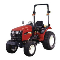
Shibaura ST321 Workshop Manual (248 pages)
Brand:
Shibaura
| Category:
Lawn Mower
| Size: 5.87 MB
Table of Contents
Introduction
2
Table of Contents
3
Index
3
Chapter 1 GENERAL
4
External Views
5
Specifications & Performances
6
Precautions before Servicing
8
Basic Understanding on Servicing
8
Metric Bolt Torque Specifications
9
Bolt Head Identification Mark
9
Sequence of Dismantling the Tractor
11
Manual Transmission Model
11
Hydrostatic Transmission Model
11
ENGINE and HST UNIT REMOVAL
12
Steering Wheel, Instrument Panel
12
Bonnet (Hood)
12
Battery
12
Air Cleaner Assembly
13
Radiator Assembly
13
Dash Board
13
Throttle Cable
13
Fuel Tank
14
Side Step
14
Suction Pipe
14
Diverter Valve
15
Rubber, Drive Shaft
15
Power Steering Piping
15
Wiring
15
HST Piping, Oil Cooler, Oil Filter with Base
16
Battery Base, Front Axle Support
16
Firewall
16
Power Steering Control Valve, Column
17
Engine
17
Clutch Housing
17
HST Unit
18
Damper, HST Shift Link Assembly
18
Transmission Removal
19
Front Side Cover
19
ROPS - Rear Wheel
19
Fender, Tool Box, Center Frame
20
Transmission Cover Plate
20
Shift Cover Assembly, Brake Rod
20
Suction, Return Tube
21
MID PTO and Rear PTO Change Lever Assembly
21
Range Gear Change Lever
22
Fwd Change Lever
22
Lift Cylinder Housing
22
Rear Axle Assembly
23
Installation and Trial Run
24
Return Spring
24
High Pressure Oil Pipe
24
O-Ring for HST
24
HST Cruise Control Rod
25
Front Axle Support Bolt
25
Steering Wheel Nut
26
Battery Cable
26
Trial Running
26
Chapter 2 ENGINE
28
Engine Sectional View
29
Engine Specifications
30
Disassembly, Inspections and Reassembly
31
Disassembly and Inspection of Engine Main Parts
35
Inspection and Service
35
Rocker Arm Ass’y
35
Wear of Rocker Arm Shaft
35
Cylinder Head Ass’y
36
Valve Guide and Valve Stem
36
Valve Head Thickness (MM)
36
Wear of Valve Stem (MM)
36
Clearance between Valve Stem and Valve Guide (MM)
37
Valve Seat
37
Valve Seat Contact Width (MM)
37
Valve Seat Recess (MM)
37
Inner Face of Combustion Chamber
38
Valve Spring
38
Cylinder Block
39
Measurement of Cylinder Bore
39
Clearance between Cylinder and Piston (MM)
40
Clearance between Piston Pin Hole and Piston Pin (MM)
40
Piston and Piston Ring
40
Piston Skirt Bottom Longer Dia. (MM)
40
Clearance between Piston Ring Groove and Ring (MM)
41
Piston Kit
41
Piston Ring
41
Piston Ring End Gap (MM)
41
Axial Play of Connecting Rod and Crank Pin (MM)
42
Clearance between Bush and Piston Pin (MM)
42
Connecting Rod
42
Torsion and Parallelism of Connecting Rod (MM)
42
Connecting Rod Metal
43
Center Bearing
44
Disassembly and Inspection
44
Of Bearing Holder
44
Crankshaft Bearing (Bush)
45
Crankshaft
46
Crankshaft Run-Out (MM)
46
Irregular Wear Limit of Crankshaft Journal and Pin (MM)
46
Cam Shaft Ass'y
47
Flywheel and Ring Gear
47
Timing Gear
47
Oil Flow
48
Oil Filter
49
Oil Pump
49
Removal from Engine
49
Water Pump Assembly and Thermostat
50
Radiator
51
Specifications and Structure
51
Fuel Filter
52
Fuel Passage
52
Governor
52
Nozzle and Holder
52
Injection Pump
53
Injection Condition
54
Air Cleaner
55
Cautions before Assembly
56
Engine Reassembly
56
Relief Valve Assembly with O-Ring
56
Fly Wheel
57
Piston and Connecting Rod Assembly
57
Rear Plate
57
Suction Pipe and Suction Filter
57
Front Plate
58
Oil Level Gauge and Gauge Guide
58
Oil Pan
58
Injection Pump Assembly
60
Injection Timing Adjustment
60
Engine Stop Solenoid
61
Tappet
61
Head Cover
63
Oil Pipe
63
Push Rod Rocker Arm Ass’y
63
Valve Clearance Adjustment
63
Glow Plug
64
Nozzle and Holder Ass’y
64
Oil Pressure Switch
64
Water Pump Ass’y
64
Exhaust Manifold
65
Electrical Units
66
Alternator
66
Brush Holder
67
Pulley
67
Rear End Cover
67
Bushing
68
Rectifier
68
Retainer Plate
68
Measurement on Vehicle
71
Regulated Voltage Check (IC Regulator)
71
Check for Alternator Output Current
72
Failure in Charging System
72
Preliminary Check
72
Care in Handling Charging System
74
Starting Motor
75
Operation and Function
75
Disassembly, Inspection and Reassembly
76
Armature
77
Commutator
77
Brush and Brush Holder
78
Continuity Test
78
Field Coil
78
Insulation Test
78
Bearing
79
Clutch
79
Magnetic Switch
79
Pinion Is Engaged, Motor Rotates, but the Engine Does Not Crank
80
Troubleshooting
80
Thermo Sensor
81
Glow Plug
81
Oil Pressure Switch
81
Specific Gravity of Electrolyte and Charging Condition
82
Battery
82
Engine Stop Solenoid
82
Fusible Link
83
Wiring Harness
83
Trouble Shooting
84
Engine Maintenance Standards Table
86
S753
86
S773L
94
Chapter 3. Tractor Main Body
98
Precautions before Start
99
Front Axle
100
Sectional Views
100
Reassembly of Front Axle
100
Wheel Drive
100
Case Cover
101
Front Wheel Support
101
Tie Rod Ass’y
101
Transmission Case
101
Arm (Knuckle) King Pin
102
Idler
102
King Pin
102
Wheel Shaft Case
102
Case Cover Ass’y
103
Differential Shaft
103
Drive Pinion
103
Final Pinion
103
Final Gear and Final Pinion
104
Transmission Case Ass’y
104
Casing
105
Runout of Front Wheel
105
Shaft Spline
105
Differential Ass’y
106
Backlash of Bevel Gear
107
Backlash of Bevel Gear (MM)
107
Reassembly of Drive Pinion
107
Wheel Alignment
108
Front Wheel
108
Swing Angle
108
Toe-In
108
Single Clutch
109
Drive Shaft
110
Clutch Disk COMPL
111
Release Bearing
111
Release Hub and Clutch Fork
111
Troubleshooting of Clutch
114
Manual Transmission
115
Change Lever Case
116
Disassembling Procedure
116
Top View
116
Counter Gear
118
Fixed Gear
118
4WD Drive Shaft
119
Main Shaft
119
Bearing Carrier
120
Counter Shaft
120
Gear Case (MID PTO)
122
MID PTO Counter Shaft
122
PTO Counter Shaft
122
Shifter Arms
123
Shifter Forks
123
Shifter Rod
123
MID PTO Shaft
124
MID PTO Shifter
124
Transmission for Range Shift
125
Clearance between Shifter Fork and Slide Gear
126
Differential
126
Backlash of Differential Gear and Differential Pinion
127
Heel Contact
127
Toe Contact
127
Tooth Contact of Drive Pinion and Ring Gear
127
Drive Pinion Ass’y (Drive Pinion and Ring Gear)
128
Oil Seals, O-Rings, and Gaskets.
128
Shifter
128
MID PTO Case
129
One-Way Clutch
129
PTO Shaft
129
Shift Airm·shift Guide
129
Bearing Retaining Plate
130
Thrust Washer
130
Hydrostatic Transmission
132
Disassembly of Hydrostatic Transmission
141
Drive Shaft (PTO)
141
Bearing Holder
142
Drive Shaft (Traveling)
142
Charge Pump Ass’y
155
Inspection and Reassembly of HST Unit
155
Piston Ass’y
155
Tightening Torque at each Part
156
Pressure
158
Check of Pressure of Low Pressure Relief Valve
159
Eye Bolt
159
Adjustment of Control Rod and Pedal Stop
160
Adjustment of HST Neutral
160
Link System
160
Change Lever Linkage
162
Main Shift Change Lever
162
Dimension Measurement from Outside
164
Disassembly, Inspection and Reassembly of Brake Ass’y
164
Real Axle and Brake
164
Specifications and Sectional View
164
Differential Lock Clutch
165
Differential Lock Fork
165
Differential Lock Pedal
165
Shift Arm
165
Final Gear
166
Wheel Shaft
166
Disk
167
Stator
167
Brake Adjustment
168
Brake Pedal Free-Play
168
Inspection of Tire
168
Rear Wheel
168
Adjustment of Wheel Track
169
Troubleshooting
169
Hand Brake
170
Steering and Linkage
173
External View
173
Specifications
173
Each Parts List
174
Power Steering Contorl Valve
174
Drive
175
Gear Pump
175
Relief Valve
175
Spool and Sleeve
175
Structure and Function of each Part
175
At Neutral
176
Left Turn
177
Right Turn
178
At Emergency (Engine Stop)
179
Disassembly and Reassembly of Control Valve
180
Power Steering Cylinder
186
Cylinder Head and Piston Rod
187
Cylinder Tube and Piston
187
Seal Components
187
Steering Pump
190
Troubleshooting (Steering Control Unit)
191
Hydraulic System
193
Name of Components (Hydraulic Circuit)
193
Specifications
193
Control Lever
195
Control Valve Ass’y
195
Of Cylinder Case Ass'y
195
Rod
195
Hydraulic Arm
196
Hydraulic Arm Shaft
196
Lift Arm
196
Piston
196
Cylinder Head
197
Control Valve
199
Name of Components
199
Operation (Flow of Oil)
200
When Valve Is at “O” Position
200
When Valve Is at “S” Position
200
Disassembly, Inspection and Reassembly of Control Valve
201
Relief Valve
201
Spool
201
Pressure Adjustment of Relief Valve
202
Control Valve (for Lifting/Lowering Implement) 34001611
203
Neutral Position
204
Lifting Position
205
Lowering Position
206
Linkage
207
“RAISE” Position
207
“LOWER” Position
208
Cap, Plate
209
Lever, Control Lever, Bracket
209
Poppet
209
Nut Tightening Torque
210
Pilot Spool
210
Spool Head Tightening Torque
210
Unload Valve, Check Valve
210
Installation of Poppet (Lowering Valve)
212
Adjustment of Feedback Link
213
Control Lever Return Rod Adjustment
213
Trouble Shooting
214
Remote Control Valve
216
Extending Position
218
Retracting Position
219
Electric Units and Accessories
221
Compornent Location
221
Instrument Panel Circuit
227
Wiring
227
Lighteing Circuit
228
Horn Circuit
229
Fuel Level Circuit
230
Engine Stop Solenoid Circuit
231
Engine Coolant Temperature Circuit, Engine Oil Pressure Warning Circuit
232
HST Cruise Control Circuit
233
Parking Brake Warning Light Circuit
234
Brake Lamp Circuit
235
Safety Start Circuit
236
Flasher and Hazard Lump Circuit
237
Glow Plug and Glow Lamp Circuit
238
Alternator and Engine Stop Solenoid Circuit
239
Cultivating Implement Installing Device
243
Three Point Link
243
Name of Major Components of Three-Point Link
243
Standard for Three-Point Link
243
PTO (Power Take-Off Shaft)
244
MID Mount PTO
244
Rear PTO
244
Maintenance Standards Table
245
Advertisement
Shibaura ST321 Operator's Manual (75 pages)
Brand:
Shibaura
| Category:
Tractor
| Size: 11.25 MB
Table of Contents
General Information
4
Table of Contents
5
Safety Precautions
6
Controls, Instruments and Operation
11
Seat, Seat Belt and Rops
11
Lighting
13
Starting the Engine
16
Stopping the Engine
17
Break-In Procedures
17
Throttle Controls
18
Brake Controls
19
Four-Wheel Drive
20
Mechanical Transmission
20
Hydrostatic Transmission
22
Clutch Pedal
23
Differential Control
23
Towing the Tractor
25
Hood Lutch
26
Three Point Linkage
26
Hydraulic Lift System
27
Driving the Tractor
32
Wheel Tread Settings
33
Tractor Weighting
34
Tire Pressures
36
Lubrication and Maintenance
37
Lubrication and Maintenance Chart
38
Fuel and Lubricants
38
Fuel and Lubricant Service Procedures
40
General Maintenance
46
Tractor Storage
60
International Symbols
75
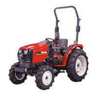
Shibaura ST321 Brochure & Specs (6 pages)
Compact Tractor
Brand:
Shibaura
| Category:
Lawn Mower
| Size: 1.33 MB
Advertisement
Advertisement
Related Products
Shibaura ST324
Shibaura ST329
Shibaura ST318
Shibaura ST333
Shibaura ST330
Shibaura ST440
Shibaura ST445
Shibaura SR525
Shibaura SX21
Shibaura SX24
Shibaura Categories
Lawn Mower
Controller
Tractor
Water Pump
Engine
More Shibaura Manuals
Login
Sign In
OR
Sign in with Facebook
Sign in with Google
Upload manual
Upload from disk
Upload from URL