Table of Contents
Advertisement
Quick Links
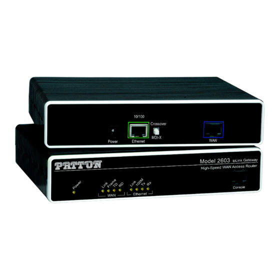
Models 2603, 2621, and 2635
OnSite Series High Speed Routers
User Manual
Important
This is a Class A device and is intended for use in a light industrial environment. It is
not intended nor approved for use in an industrial or residential environment.
Sales Office:
+1 (301) 975-1000
Technical Support:
+1 (301) 975-1007
E-mail:
support@patton.com
WWW:
www.patton.com
Document Number: 03328U1-001 Rev. D
Part Number: 07M2600Ser-GS
Revised: July 25, 2014
Advertisement
Table of Contents

Related Manuals for Patton 2603


Summary of Contents for Patton 2603
-
Page 1: User Manual
Models 2603, 2621, and 2635 OnSite Series High Speed Routers User Manual Important This is a Class A device and is intended for use in a light industrial environment. It is not intended nor approved for use in an industrial or residential environment. - Page 2 E-mail: Copyright © 2012–2014, Patton Electronics Company. All rights reserved. The information in this document is subject to change without notice. Patton Electronics assumes no liability for errors that may appear in this document. Warranty Information The software described in this document is furnished under a license and may be used or copied only in accordance with the terms of such license.
-
Page 3: Summary Table Of Contents
DHCP and DNS Configuration ........................80 IP Services ................................. 91 System Configuration ............................94 SNTP Client Configuration..........................103 System Status..............................107 Contacting Patton for assistance........................111 Compliance information ..........................114 Specifications ..............................116 Cable Recommendations ..........................120 OnSite Physical Connectors ..........................122 Command Line Interface (CLI) Operation ...................... -
Page 4: Table Of Contents
Overview............................25 Initial Configuration............................26 ............................27 Hardware Installation ............................27 What you will need ..........................27 Interface cable installation ............27 Installing an interface cable on the OnSite 2603’s T1/E1 interface port ............29 Installing an interface cable on the OnSite 2621’s X.21 interface port... - Page 5 Serial Interface ..............................43 Variables ........................44 Web Interface Configuration ........................44 T1/E1 Interface Configuration ................45 Configuring the OnSite Series 2603 for T1 Operation ..........................45 Web Configuration ................46 Configuring the OnSite Series 2603 for E1 Operation ..........................46 Web Configuration WAN Services ..............................48 ...............................49...
- Page 6 Models 2603, 2621, and 2635 User Manual Table of Contents .........................61 Remote Site Configuration ........................64 Central site configuration Security ................................66 ................................67 Introduction ............................68 Configuring the router Configuring the security interfaces.........................70 ..........................71 Configuring Security Policies ..........................72 Deleting a security Policy Enabling the Firewall.............................73...
- Page 7 111 ................................112 Introduction Contact information............................112 .......................112 Patton support headquarters in the USA ............112 Alternate Patton support for Europe, Middle East, and Africa (EMEA) Warranty Service and Returned Merchandise Authorizations (RMAs)..............112 ............................112 Warranty coverage ...........................113 Out-of-warranty service ............................113 Returns for credit ...........................113...
- Page 8 Models 2603, 2621, and 2635 User Manual Table of Contents ..............................117 T1/E1 Interface ..............................118 Protocol Support Support................................118 ...............................118 Management ................................119 Security .................................119 Dimensions Power and Power Supply Specifications.......................119 ........................119 AC universal power supply ..........................119 48 VDC power supply Cable Recommendations ..........................
-
Page 9: List Of Figures
Power connector location on rear panel (Model 2603/T shown) ........33 OnSite front panel LEDs and Console port locations (Model 2603 shown) ......34 Model 2603 home page . - Page 10 Models 2603, 2621, and 2635 User Manual New Policy link to configuration webpage ........... . 72 Deleting a Security Policy .
-
Page 11: List Of Tables
List of Tables General conventions ..............15 Status LED descriptions . -
Page 12: About This Guide
About this guide This guide describes installing and configuring Patton Electronics OnSite Series High Speed Routers. The instructions in this guide are based on the following assumptions: • The router may connect to a serial DTE device or T1/E1 line •... -
Page 13: Precautions
Models 2603, 2621, and 2635 User Manual Precautions Notes, cautions, and warnings, which have the following meanings, are used throughout this guide to help you become aware of potential problems. Warnings are intended to prevent safety hazards that could result in per- sonal injury. -
Page 14: Safety When Working With Electricity
Models 2603, 2621, and 2635 User Manual Safety when working with electricity • This device contains no user serviceable parts. The equipment shall be returned to Patton Electronics for repairs, or repaired by qualified service personnel. WARNING • Mains Voltage: Do not open the case the when the power cord is attached. -
Page 15: Factory Default Parameters
Model 2635 (V.35)—DB-25 port (DCE, DTE when using special V.35 cable) • Model 2603/T—T1 configuration. RJ-48C (100-ohm) interface • Model 2603/K—E1 configuration. RJ-48C (120-ohm) and dual-BNC interface (75-ohm) Typographical conventions used in this document This section describes the typographical conventions and terms used in this guide. General conventions The procedures described in this manual use the following text conventions: Table 1. -
Page 16: General Information
Chapter 1 General Information Chapter contents OnSite Series High Speed Routers overview ......................17 General attributes ............................17 Ethernet ................................18 Protocol support .............................18 PPP Support ..............................18 WAN Interfaces ..............................18 Management ..............................18 Security ................................19 Front Panel Status LEDs and Console Port .....................19 Console port .............................20 Rear panel connectors and switches .........................21... -
Page 17: Onsite Series High Speed Routers Overview
Ethernet port, MDI-X cross-over switch, console port, and internal or external power supply. There are three versions in the OnSite series corresponding to a choice of WAN interface: • The Model 2603 is equipped with an integrated T1/E1 CSU/DSU for connection to full and fractional T1/ E1 services. •... -
Page 18: Ethernet
Models 2603, 2621, and 2635 User Manual 1 • General Information Ethernet • Auto-sensing full-duplex 10Base-T/100Base-TX Ethernet. • Standard RJ-45 connector • Built-in MDI-X cross-over switch. • IEEE 802.1d transparent learning bridge • 2 IP address/subnets on Ethernet interface. Protocol support •... -
Page 19: Security
Models 2603, 2621, and 2635 User Manual 1 • General Information • Logging via SYSLOG, and VT-100 console. Console port set at 9600 bps 8/N/1 settings no flow control. Security • Packet filtering firewall for controlled access to and from LAN/WAN. Support for 255 rules in 32 filter sets. -
Page 20: Console Port
Models 2603, 2621, and 2635 User Manual 1 • General Information Table 2. Status LED descriptions Power Green ON indicates that power is applied. Off indicates that no power is applied. T1/E1 Link Green Solid green: connected Off: disconnected On: indicates a T1/E1 loss-of-frame condition. It also indicates that no T1/E1 signal is detected. -
Page 21: Rear Panel Connectors And Switches
Models 2603, 2621, and 2635 User Manual 1 • General Information Rear panel connectors and switches On the rear panel from left to right are the following: • Power input connector • Ethernet connector • MDI-X switch • WAN port (V.35, X.21, T1/E1) Power connector AC universal power supply. -
Page 22: Mdi-X
Models 2603, 2621, and 2635 User Manual 1 • General Information MDI-X The MDI-X push switch operates as follows: • When in the default “out” position, the Ethernet circuitry takes on a straight-through MDI configuration and functions as a transceiver. It will connect directly to a hub. -
Page 23: Product Overview
Chapter 2 Product Overview Chapter contents Introduction ................................24 Applications Overview............................25... -
Page 24: Introduction
The Serial port—Connects to local DTE devices (Model 2621 and 2635) • The T1/E1 port—Connects directly to T1/E1 lines (Model 2603) The router provides all layer 2 and layer 3 protocols required for end-to-end-link communication. When configuring the OnSite router, questions must be answered so the OnSite router functions as desired. -
Page 25: Applications Overview
Models 2603, 2621, and 2635 User Manual 2 • Product Overview Applications Overview Patton’s OnSite Gateway routers deliver all the advanced features for secure, reliable, and high speed Internet data connections. They combine ease-of-use with powerful data routing to make shared Internet connectivity simple and easy. -
Page 26: Initial Configuration
What you will need ............................27 Interface cable installation ..........................27 Installing an interface cable on the OnSite 2603’s T1/E1 interface port ............27 Installing an interface cable on the OnSite 2621’s X.21 interface port ............29 Installing an interface cable on the OnSite 2635’s V.35 interface port ............31... -
Page 27: Hardware Installation
“Installing an interface cable on the OnSite 2635’s V.35 interface port” on page 31) Installing an interface cable on the OnSite 2603’s T1/E1 interface port The OnSite Models 2603/K and 2603/T come with a selectable T1/E1 WAN interface (see figure 4). Located... -
Page 28: Rear View Of The 2603/T Showing Location Of Ethernet And Wan Connectors
WAN connector (RJ-45) (RJ-48C) / 1 0 I - X Figure 4. Rear View of the 2603/T showing location of Ethernet and WAN connectors RX RX TX TX 1 2 3 4 5 6 7 8 Figure 5. RJ-48C pin-out diagram... -
Page 29: Installing An Interface Cable On The Onsite 2621'S X.21 Interface Port
(RJ-45) (RJ-48C) / 1 0 I - X Figure 6. Rear view of the 2603/K showing location of Ethernet and WAN connectors The interface cable has been installed, go to section “Installing the AC power cord” on page 33. Installing an interface cable on the OnSite 2621’s X.21 interface port The OnSite Model 2621 comes with an X.21 interface presented on a female DB-15 connector (see... -
Page 30: Rear View Of The 2621 Showing Location Of Ethernet And X.21 Connectors
Models 2603, 2621, and 2635 User Manual 3 • Initial Configuration Ethernet connector X.21 Interface connector (RJ-45) (DB-15) 10/100 Crossover MDI-X Powe r Ethernet X .21 Interface / 1 0 I - X I n t f a c Figure 7. Rear view of the 2621 showing location of Ethernet and X.21 connectors When the local third party equipment is configured as DTE, the Model 3086 X.21 serial port can be config-... -
Page 31: Installing An Interface Cable On The Onsite 2635'S V.35 Interface Port
CAUTION mechanical serviceability. The Model 2635 V.35 (DB-25) interface is configured internally as a DCE. However, when using the Patton cable with the 2635, the V.35 interface at the M/34 end of the cable is a DTE (see figure 11). -
Page 32: Rear View Of The 2635 Showing Location Of Ethernet And V.35 Connectors
Models 2603, 2621, and 2635 User Manual 3 • Initial Configuration Ethernet connector V.35 Interface connector (RJ-45) (DB-25) 10/100 Crossover MDI-X Powe r Ethernet V.35 Interface / 1 0 I - X I n t f a c Figure 10. Rear view of the 2635 showing location of Ethernet and V.35 connectors Note The OnSite comes with a V.35 cable configured as a tail-circuit. -
Page 33: Installing The Ac Power Cord
AC power cord into the external power supply connector (see figure 12). 2. Insert the female end of the AC power cord into the internal power supply connector (see figure 12). Figure 12. Power connector location on rear panel (Model 2603/T shown) Hardware Installation... -
Page 34: Onsite Front Panel Leds And Console Port Locations (Model 2603 Shown)
WA N Ethernet Power WAN TD Ethernet Ethernet Tx Ethernet Rx Consol e Link LED port WAN Link WAN Frame Ethernet WAN RD 100M LED Figure 13. OnSite front panel LEDs and Console port locations (Model 2603 shown) Hardware Installation... -
Page 35: Installing The Ethernet Cable
Models 2603, 2621, and 2635 User Manual 3 • Initial Configuration Installing the Ethernet cable Do the following: The interconnecting cables shall be acceptable for external use and shall be rated for the proper application with respect to volt- age, current, anticipated temperature, flammability, and CAUTION mechanical serviceability. -
Page 36: Web Operation And Configuration
1. Launch a standard web browser such as Netscape Communicator or Internet Explorer (IE). 2. Enter the OnSite router’s IP address into the URL or Address field of the browser. To see the OnSite Series router home page, refer to the following Figures. Model 2603 is shown in figure... -
Page 37: Model 2621 Home Page
Models 2603, 2621, and 2635 User Manual 3 • Initial Configuration Figure 15. Model 2621 home page Figure 16. Model 2635 home page Hardware Installation... -
Page 38: Ethernet Lan Port
Chapter 4 Ethernet LAN Port Chapter contents Introduction ................................39 LAN Connections ............................39 Ethernet Port ..............................39... -
Page 39: Introduction
Models 2603, 2621, and 2635 User Manual 4 • Ethernet LAN Port Introduction The Ethernet LAN interface/port can be configured with two IP addresses, a primary and a secondary IP address. The configuration web page is found by following the path -> Services Configuration (in the Configu- ration Menu) ->... -
Page 40: Basic Ethernet Port Attributes
Models 2603, 2621, and 2635 User Manual 4 • Ethernet LAN Port Figure 18. Basic Ethernet port attributes For additional statistical parameters and a few configurable parameters, click on the hyperlink View advanced attributes... (See figure 19.) Figure 19. Advanced Ethernet port attributes The three configurable parameters are all either ‘true’... -
Page 41: Configurable Ethernet Parameters
Models 2603, 2621, and 2635 User Manual 4 • Ethernet LAN Port • Full Duplex Mode: the default value is ‘true’ for Full Duplex operation. Setting it to ‘false’ configures the Ethernet port to operate only in half-duplex mode. Rarely do these parameters require a change from their default operation. -
Page 42: Serial Port Configuration
..........................43 Serial Interface ..............................43 Variables ..............................43 Web Interface Configuration ........................44 T1/E1 Interface Configuration ........................44 Configuring the OnSite Series 2603 for T1 Operation ................45 Web Configuration ..........................45 Configuring the OnSite Series 2603 for E1 Operation ................46 Web Configuration ..........................46... -
Page 43: Wan Serial Port Configuration
The clock invert functions could be used to invert the clocks Clock Invert that are used on the serial interface. It is not recommended to change this parameter unless requested by Patton Elec- Normal tronics’ technical support. Keep at default. -
Page 44: Web Interface Configuration
50 for router/bridge and WAN service configuration. T1/E1 Interface Configuration The OnSite Series Model 2603 is equipped with a user selectable T1/E1 interface. The T1 interface is pre- sented on an RJ-48C (100-ohm) connector, while the E1 interface can use the RJ-48C (120-ohm) or dual BNC (75-ohm) connectors. -
Page 45: Configuring The Onsite Series 2603 For T1 Operation
Figure 23. Model 2603 T1/E1 WAN port configuration parameters Configuring the OnSite Series 2603 for T1 Operation Launch Netscape, Internet Explorer or similar web browser, type the IP address of the 2603, Web Configuration. enter username superuser and password superuser. From the main page click on the T1/E1 > Configuration. -
Page 46: Configuring The Onsite Series 2603 For E1 Operation
T1 network, set the unit for Receive Recover unless instructed otherwise by your service provider. Idle code: Enabled, Disabled. When enabled, the 2603 inserts idle codes (7E hex) on unused timeslots. Set this option to ‘Disabled’ unless instructed otherwise. - Page 47 FDL Mode: FDL is a T1 application, therefore select ‘Fdl- none’ for E1 applications. Clocking Mode: Options are Internal or Receive Recover Clock (network). In most applications clocking for the 2603 will be derived from the E1 network, set the unit for Receive Recover unless instructed otherwise by your service provider.
-
Page 48: Wan Services
Chapter 6 WAN Services Chapter contents WAN Services ...............................49 Configuring the OnSite Series 2603 for E1 Operation ................49 Web Configuration ..........................49 WAN Service Configuration..........................50 PPP Configuration ............................50 PPP Bridged ..............................50 PPP Bridged Remote Site Configuration ..................... 50 Central Site Configuration ........................ -
Page 49: Wan Services
FDL Mode: FDL is a T1 application, therefore select ‘Fdl- none’ for E1 applications. Clocking Mode: Options are Internal or Receive Recover Clock (network). In most applications clocking for the 2603 will be derived from the E1 network, set the unit for Receive Recover unless instructed otherwise by your service provider. -
Page 50: Wan Service Configuration
Models 2603, 2621, and 2635 User Manual 6 • WAN Services Configure and Activate Once all options have been selected, click on the button at the bottom of the screen. Additionally, save the configuration by going to the System Configuration > Save menu. -
Page 51: Central Site Configuration
Models 2603, 2621, and 2635 User Manual 6 • WAN Services Figure 28. WAN services’ options 4. In the Description field, enter the description you wish. This is a mandatory field. Without a description, you cannot create the WAN service. -
Page 52: Ppp Routed
Models 2603, 2621, and 2635 User Manual 6 • WAN Services 2. On the Menu, go to Services Configuration, then to WAN. Delete the factory default WAN services already defined. 3. Click on Create a new service in the main window, select PPP bridged and click on the Continue button. -
Page 53: Ppp Routed Configuration Menu
Models 2603, 2621, and 2635 User Manual 6 • WAN Services • Description: PPP Routed • Interface: 1 • WAN IP address: 192.168.164.2 255.255.255.255 • LLC Header Mode: off • HDLC Header Mode: ON • No authentication • Username: [blank] •... -
Page 54: Edit Ip Address Of Wan Port
Models 2603, 2621, and 2635 User Manual 6 • WAN Services Figure 31. Edit IP address of WAN port 7. Click on Services Configuration > IP Routes > Create new Ip V4 Route. Create the gateway to the remote router by entering the WAN IP address of the remote router, in this example, enter 192.168.164.3 in the Gateway field. -
Page 55: Central Site Configuration
Models 2603, 2621, and 2635 User Manual 6 • WAN Services Figure 33. PPP link status If the router at the ISP or Central site is another OnSite series, follow the instruc- Central Site Configuration. tions below. If not, consult your third party router user manual for configuration. -
Page 56: Lmi Management (Frame Relay Links)
Models 2603, 2621, and 2635 User Manual 6 • WAN Services Click on the Create button. 4. Go to Services Configuration > WAN > Edit... (for PPP routed) > Edit ‘IP Interface’ > Ipaddr: [enter the WAN IP Address and Mask, in this example = 192.168.164.3 and 255.255.255.255]. -
Page 57: Lmi Configuration Options
Models 2603, 2621, and 2635 User Manual 6 • WAN Services The Frame Relay Local Management Interface is configurable through either the LMI Configuration Options. CLI or web interface on the OnSite Series. The following variables are available for configuration. -
Page 58: Frame Relay Configuration
Models 2603, 2621, and 2635 User Manual 6 • WAN Services All LMI configuration variables are contained under the “LMI Management” window found through the Ser- vices Configuration >LMI Management link. The following screen shows the configuration variables available. Figure 34. LMI Configuration webpage Frame Relay Configuration The Frame Relay service can be configured for either bridged or routed applications. -
Page 59: Frame Relay Bridged
Models 2603, 2621, and 2635 User Manual 6 • WAN Services Frame Relay bridged This application shows configuration for two OnSite units in bridged mode. If using a third party router at the Central site, review the router’s configuration for connection to a remote bridge. -
Page 60: Central Site Configuration
Models 2603, 2621, and 2635 User Manual 6 • WAN Services • RX Max PDU: 8192 Receive side max PDU, default 8192 (normally not changed from default) • TX Max PDU: 8192 Transmit side max PDU, default 8192(normally not changed from default) •... -
Page 61: Frame Relay Routed
Models 2603, 2621, and 2635 User Manual 6 • WAN Services 5. Click on Create a new service in the main window, select Frame relay bridged and click on the Configure button. 6. Click along the following path: Services Configuration > WAN > ‘Edit...’ Then click on Edit ‘Frame Relay Channel’. -
Page 62: Frame Relay Routed Configuration
Models 2603, 2621, and 2635 User Manual 6 • WAN Services 4. Enter the description for the circuit in the Description field. This is a mandatory field. Without a descrip- tion you cannot create a WAN service. (See figure 38.) Figure 38. -
Page 63: Frame Relay Channel - Routed Configuration
Models 2603, 2621, and 2635 User Manual 6 • WAN Services Figure 39. Frame Relay Channel - Routed configuration Edit Frame Relay Channel Enter the appropriate information in the following fields: • Dlci: Consult with your service provider for the DLCI number required, in this example use 45. -
Page 64: Central Site Configuration
Models 2603, 2621, and 2635 User Manual 6 • WAN Services • Cost: 1 • Interface: frame-0 Figure 40. IP route for Frame Relay routed application 12. Click on the Update button. This concludes the configuration of the remote site. Be sure to save the configuration in non-volatile memory by System Configuration >... - Page 65 Models 2603, 2621, and 2635 User Manual 6 • WAN Services – Enable NAT on this interface. In this example leave this option blank 5. Click the Create button. 6. Go to System Configuration > WAN > Edit (for Frame Relay Routed service) > Edit ‘IP Interface’...
-
Page 66: Security
Chapter 7 Security Chapter contents Introduction ................................67 Configuring the router ............................68 Configuring the security interfaces.........................70 Configuring Security Policies ..........................71 Deleting a security Policy ..........................72 Enabling the Firewall.............................73 Firewall Portfilters ..............................73 Security Triggers..............................74 Intrusion Detection System (IDS) .........................75 Introduction to NAT ............................77 Enabling NAT ..............................77... -
Page 67: Introduction
Models 2603, 2621, and 2635 User Manual 7 • Security Introduction Security provides the ability to setup and enforce security policies. The policies define the types of traffic per- mitted to pass through a gateway, either inbound, outbound, or both, and from which origins the traffic may be allowed to enter. -
Page 68: Configuring The Router
Models 2603, 2621, and 2635 User Manual 7 • Security Configuring the router The configuration of security assumes that the OnSite router has been configured with a valid IP address for the Ethernet port so that the user may access the modem via the web page. If the IP address is still the factory default, go to the section in Chapter 3 entitled IP Address Modification. -
Page 69: Ip Address Of Ppp Routed Wan Service
Models 2603, 2621, and 2635 User Manual 7 • Security Figure 42. IP address of PPP routed WAN service The next step in configuring the router is to add the default gateway route. The WAN IP address of the routed PPP WAN service at the CO site is 192.168.101.2, so this will be the gateway IP address on the OnSite. -
Page 70: Configuring The Security Interfaces
Models 2603, 2621, and 2635 User Manual 7 • Security Configuring the security interfaces The interfaces and routes have been configured on the OnSite Router. The Ethernet side of the OnSite router will be configured to be an internal interface and the WAN side is selected to be the external interface since it is on “public”... -
Page 71: Configuring Security Policies
Models 2603, 2621, and 2635 User Manual 7 • Security Figure 45. Define ‘ip1’ interface as Internal 4. Again, click on the hyperlink Add interface... to define the WAN interface as “external.” 5. Select ‘ppp-0’ beside the Name pull-down menu, and select ‘external’ beside the Interface Type pull-down menu. -
Page 72: Deleting A Security Policy
Models 2603, 2621, and 2635 User Manual 7 • Security Figure 48. New Policy link to configuration webpage 3. Select the parameters so the policy is defined as follows: Between interfaces of types: external internal Validators will allow traffic. Click on Apply. -
Page 73: Enabling The Firewall
Models 2603, 2621, and 2635 User Manual 7 • Security Enabling the Firewall At this point, both security and the firewall can be enabled and the network is secure. All the interfaces which have been defined are protected, that is, all traffic has been blocked between the internal (‘ip1’) and external (‘ppp-0’) interfaces. -
Page 74: Security Triggers
Models 2603, 2621, and 2635 User Manual 7 • Security 2. Enter 1 (for ICMP) in the Protocol Number field. 3. Set both Inbound and Outbound for Allow. (See figure 50.) 4. Click on Create. Figure 50. Defining ICMP port filter for ping... -
Page 75: Intrusion Detection System (Ids)
Models 2603, 2621, and 2635 User Manual 7 • Security To enable the FTP data channel, add a trigger to open a secondary channel only when data is being passed. This minimizes the number of open ports. Each open port is a security risk. - Page 76 Models 2603, 2621, and 2635 User Manual 7 • Security Attack Name Protocol Attacking Host Blacklisted? WinNuke Xmas Tree Scan IMAP SYN/FIN Scan TCP Smurf ICMP If victim protection set SYN/FIN/RST Flood TCP If scanning threshold exceeded Net Bus Scan Back Orifice Scan 1.
-
Page 77: Introduction To Nat
Models 2603, 2621, and 2635 User Manual 7 • Security unacknowledged SYN/ACK packets. Once the queue is full, the system will ignore all incoming SYN request and no legitimate TCP connections can be established. – Once the maximum number of unfinished TCP handshaking sessions is reached, an attempted DOS attack is detected. -
Page 78: Global Address Pool And Reserved Map
Models 2603, 2621, and 2635 User Manual 7 • Security 1. Go to the “Security Interface Configuration” page by clicking on Security under Configuration in the menu. 2. Click on Enable NAT to internal interfaces in the Security Interfaces table. NAT is now enabled between the internal (LAN) and the external (WAN) interfaces of the firewall. -
Page 79: Nat Reserved Mapping Configuration
Models 2603, 2621, and 2635 User Manual 7 • Security Figure 54. NAT Reserved mapping configuration The PC on the Ethernet side of the OnSite can now communicate with the ‘public’ or ‘global’ side through NAT. Introduction to NAT... -
Page 80: Dhcp And Dns Configuration
Chapter 8 DHCP and DNS Configuration Chapter contents Introduction ................................81 Services and features normally associated with each other ................81 DHCP Server ..............................82 Parameters for the DHCP Server subnet ....................84 IP Addresses to be available on this subnet ....................85 DNS server option information .........................86 Default gateway option information ......................87... -
Page 81: Introduction
Models 2603, 2621, and 2635 User Manual 8 • DHCP and DNS Configuration Introduction The routers offer a DHCP Server, DHCP Relay capability, and DNS Relay incorporated into the OnSite. Of the two DHCP features, only one can be enabled at a time-either DHCP server or DHCP relay. -
Page 82: Dhcp Server
Models 2603, 2621, and 2635 User Manual 8 • DHCP and DNS Configuration Table 4. Features and services matrix The feature in this column [...] with (Column 1 feature) Configured Cannot be Must be used Usually used Can be used... -
Page 83: Dhcp Server Web Page
Models 2603, 2621, and 2635 User Manual 8 • DHCP and DNS Configuration Figure 55. DHCP Server web page The server needs to have a subnet of IP addresses which will be allocated when a DHCP client makes a request. -
Page 84: Parameters For The Dhcp Server Subnet
Models 2603, 2621, and 2635 User Manual 8 • DHCP and DNS Configuration Figure 56. DHCP server configuration web page Parameters for the DHCP Server subnet Four parameters are in the section for defining the DHCP subnet. (See figure 57.) Figure 57. -
Page 85: Ip Addresses To Be Available On This Subnet
Models 2603, 2621, and 2635 User Manual 8 • DHCP and DNS Configuration The third parameter is • Get subnet from IP interface: If you use this option, then you will not enter any values in the first two parameters. Should you define another subnet and also select ‘Get subnet from IP interface,’ the OnSite uses the ‘Get subnet from IP interface’... -
Page 86: Dns Server Option Information
Models 2603, 2621, and 2635 User Manual 8 • DHCP and DNS Configuration Figure 59. Example based on default range of IP address pool DNS server option information When a client requests an IP address from a DHCP server, the server can also send the IP addresses of the pri- mary and secondary DNS servers’... -
Page 87: Default Gateway Option Information
Models 2603, 2621, and 2635 User Manual 8 • DHCP and DNS Configuration Default gateway option information The OnSite is the gateway all client traffic when Use local host as default gateway is checked (see figure 61). Additional option information You may wish to provide additional information to the clients on the DHCP subnet. -
Page 88: Dhcp Relay Webpage
Models 2603, 2621, and 2635 User Manual 8 • DHCP and DNS Configuration • Edit DHCP server list: The IP addresses of DHCP servers can be updated, reset, or deleted from the list. • Add new DHCP server: the IP addresses of the DHCP servers are added to the DHCP relay list in this sec- tion. -
Page 89: Dns Relay
Models 2603, 2621, and 2635 User Manual 8 • DHCP and DNS Configuration Figure 63. DHCP Relay server list DNS Relay The DNS Relay webpage contains a configurable list of DNS server IP addresses. The OnSite device’s DNS Relay forwards DNS queries from a client to a pre-defined DNS server and DNS server responses to the client. -
Page 90: Dns Relay Configuration Webpage
Models 2603, 2621, and 2635 User Manual 8 • DHCP and DNS Configuration Figure 65. DNS Relay configuration webpage You can change the IP address of the DNS servers on the DNS Relay webpage (see figure 66) by modifying the IP address requiring the change and clicking on the Update button. -
Page 91: Ip Services
Chapter 9 IP Services Chapter contents IP Services ................................92 WEB Server ..............................92 CLI Configuration ............................92 Associated Ports for the different System (IP) Services ..................93... -
Page 92: Ip Services
Models 2603, 2621, and 2635 User Manual 9 • IP Services IP Services Certain System Services can be enabled or disabled. They are DNS Relay, FTP, TFTP, SNMP, and the WEB Server. The importance of disabling any of these services is an issue of security. If you are not using a particular service, it is best to disable it. -
Page 93: Associated Ports For The Different System (Ip) Services
Models 2603, 2621, and 2635 User Manual 9 • IP Services Associated Ports for the different System (IP) Services This section is for information purposes only. Consult the table to identify which ports are associated with the different System (IP) Services. -
Page 94: System Configuration
Chapter 10 System Configuration Chapter contents Introduction ................................95 Authentication...............................96 Alarm ..................................97 Remote Access ...............................98 Update ..................................98 Save ..................................99 Backup/Restore ..............................99 Restart .................................100 Website Settings ..............................100 Error Log................................101 SNMP Daemon ..............................101 System Tools ...............................102... -
Page 95: Introduction
Models 2603, 2621, and 2635 User Manual 10 • System Configuration Introduction The System Configuration item on the Configuration Menu opens to provide access to twelve (12) different items. They are: • Authentication: allows you to control access to the OnSite device’s console and web configuration pages. -
Page 96: Authentication
Models 2603, 2621, and 2635 User Manual 10 • System Configuration Authentication The OnSite manager controls access to the OnSite device’s console and web pages. The default defined user is superuser. See figure Figure 68. Authentication web page showing default superuser The superuser is the default administrative user and is given authority to configure the OnSite, but the default settings have disabled the ability to authenticate through a remote connection. -
Page 97: Alarm
Figure 70. Alarm Management web-page All OnSite devices have the ‘PP over Threshold’ and ‘NP over Threshold’ alarms. The Model 2603 has addi- tional alarms for the T1/E1 WAN port. An alarm can be tested by clicking on the Generate button. Similarly, by clicking on the Clear button, the alarm is cleared, that is, turned off, however the Time and Count parame- ters remain. -
Page 98: Remote Access
Models 2603, 2621, and 2635 User Manual 10 • System Configuration Figure 71. Alarm & Alarm Error Log configuration The Alarm Error Log can be enabled or disabled. The severity level of the Alarm Log can also be configured. Similarly each alarm can be set for its own severity level. -
Page 99: Save
Models 2603, 2621, and 2635 User Manual 10 • System Configuration Figure 73. Updating software Clicking on Options provides for selecting ‘Firmware Update Configuration.’ If enabled, the OnSite will pre- vent updating with incorrect software. Save To save configuration changes to non-volatile memory, it is essential to click on the Save button on this web- page. -
Page 100: Restart
Models 2603, 2621, and 2635 User Manual 10 • System Configuration Figure 75. Saving or reloading previously saved configuration files Restart From this webpage, you can do a soft reboot of the OnSite or restore the OnSite to factory defaults. To restore to factory defaults, click on the box for Reset to factory default settings. -
Page 101: Error Log
Models 2603, 2621, and 2635 User Manual 10 • System Configuration Error Log The Error Log webpage shows recent configuration errors and provides for the configuration of the Syslog. (See figure 78.) Two parameters are configurable for the Syslog. •... -
Page 102: System Tools
Models 2603, 2621, and 2635 User Manual 10 • System Configuration Figure 79. SNMP Daemon configuration The Trap Table identifies the IP address of the SNMP trap along with its password. System Tools The System Tools webpage provides two utilities for testing network connectivity. The two utilities are ‘ping’... -
Page 103: Sntp Client Configuration
Chapter 11 SNTP Client Configuration Chapter contents Introduction ................................104 Configuring the SNTP Client ..........................104 SNTP Client Mode Configuration Parameters .....................104 SNTP Client General Configuration Parameters ..................105 System Clock Setting............................105... -
Page 104: Introduction
Models 2603, 2621, and 2635 User Manual 11 • SNTP Client Configuration Introduction The Simple Network Time Protocol (SNTP) Client webpage contains the configurable parameters for either setting up the SNTP client or, in the absence of an SNTP server, setting the internal clock. -
Page 105: Sntp Client General Configuration Parameters
Models 2603, 2621, and 2635 User Manual 11 • SNTP Client Configuration SNTP Client General Configuration Parameters The general configuration parameters for the SNTP client are for selecting your timezone and setting the poll- ing parameters for the client’s transmit packets. - Page 106 Models 2603, 2621, and 2635 User Manual 11 • SNTP Client Configuration After entering the system clock values, click on the Set Clock button to save in volatile memory. If the OnSite is rebooted, either soft or by power-cycling, the Clock Setting returns to its default value.
-
Page 107: System Status
Chapter 12 System Status Chapter contents System Status...............................108 Port Connection Status ..........................108 LAN Status ..............................109 WAN Status ..............................109 Hardware Status ............................109 Defined Interfaces ............................109 Status LEDs.................................110... -
Page 108: System Status
Models 2603, 2621, and 2635 User Manual 12 • System Status System Status A quick but thorough summary of the OnSite device’s status is provided on this webpage, but it also has links to the detailed webpages for the key subsystems of the OnSite. -
Page 109: Lan Status
Models 2603, 2621, and 2635 User Manual 12 • System Status LAN Status There are two hyperlinks, LAN Settings... and DHCP Server Settings..., which go to the ‘LAN Connections’ and ‘DHCP Server’ webpages, respectively. The other parameters shown in LAN Status are as follows: •... -
Page 110: Status Leds
Models 2603, 2621, and 2635 User Manual 12 • System Status Status LEDs The LEDs indicate the status of the Power, the WAN, Sync Serial port, and the Ethernet connection. All LED indicators will present the same looking profile (e.g., clear) when unlit due to being single color, water clear, high efficiency LEDs. -
Page 111: Contacting Patton For Assistance
Contacting Patton for assistance Chapter contents Introduction ................................112 Contact information............................112 Patton support headquarters in the USA .......................112 Alternate Patton support for Europe, Middle East, and Africa (EMEA) ............112 Warranty Service and Returned Merchandise Authorizations (RMAs)..............112 Warranty coverage ............................112 Out-of-warranty service ...........................113 Returns for credit ............................113... -
Page 112: Introduction
RAS warranty and obtaining a return merchandise authorization (RMA). Contact information Patton Electronics offers a wide array of free technical services. If you have questions about any of our other products we recommend you begin your search for answers by using our technical knowledge base. Here, we have gathered together many of the more commonly asked questions and compiled them into a searchable database to help you quickly solve your problems. -
Page 113: Out-Of-Warranty Service
RMA#: xxxx 7622 Rickenbacker Dr. Gaithersburg, MD 20879-4773 USA Patton will ship the equipment back to you in the same manner you ship it to us. Patton will pay the return shipping costs. Warranty Service and Returned Merchandise Authorizations (RMAs) -
Page 114: Compliance Information
Compliance information Appendix A Chapter contents Compliance .................................115 ................................115 Safety ................................115 PSTN Regulatory ............................115 Radio and TV Interference (FCC Part 15) ......................115 CE Declaration of Conformity ..........................115 Authorized European Representative ........................115... -
Page 115: Compliance
Models 2603, 2621, and 2635 User Manual A • Compliance information Compliance • FCC Part 15, Class A • EN55022, Class A • EN55024 Safety • UL60950-1/CSA C22.2 No. 60950-1 • IEC/EN 60950-1 • AS/NZS 60950-1 PSTN Regulatory • These devices are not intended for connection to the PSTN. -
Page 116: Specifications
Appendix B Specifications Chapter contents General Characteristics ............................117 Ethernet ................................117 Sync Serial Interface ............................117 T1/E1 Interface ..............................117 Protocol Support ..............................118 Support................................118 Management ...............................118 Security ................................119 Dimensions .................................119 Power and Power Supply Specifications.......................119 AC universal power supply ........................119 48 VDC power supply ..........................119... -
Page 117: General Characteristics
Models 2603, 2621, and 2635 User Manual B • Specifications General Characteristics • Compact low-cost router/bridge • 10/100 Ethernet • Unlimited host support. • Comprehensive hardware diagnostics, works with any operating system, easy maintenance and effortless installation. • Built-in web configuration. -
Page 118: Protocol Support
Models 2603, 2621, and 2635 User Manual B • Specifications Protocol Support • Complete internetworking with IP (RFC 741), TCP (RFC 793), UDP (RFC 768), ICMP (RFC 950), ARP (RFC 826). • IP Router with RIP (RFC 1058), RIPv2 (RFC 2453), •... -
Page 119: Security
Models 2603, 2621, and 2635 User Manual B • Specifications Security • Packet filtering firewall for controlled access to and from LAN/WAN. Support for 255 rules in 32 filter sets. 16 individual connection profiles. • DoS Detection/protection. Intrusion detection, Logging of session, blocking and intrusion events and Real- Time alerts. -
Page 120: Cable Recommendations
Appendix C Cable Recommendations Chapter contents Ethernet Cable ..............................121 Adapter................................121... -
Page 121: Ethernet Cable
Models 2603, 2621, and 2635 User Manual C • Cable Recommendations Ethernet Cable Ethernet cable (P/N 10-2500) (refer to “RJ-45 shielded 10/100 Ethernet port” on page 123) The interconnecting cables shall be acceptable for external use and shall be rated for the proper application with respect to volt-... -
Page 122: D Onsite Physical Connectors
Appendix D OnSite Physical Connectors Chapter contents RJ-45 shielded 10/100 Ethernet port........................123 RJ-45 non-shielded RS-232 console port (EIA-561)....................123 Serial port................................123 V.35 (M/34 and DB-25 Connector) ......................123 X.21 (DB-15 Connector) ..........................124 E1/T1 (RJ-48C Connector) ..........................125... -
Page 123: Shielded 10/100 Ethernet Port
Models 2603, 2621, and 2635 User Manual D • OnSite Physical Connectors RJ-45 shielded 10/100 Ethernet port Assuming the MDI-X switch is in the out position. Table 7. Ethernet Port (MDI-X switch in out position) Pin No. Signal Name Direction... -
Page 124: Connector)
Models 2603, 2621, and 2635 User Manual D • OnSite Physical Connectors Table 9. V.35 pin-out for M/34 & DB-25 connectors M/34 DB-25 Signal Name Direction Pin No. Pin No. Frame/Chassis Ground TD-a from DTE RD-a to DTE from DTE... -
Page 125: E1/T1 (Rj-48C Connector)
Models 2603, 2621, and 2635 User Manual D • OnSite Physical Connectors Table 10. X.21 Interface (Model 2621) Pin No. Circuit Signal Name Direction Signal Timing-a to DTE DTE Common Return Transmit (Data)-a from DTE Control-b from DTE Receive (Data)-b... -
Page 126: T1/E1 Rj-48C Connector
Models 2603, 2621, and 2635 User Manual D • OnSite Physical Connectors RX RX TX TX 1 2 3 4 5 6 7 8 Figure 86. T1/E1 RJ-48C connector Serial port... -
Page 127: E Command Line Interface (Cli) Operation
Appendix E Command Line Interface (CLI) Operation Chapter contents Introduction ................................128 CLI Terminology ..............................128 Local (VT-100 emulation) ..........................128 Remote (Telnet) ............................128 Using the Console ............................128 Administering user accounts ..........................130 Adding new users ............................130 Setting user passwords ...........................130 Changing user settings ..........................131 Controlling login access ..........................131... -
Page 128: Introduction
Models 2603, 2621, and 2635 User Manual E • Command Line Interface (CLI) Operation Introduction The modem configuration and status can also be view and modified through the console, which is accessible through the RS-232 serial port or through a Telnet session over Ethernet. - Page 129 Models 2603, 2621, and 2635 User Manual E • Command Line Interface (CLI) Operation ethernet ?[After typing the “?” you will not see the “?”] add delete set show list clear ethernet Then you may enter one of the keywords on the displayed list followed by a space and “?”...
-
Page 130: Administering User Accounts
Models 2603, 2621, and 2635 User Manual E • Command Line Interface (CLI) Operation ip interface ip1 list secondaryipaddresses <enter> Secondary IP addresses for interface: ip1 IP Address -----|----------------- ----------------------- In this example there was not a secondary IP address. Now save the entire configuration in nonvolatile FLASH memory with the following command. -
Page 131: Changing User Settings
Models 2603, 2621, and 2635 User Manual E • Command Line Interface (CLI) Operation Enter new password: *** Again to verify: *** Note No check is made for any current password which may have been set for the user.
Need help?
Do you have a question about the 2603 and is the answer not in the manual?
Questions and answers