
Related Manuals for ACTi ACD-3100

Summary of Contents for ACTi ACD-3100
- Page 1 1-channel MPEG-4 Video Decoder ACD-3100 Ver. 090330 User’s Manual VoIPon www.voipon.co.uk sales@voipon.co.uk Tel: +44 (0)1245 808195 Fax: +44 (0)1245 808299...
-
Page 2: Precautions
PRECAUTIONS Read these instructions All the safety and operating instructions should be read before the product is operated. Heed all warnings All warnings on the product and in the instruction manual should be adhered to. The symbol indicates the following items, please carefully read the description next to each symbol. - Page 3 and can radiate radio frequency energy and, if not installed and used in accordance with the instruction manual, may cause harmful interference to radio communications. Operation of this equipment in a residential area is likely to cause harmful interference in which case the user will be required to correct the interference at his own expense.
-
Page 4: Table Of Contents
Table of Contents PRECAUTIONS__________________________________________________ ii Trademarks __________________________________________________________________ ii Liability _____________________________________________________________________ ii FCC/CE Regulation ____________________________________________________________ ii INSTALLATION _______________________________________________ 1-1 Package Contents _______________________________________________ 1-1 Features and benefits ____________________________________________ 1-2 Safety instructions _______________________________________________ 1-3 Physical description _____________________________________________ 1-5 Mounting the video decoder _______________________________________ 1-8 Basic connections________________________________________________ 1-9 VoIPon www.voipon.co.uk sales@voipon.co.uk Tel: +44 (0)1245 808195 Fax: +44 (0)1245 808299... -
Page 5: Installation
INSTALLATION 1.1 Package Contents ACD-3100 Warranty Card Software CD Terminal Blocks & Screws Power Adaptor (Option) VoIPon www.voipon.co.uk sales@voipon.co.uk Tel: +44 (0)1245 808195 Fax: +44 (0)1245 808299... -
Page 6: Features And Benefits
1.2 Features and benefits The video decoder is a high resolution, Ethernet (LAN and WAN) ready digital video decoder. Via an Ethernet network such as LAN or WAN, the video decoder takes a MPEG-4 stream from our IP camera or video server, and converts it in real-time with high quality analog video signals. -
Page 7: Safety Instructions
1.3 Safety instructions Don’t use the power supply with other voltages This device is likely to be damaged or damage other equipments / personnel, if you use a power supply with different voltage than the one included with this device. All warranty of this product will be voided in the situations above. - Page 8 If the video product does not operate normally by following the operating instructions in this manual. Adjust only those controls that are covered by the instruction manual as an improper adjustment . Other controls may result in damage and will often require extensive work by a qualified technician to restore the video product to its normal operation.
-
Page 9: Physical Description
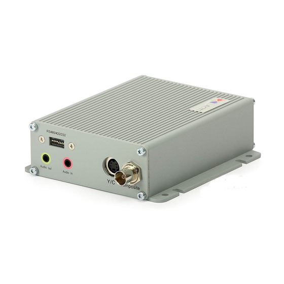
1.4 Physical description Action LED Indicator The LED will light up after IP device has successfully completed the boot process. Serial Port LED Indicator LEDs indicating when serial port is active. Reset Button Step 1: Switch off IP device by disconnecting the power cable Step 2: Using a suitable pointed object, press and continue to hold the Reset Button depressed. - Page 10 Digital Input 1 Digital Input 2 Ground Pin Terminal Blocks Pin 7~12 Pin 7~10: RS232/422/485. Default mode is RS-485 Pin 11~12: DC 12V power input DESCRIPTION NAME RS-485 RS-422 RS-232 Power Input (DC +12V) Ground Pin of Power Input & RS-232 Ethernet Port The IP device connects to the Ethernet via a standard RJ45 connector.
- Page 11 Audio Input / Output The IP device supports one audio input and output with earphone jack Y/C Output Analog Video Output of Y/C Signal with S-Video Connector 10. Composite Output Analog Video Output of Composite Signal with BNC Connector VoIPon www.voipon.co.uk sales@voipon.co.uk Tel: +44 (0)1245 808195 Fax: +44 (0)1245 808299...
-
Page 12: Mounting The Video Decoder
1.5 Mounting the video decoder The video decoder can be mounted onto a wall by using the accessories provided. VoIPon www.voipon.co.uk sales@voipon.co.uk Tel: +44 (0)1245 808195 Fax: +44 (0)1245 808299... -
Page 13: Basic Connections
1.6 Basic connections Follow the procedures below to connect the video decoder to the respective apparatuses. 1. The IP camera or other encoding devices as a video source 2. The video server or other encoding devices as a video source 3.
Need help?
Do you have a question about the ACD-3100 and is the answer not in the manual?
Questions and answers