H3C S3100-SI Series Quick Start Manual
Hide thumbs
Also See for S3100-SI Series:
- Operation manual (944 pages) ,
- Installation manual (85 pages)
Table of Contents
Advertisement
Quick Links
Download this manual
See also:
Operating Manual
Advertisement
Table of Contents

Subscribe to Our Youtube Channel
Related Manuals for H3C S3100-SI Series


Summary of Contents for H3C S3100-SI Series
-
Page 1: Quick Start
H3C S3100-SI Series Ethernet Switches Quick Start Hangzhou H3C Technologies Co., Ltd. http://www.h3c.com Manual Version: T2-08225G-20070415-C-1.05... - Page 2 Copyright © 2006-2007, Hangzhou H3C Technologies Co., Ltd. and its licensors All Rights Reserved No part of this manual may be reproduced or transmitted in any form or by any means without prior written consent of Hangzhou H3C Technologies Co., Ltd. Trademarks H3C,...
-
Page 3: About This Manual
About This Manual Related Documentation In addition to this manual, each H3C S3100-SI Series Ethernet Switches documentation set includes the following: Manual Content It is used for assisting the users H3C S3100-SI Series Ethernet in data configurations and Switches Operation Manual typical applications. - Page 4 Introduces the installation preparation and precaution of 2 Installation Preparation S3100-SI Series Ethernet Switches. Introduces the procedures to install an S3100-SI Series 3 Installation Ethernet Switch, including the setup of the mainframe, cards and cables. Introduces lightning protection 4 Lightning Protection of the...
- Page 5 Symbols Convention Description Means reader extremely careful. Improper operation may cause bodily Warning injury. Means reader careful. Improper operation may cause data loss or damage Caution to equipment. Note Means a complementary description. Environmental Protection This product has been designed to comply with the requirements on environmental protection.
-
Page 6: Table Of Contents
Quick Start H3C S3100-SI Series Ethernet Switches Table of Contents Table of Contents Chapter 1 Product Overview ............1-1 1.1 S3100-26T-SI Ethernet Switch ..........1-1 1.1.1 Appearance .............1-1 1.1.2 Front Panel ..............1-1 1.1.3 Rear Panel...............1-2 1.1.4 Power System ............1-3 1.1.5 Cooling System ............1-3 1.2 S3100-16T-SI Ethernet Switch ..........1-3... - Page 7 1.6.2 Front Panel ............1-13 1.6.3 Rear Panel.............1-14 1.6.4 Power System ............1-15 1.6.5 Cooling System .............1-16 1.7 S3100-SI Series Front Panel LEDs .........1-16 1.7.1 Power LED ............1-16 1.7.2 Mode LEDs and Port Status LEDs ......1-16 1.7.3 MODE button............1-17 1.8 S3100-SI Series Technical Specifications .......1-18 1.8.1 S3100-26T-SI/S3100-16T-SI/S3100-8T-SI Ethernet...
- Page 8 Quick Start H3C S3100-SI Series Ethernet Switches Table of Contents Chapter 3 Installation ..............3-1 3.1 Installation of the Switch ............3-1 3.1.1 Mounting the Switch into a 19-Inch Cabinet....3-1 3.1.2 Mounting the Switch on a Workbench.....3-3 3.1.3 Wall-Mount ..............3-3 3.2 Installation of Expand Card..........3-5 3.3 Connection of Power Cord and Grounding Wire ....3-6...
-
Page 9: Chapter 1 Product Overview
Quick Start H3C S3100-SI Series Ethernet Switches Chapter 1 Product Overview Chapter 1 Product Overview 1.1 S3100-26T-SI Ethernet Switch 1.1.1 Appearance As shown in the following figure, the S3100-26T-SI Ethernet Switch provides 10/100Base-TX Ethernet ports, 10/100/1000Base-T Ethernet ports, and one Console port. -
Page 10: Rear Panel
Quick Start H3C S3100-SI Series Ethernet Switches Chapt er 1 Product Overvie (1) Power LED (2) A/L mode LED (3) D/S mode LED (4) Port left LED (yellow) (5) Port right LED (green) (6) 10/100 Base-TX port (7) 10/100/1000 Base-T port... -
Page 11: Power System
Rated voltage range: 100 VAC to 240 VAC, 50/60 Hz Max voltage range: 90 VAC to 264 VAC, 47 Hz to 63 Hz 1.1.5 Cooling System The S3100-SI Series Ethernet Switches (hereinafter referred to as S3100-SI series) cool off in nature way. 1.2 S3100-16T-SI Ethernet Switch 1.2.1 Appearance... -
Page 12: Rear Panel
Quick Start H3C S3100-SI Series Ethernet Switches Chapt er 1 Product Overvie (1) Power LED (2) A/L mode LED (3) D/S mode LED (4) Port left LED (yellow) (5) Port right LED (green) (6) 10/100 Base-TX port (7) 10/100/1000 Base-T port... -
Page 13: Power System
Rated voltage range: 100 VAC to 240 VAC, 50/60 Hz Max voltage range: 90 VAC to 264 VAC, 47 Hz to 63 Hz 1.2.5 Cooling System The S3100-SI series cool off in nature way. 1.3 S3100-8T-SI Ethernet Switch 1.3.1 Appearance... -
Page 14: Rear Panel
Quick Start H3C S3100-SI Series Ethernet Switches Chapt er 1 Product Overvie (1) Power LED (2) A/L mode LED (3) D/S mode LED (4) Port left LED (yellow) (5) Port right LED (green) (6) 10/100 Base-TX port (7) 10/100/1000 Base-T port... -
Page 15: Power System
Rated voltage range: 100 VAC to 240 VAC, 50/60 Hz Max voltage range: 90 VAC to 264 VAC, 47 Hz to 63 Hz 1.3.5 Cooling System The S3100-SI series cool off in nature way. 1.4 S3100-26C-SI/S3100-26C-SI-DC Ethernet Switch 1.4.1 Appearance... -
Page 16: Rear Panel
Quick Start H3C S3100-SI Series Ethernet Switches Chapter 1 Product Overvie (1) Power LED (2) A/L mode LED (3) D/S mode LED (4) Port left LED (yellow) (5) Port right LED (green) (6) 10/100 BASE-TX port (7) Expansion slot (8) Console port... -
Page 17: Power System
Quick Start H3C S3100-SI Series Ethernet Switches Chapter 1 Product Overview I. Rear panel of the S3100-26C-SI model supporting AC input: (1) AC power socket (2) Grounding screw Figure 1-12 Rear panel of the S3100-26C-SI model supporting AC input II. Rear panel of the S3100-26C-SI model supporting DC... -
Page 18: S3100-16C-Si/S3100-16C-Si-Dc Ethernet Switch
Quick Start H3C S3100-SI Series Ethernet Switches Chapter 1 Product Overview Max voltage range: –36 VDC to –72 VDC 1.4.5 Cooling System The S3100-SI series cool off in nature way. 1.5 S3100-16C-SI/S3100-16C-SI-DC Ethernet Switch 1.5.1 Appearance shown following figure, S3100-16C-SI/S3100-16C-SI-DC Ethernet Switch provides 16 x 10/100Base-TX Ethernet ports, two expansion slots, and one Console port. -
Page 19: Rear Panel
Quick Start H3C S3100-SI Series Ethernet Switches Chapt er 1 Product Overvie (1) Power LED (2) A/L mode LED (3) D/S mode LED (4) Port left LED (yellow) (5) Port right LED (green) (6) 10/100 BASE-TX port (7) Expansion slot... -
Page 20: Power System
Quick Start H3C S3100-SI Series Ethernet Switches Chapter 1 Product Overview I. Rear panel of the S3100-16C-SI model supporting AC input: (1) AC power socket (2) Grounding screw Figure 1-16 Rear panel of the S3100-16C-SI model supporting AC input II. Rear panel of the S3100-16C-SI model supporting DC... -
Page 21: Cooling System
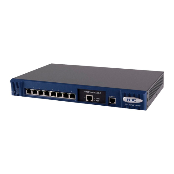
Quick Start H3C S3100-SI Series Ethernet Switches Chapter 1 Product Overview 1.5.5 Cooling System The S3100-SI series cool off in nature way. 1.6 S3100-8C-SI/S3100-8C-SI-DC Ethernet Switch 1.6.1 Appearance As shown in the following figure, the S3100-8C-SI/S3100-8C-SI -DC Ethernet Switch provides 8 x 10/100Base-TX Ethernet ports, one expansion slot, and one Console port. -
Page 22: Rear Panel
Quick Start H3C S3100-SI Series Ethernet Switches Chapt er 1 Product Overvie (1) Power LED (2) A/L mode LED (3) D/S mode LED (4) Port left LED (yellow) (5) Port right LED (green) (6) 10/100 BASE-TX port (7) Expansion slot... -
Page 23: Power System
Quick Start H3C S3100-SI Series Ethernet Switches Chapter 1 Product Overview I. Rear panel of the S3100-8C-SI model supporting AC input: (1) AC power socket (2) Grounding screw Figure 1-20 Rear panel of the S3100-8C-SI model supporting AC input II. Rear panel of the S3100-8C-SI model supporting DC input:... -
Page 24: Cooling System
Chapter 1 Product Overview 1.6.5 Cooling System The S3100-SI series cool off in nature way. 1.7 S3100-SI Series Front Panel LEDs 1.7.1 Power LED Table 1-1 Description of the power LED on S3100-SI series Mark on the panel Status Description The switch is powered on. -
Page 25: Mode Button
Quick Start H3C S3100-SI Series Ethernet Switches Chapter 1 Product Overview Table 1-2 Description of the port status LEDs on the S3100-SI series Mode LED Port status LEDs and Description status their status Data is passing through Flashing the port. -
Page 26: S3100-Si Series Technical Specifications
Quick Start H3C S3100-SI Series Ethernet Switches Chapter 1 Product Overview After the switch is powered on, the A/L LED lights up initially. If you press the MODE button, the D/S LED lights up. After that, if you press the MODE button again within 45 seconds, the A/L LED lights up again, or else the A/L LED automatically lights up after 45 seconds. - Page 27 Quick Start H3C S3100-SI Series Ethernet Switches Chapter 1 Product Overview S3100-26T- Item S3100-16T-SI S3100-8T-SI 24 x 16 x 10/100Base- 10/100Base-T 10/100Base- auto-sensing auto-sensing auto-sensing Number of fixed ports ports ports ports 10/100/1000 10/100/1000B 10/100/1000 Base-T ports ase-T port Base-T port...
-
Page 28: S3100-26C-Si/S3100-16C-Si/S3100-8C-Si Ethernet Switch Technical Specifications
Quick Start H3C S3100-SI Series Ethernet Switches Chapter 1 Product Overview 1.8.2 S3100-26C-SI/S3100-16C-SI/S3100-8C-SI Ethernet Switch Technical Specifications Table 1-4 S3100-26C-SI/S3100-16C-SI/S3100-8C-SI Ethernet Switch technical specifications Item S3100-26C-SI S3100-16C-SI S3100-8C-SI Physical 42 x 436 x 240 42 x 436 x 200 42 x 326 x 200 dimension mm (1.7 x 17.2... - Page 29 Quick Start H3C S3100-SI Series Ethernet Switches Chapter 1 Product Overview Item S3100-26C-SI S3100-16C-SI S3100-8C-SI 10/100/1000BASE-T interface module with max transmission distance of 100 m (328.1 feet) 100BASE-SX (SC, 2 km (1.2 mi)) 100BASE-LX (SC, 15 km (9.3 mi)) 100BASE-LH40 (SC, 40 km (24.9 mi)) 1000BASE-SX (SC, 0.5 km (0.3 mi))
- Page 30 Quick Start H3C S3100-SI Series Ethernet Switches Chapter 1 Product Overview Item S3100-26C-SI S3100-16C-SI S3100-8C-SI PoE (as powered Not supported Supported Supported device) System power 20 W 12 W 10 W consumption (full load) None None None Operating 0°C to 45°C...
-
Page 31: Chapter 2 Installation Preparation
Quick Start Chapter 2 Installation H3C S3100-SI Series Ethernet Switches Preparation Chapter 2 Installation Preparation 2.1 Precautions To avoid any device impairment and bodily injury because of improper use, please take the following precautions: Before cleaning the switch, pull out the power plug of the switch. -
Page 32: Requirements On Environment
H3C S3100-SI Series Ethernet Switches Preparation 2.2 Requirements on Environment S3100-SI series must be used indoors. When you install your switch in a cabinet or install it directly on a workbench, you must ensure: Enough space is left near the air-intake hole and the ventilation hole of the switch for the heat dissipation of the switch chassis. -
Page 33: Cleanness Requirements
Quick Start Chapter 2 Installation H3C S3100-SI Series Ethernet Switches Preparation damage to the switch. High temperature for a long time will speed up the aging of insulation material, greatly lower the reliability of the switch and greatly reduce the life span of the switch. -
Page 34: Anti-Interference Requirements
Quick Start Chapter 2 Installation H3C S3100-SI Series Ethernet Switches Preparation Table 2-2 Limits on harmful gas in the equipment room Max content (mg/m³) 0.006 0.05 0.01 2.2.3 Anti-interference Requirements A switch in use may be affected by the interference from outside... -
Page 35: Laser Usage Security
2.2.4 Laser Usage Security S3100-SI series are category-1 laser equipment. When an optional optical interface card of the S3100-SI series is operating, it is prohibited to stare into the optical interface because the laser beam emitted from the optical fiber takes high energy and may hurt your retina. -
Page 36: Chapter 3 Installation
Chapter 3 Installation Caution: On a mounting screw of the chassis of any H3C Series Switches, there is a seal which must be kept intact before the agent maintains the switch for you. You must get the permission of your local agent before you can open the chassis. - Page 37 Quick Start H3C S3100-SI Series Ethernet Switches Chapter 3 Installation Step 2: Place the switch on a shelf of the cabinet, and slide the switch into the cabinet along the guides in the cabinet to an appropriate position. Step 3: Insert screws through the mount ears into the front mounting posts of the cabinet and tighten them, ensuring the switch is fixed steadily in the cabinet.
-
Page 38: Mounting The Switch On A Workbench
A clearance of about 10 cm is reserved around the switch for heat dissipation. No heavy object is placed on the switch. The S3100-SI series are designed with no fan. Therefore, you should install them in a drafty environment, and keep at least 1.5 cm vertical distances between the neighboring devices if you need to stack the switches one upon another. - Page 39 Quick Start H3C S3100-SI Series Ethernet Switches Chapt er 3 Installation Figure 3-3 Anchor kit illustration The wall-mount procedure is as follows (see Figure 3-4): Drill two holes in the wall on the same horizontal line, with a distance of 169 mm.
-
Page 40: Installation Of Expand Card
Quick Start H3C S3100-SI Series Ethernet Switches Chapter 3 Installation Caution: When mounting the switch, keep the Ethernet ports of the switch facing downwards and the two sides with ventilation holes vertical to the ground. 3.2 Installation of Expand Card Note: The following section describes the procedures to install an ONU card. -
Page 41: Connection Of Power Cord And Grounding Wire
Quick Start H3C S3100-SI Series Ethernet Switches Chapter 3 Installation II. Installation of an ONU subcard Step 1: Dismount the dummy panel of an expansion slot of the switch. Step 2: Insert the ONU card into the expansion slot to the place. -
Page 42: Connecting Dc Power Cord
Quick Start H3C S3100-SI Series Ethernet Switches Chapter 3 Installation II. Connecting AC power cord Step 1: Connect one end of the chassis grounding wire (coming with the switch) to the grounding screw on the rear of the chassis and the other end to the ground nearby. - Page 43 Quick Start H3C S3100-SI Series Ethernet Switches Chapter 3 Installation Step 1: Connect one end of the chassis grounding wire (coming with the switch) to the grounding screw on the rear of the chassis and the other end to the ground nearby.
-
Page 44: Connecting Grounding Wire
Quick Start H3C S3100-SI Series Ethernet Switches Chapter 3 Installation 3.3.3 Connecting Grounding wire Caution: You should properly connect the switch grounding wire since it is crucial to the lightning protection and electromagnetic shield (EMS) of your switch. The power input end of the switch is connected with a noise filter, whose central ground is directly connected to the chassis, forming the so-called chassis ground (commonly known as PGND). - Page 45 Quick Start H3C S3100-SI Series Ethernet Switches Chapter 3 Installation ( 2 ) ( 2 ) ( 3 ) ( 3 ) ( 3 ) ( 3 ) ( 1 ) ( 1 ) ( 1 ) ( 1 )
- Page 46 Quick Start H3C S3100-SI Series Ethernet Switches Chapter 3 Installation Figure 3-9 Grounding the switch by burying the grounding bod into the earth For an AC-powered switch, if none of the above two conditions is available, ground it through the PE wire of the AC power supply.
- Page 47 Quick Start H3C S3100-SI Series Ethernet Switches Chapt er 3 Installation ( 1 ) ( 1 ) ( 1 ) ( 1 ) (11 ) (11 ) (11 ) (11 ) ( 2 ) ( 2 ) ( 2 )
-
Page 48: Connecting Optical Fiber
Quick Start H3C S3100-SI Series Ethernet Switches Chapter 3 Installation 3.4 Connecting Optical Fiber Caution: After a switch starts, the PON interface may emit invisible radial when there is no optical connector connected to it and the protective cap is removed from it. Therefore, do not stare into the optical interface. -
Page 49: Connection Of Console Cable
Quick Start H3C S3100-SI Series Ethernet Switches Chapter 3 Installation Step 3: Plug the optical connector into the PON interface of the ONU subcard. 3.5 Connection of Console Cable 3.5.1 Console Cable Console cable is an 8-core shielded cable. At one end of the cable is a crimped RJ45 connector to be connected to the Console port of the switch;... -
Page 50: Connecting Console Cable
Quick Start H3C S3100-SI Series Ethernet Switches Chapter 3 Installation RJ-45 Signal Direction DB-9 → → 3.5.2 Connecting Console Cable Follow these steps to connect a terminal device, a PC for example, to the switch: Step 1: Connect the DB-9 female connector of the Console cable to the serial port of the PC or the terminal device used to configure the switch. -
Page 51: Installation Verification
Quick Start H3C S3100-SI Series Ethernet Switches Chapter 3 Installation Note: When connecting a PC to a powered-on switch, you are recommended to connect the DB-9 connector of the Console cable to the PC before connecting the RJ45 connector to the switch. When... -
Page 52: Chapter 4 Lightning Protection Of The Switch
Quick Start Chapter 4 Lightning Protection H3C S3100-SI Series Ethernet Switches of the Switch Chapter 4 Lightning Protection of the Switch 4.1 Installation of Lightning Arrester for AC Power (Socket Strip with Lightning Protection) Caution: Lightning arrester will not be shipped with the switch. You should purchase it by yourself if needed. - Page 53 Quick Start Chapter 4 Lightning Protection H3C S3100-SI Series Ethernet Switches of the Switch G rounding and polarity indicator (red) : O n m eans that the lines are w rongly connected (either the ground w ire is not w ell connected, or the live and zero lines are w rongly connected).
- Page 54 Quick Start Chapter 4 Lightning Protection H3C S3100-SI Series Ethernet Switches of the Switch Caution: Make sure that the arrester is well grounded before using the lightning arrester for power. After inserting AC power cord plug of switch into the socket of...
-
Page 55: Installation Of Lightning Arrester For Network Port
Quick Start Chapter 4 Lightning Protection H3C S3100-SI Series Ethernet Switches of the Switch 4.2 Installation of Lightning Arrester for Network Port Note: Lightning arrester for network port is specially designed for the Ethernet port of 10/100M electrical interface (RJ-45 connector is adopted in this case). - Page 56 Quick Start Chapter 4 Lightning Protection H3C S3100-SI Series Ethernet Switches of the Switch II. Installation procedure Step 1: Tear the protection paper at one side of the double faced adhesive tape apart from the tape, and stick the tape on the surface of the arrester.
- Page 57 Quick Start Chapter 4 Lightning Protection H3C S3100-SI Series Ethernet Switches of the Switch Network cable indoors Network cable led i nto from outdoor Lightning arrester f or network port Switch (attached onto th e chassis) Ground wire of light...
- Page 58 Quick Start Chapter 4 Lightning Protection H3C S3100-SI Series Ethernet Switches of the Switch interconnect with other devices via cables outdoor, you should install lig htning arresters for all these network ports for protection.
Need help?
Do you have a question about the S3100-SI Series and is the answer not in the manual?
Questions and answers