Table of Contents
Advertisement
Advertisement
Table of Contents
Troubleshooting

Subscribe to Our Youtube Channel
Related Manuals for DFI 586ITBD


Summary of Contents for DFI 586ITBD
- Page 1 586ITBD Rev. A+ System Board User’ s Manual 34270620...
- Page 2 Copyright This publication contains the information that is protected by copyright. No part of it may be reproduced in any form or by any means or used to make any transformation/adaptation without the prior written permission from the copyright holders. This publication is provided for informational purposes only.
- Page 3 FCC and DOC Statement on Class B This equipment has been tested and found to comply with the limits for a Class B digital device, pursuant to Part 15 of the FCC rules. These limits are designed to provide reasonable protection against harmful interference when the equipment is operated in a residential installation.
-
Page 4: Table Of Contents
Table of Contents Chapter 1 - Introduction Features and Specifications................Package Checklist....................Chapter 2 - Hardware Installation Preparing the Area....................Handling the System Board................Installing the System Board................Board Layout......................System Memory..................... Cache Memory....................... Processor Upgrade Information..............Jumper Settings for Intel Processors........... Jumper Settings for Cyrix/IBM Processors........ - Page 5 IDE HDD Auto Detection................HDD Low Level Format.................. Save & Exit Setup....................Exit Without Saving..................... Chapter 4 - Driver Installation ® Pre-installation Guide to Windows 95........... ® Installing IDE Drivers for Windows 95..........Appendix A - DIM and SIM Modules Types of Modules....................
- Page 6 586ITBD System Board User’ s Manual CHAPTER Introduction...
-
Page 7: Features And Specifications
• Intel 82430TX PCIset chipset System Memory The 586ITBD supports 8MB to 256MB of memory. It is equipped with two DIMM and four SIMM sockets. The 168-pin DIMM sockets use x64 EDO (60/70ns), fast page mode (60/70ns), or SDRAM (10/ 12/13ns), 3.3V. - Page 8 RTC Timer to Power On the System The RTC installed on the 586ITBD system board allows your system to automatically wake up on the set day and time. Set the day and time you would like your system to power on in the “...
- Page 9 - The chassis or cabinet has poor ventilation. • Monitors 5V and 12V power voltages and failure alarm. The 586ITBD is able to detect the output voltage of your power supply. If the output voltage is over or under 5V or 12V (±10%), an alarm will sound warning you of voltage irregularity.
-
Page 10: Usb Ports
• One 20-pin ATX power supply connector • One 12-pin standard AT power supply connector USB Ports The 586ITBD is equipped with two connectors for external USB ports. USB allows data exchange between your computer and a wide range of simultaneously accessible external Plug and Play... -
Page 11: Expansion Slots
16-bit ISA slots and 1 shared PCI/ISA slot. All PCI and ISA slots are bus masters. Power Supply Connectors The 586ITBD is a Baby AT form factor system board designed to fit into an ATX form factor chassis. The board is equipped with both ATX and AT power supply connectors. -
Page 12: Package Checklist
586ITBD System Board User’ s Manual Package Checklist The 586ITBD package contains the following items: • The 586ITBD system board • The 586ITBD user’ s manual • Serial, mouse and printer port cables Option 1: One card-edge bracket with a 9-pin and 25-pin serial port... -
Page 13: Chapter 2 - Hardware Installation
CHAPTER Hardware Installation... -
Page 14: Preparing The Area
586ITBD System Board User’ s Manual This chapter summarizes the steps to install the 586ITBD system board into your system unit. It also includes a description of the area in which you must work and directions for memory installation. Before installing the system board, obtain the memory you plan to install. -
Page 15: Hardware Installation
ESD protection. Installing the System Board If you are installing the 586ITBD system board, the following outlines the basic installation steps. Before installing the system board into your system unit, you should prepare the tools you will need. - Page 16 Install the processor. Be sure pin 1 of the processor is aligned with pin 1 of the socket. Set the corresponding jumpers. 10. Install the prepared 586ITBD system board into the case and replace the screws. 11. Reinstall all cards and connectors and replace the system unit...
-
Page 17: Board Layout
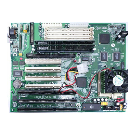
Hardware Installation Board Layout square denotes pin 1... -
Page 18: System Memory
Note: DIM and SIM modules cannot exist on the 586ITBD system board at the same time. Use either SIMM or DIMM only. DIMM The two 168-pin DIMM (Dual In-line Memory Module) sockets use x64 EDO, FPM and SDRAM. -
Page 19: Installing The Dim Module
Hardware Installation DIM 1 Memory Size DIM 0 16MB 16MB none 16MB 16MB 24MB 24MB 16MB 32MB none 32MB 32MB 32MB none 32MB 16MB 16MB 40MB 32MB 40MB 32MB 48MB 16MB 32MB 48MB 32MB 16MB 32MB 64MB 32MB Installing the DIM Module A DIM module simply snaps into a socket on the system board. - Page 20 586ITBD System Board User’ s Manual SIMM The SIM sockets are divided into two banks on the system board, Bank 0 and Bank 1. Each bank consists of 2 SIMM sockets. Your system board supports 8MB to 256MB of memory using...
- Page 21 Hardware Installation The following table summarizes the bank locations and modules needed for the corresponding memory sizes. Bank 0 Bank 1 Memory Size — — — — — 16MB — — 16MB — 16MB 24MB 24MB 16MB — 32MB 16MB —...
- Page 22 586ITBD System Board User’ s Manual Bank 0 Bank 1 Memory Size 64MB 136MB 64MB 64MB 136MB 64MB 64MB 144MB 64MB 64MB 64MB 144MB 160MB 16MB 16MB 64MB 64MB 160MB 64MB 64MB 16MB 16MB 32MB 64MB 192MB 32MB 64MB 64MB...
-
Page 23: Cache Memory
Hardware Installation Cache Memory The 586ITBD system board supports 512KB pipeline burst, direct map write-back cache installed at locations U8 and U9 of the sys- tem board. One SRAM is mounted on location U10 for tag SRAM to store the cacheable addresses. Refer to page 17 for the locations of the SRAMs and tag SRAM. -
Page 24: Jumper Settings For Intel Processors
586ITBD System Board User’ s Manual Jumper Settings for Intel Processors Processors-Ext. Bus Clk J P 1 J P 3 J P 8 JP10 JP11 J P 4 3-4 On 3-4 On All Off 1-2 On 1-2 On 5-6, 7-8 On... -
Page 25: Jumper Settings For Cyrix/Ibm Processors
Hardware Installation Jumper Settings for Cyrix/IBM Processors Processors-Ext. Bus CLK J P 1 J P 3 J P 8 JP10 JP11 J P 4 PR150+ - 60MHz 3-4 On 3-4 On All Off 1-2 On 2-3 On 1-2, 3-4 On PR166+ - 66MHz 3-4 On 3-4 Off... -
Page 26: Jumper Settings For Amd Processors
586ITBD System Board User’ s Manual Jumper Settings for AMD Processors Processors-Ext. Bus CLK J P 1 J P 3 J P 8 JP10 JP11 J P 4 K5 PR90 - 60MHz 3-4 On 3-4 On All Off 1-2 On... -
Page 27: Installing Upgrade Processors
Hardware Installation Installing Upgrade Processors The 586ITBD is equipped with a 321-pin Zero Insertion Force (ZIF) socket at location U11 of the system board. Refer to page 17 for the location of the ZIF socket. This socket is designed for easy removal of an old processor and easy insertion of an upgrade processor. - Page 28 586ITBD System Board User’ s Manual To install an upgrade processor, do the following: 1. Make sure the handle on the side of the ZIF socket is up. To raise the handle, push it down, slightly pull it out to the side, then raise it as far as it will go.
- Page 29 Hardware Installation 3. Position the processor above the ZIF socket. Make sure pin 1 of the processor is aligned with pin 1 of the socket. Lower the processor until the pins are inserted properly in their corresponding holes. Remember that very little force is needed to install the processor.
- Page 30 586ITBD System Board User’ s Manual Installing A Fan/Heatsink Position the fan/heatsink on the processor such that the air from the side of the fan/heatsink will flow across the heat regulators on the system board. See the figure below. Clearance Requirements Your processor comes with a heatsink mounted on top.
-
Page 31: Jumper Settings For Cmos Clear
Normal (default) Jumper Settings for Modem Ring-on Jumper JP2 Modem Ring-on Select The 586ITBD supports the Modem Ring-on feature which allows the Soft Power Down (Soft-Off) PC to power on to respond to incoming calls. With an external modem installed, you can... -
Page 32: Factory Testing Jumpers
586ITBD System Board User’ s Manual 1. Set JP2 according to the COM port where your modem is connected. 2. If your ATX power supply has an On/Off switch, set this to On so that even when you have shut down (“ soft power off” ) your system, it will always remain in “... -
Page 33: Ports And Connectors
Hardware Installation Ports and Connectors The 586ITBD system board comes with two serial ports, one paral- lel printer port, one shrouded floppy disk header, two shrouded IDE hard disk headers, two connectors for external USB ports, one IrDA connector, a PS/2 mouse port, a PS/2 or AT keyboard port, a fan connector, one AT power supply connector and one ATX power supply connector. -
Page 34: Parallel Port
Mouse Clock Reserved Parallel Port The 586ITBD system board has a standard printer port for interfac- ing your PC to a parallel printer. It supports SPP, ECP and EPP modes. You can set the port’ s mode in the Integrated Peripherals setup of the Award BIOS. -
Page 35: Floppy Disk Drive Controller
Floppy Disk Drive Controller The 586ITBD system board is equipped with a shrouded floppy disk header that supports two standard floppy disk drives. You can install any 360KB, 720KB, 1.2MB, 1.44MB, or 2.88MB floppy disk drives. - Page 36 The end-most connector should be attached to the drive you want to designate as Drive A. IDE Hard Disk Interface The 586ITBD system board is equipped with two shrouded PCI IDE headers that will interface four Enhanced IDE (Integrated Drive Electronics) hard disk drives.
- Page 37 We recommend that you use Enhanced IDE or ATA-2 and ATA-3 hard drives be from the same manufacturer. In a few cases, drives from two different manufacturers will not function properly when used together. The problem lies in the hard drives, not the 586ITBD system board.
- Page 38 586ITBD System Board User’ s Manual Important: If you encountered problems while using an ATAPI CD-ROM drive that is set in Master mode, please set the CD-ROM drive to Slave mode. Some ATAPI CD-ROMs may not be recognized and cannot be used if incorrectly set in Master mode.
- Page 39 Hardware Installation Universal Serial Bus Ports The 586ITBD system board is equipped with two connectors, at locations J9 and J10 on the system board, for external USB ports. USB allows data exchange between your computer and a wide range of simultaneously accessible external Plug and Play peripherals.
-
Page 40: Irda Connector
USB cable connector USB port cables (optional) IrDA Connector The 586ITBD system board is equipped with an IrDA connector for wireless connectivity between your computer and peripheral de- vices. Connect your IrDA cable to connector J24 on the system board. Make sure “ Onboard IR Controller” in the Integrated Periph- erals setup of the Award BIOS is Enabled. -
Page 41: Cpu Fan Connector
Function +12V Power Supply Connectors The 586ITBD is a Baby AT form factor system board designed to fit into an ATX form factor chassis. The board is equipped with both ATX (J11) and AT (J1) power supply connectors. “ Power-Supply Type” in the Chipset Features Setup must be set according to the type of power supply installed in your computer. - Page 42 586ITBD System Board User’ s Manual With an external modem installed, you can power on your system to remotely transmit or access data. Refer to Chapter 3 - “ Resume By Ring” in the Power Management Setup of the Award BIOS to enable this function, and Chapter 2 - Jumper Settings for Modem Ring-on.
- Page 43 Hardware Installation J28 (LEDs and Switches) Pin 1 ATX LED LED Power Pin 2 (ATX power LED) Ground Pin 1 HDD LED LED Power Pin 2 (Primary/Secondary IDE LED) Si g nal Pin 1 GR LED LED Power Pin 2 (Green LED) Si g nal Pin 1...
-
Page 44: Expansion Slots
586ITBD System Board User’ s Manual Expansion Slots The 586ITBD system board is equipped with 3 dedicated PCI slots, 2 dedicated 16-bit ISA slots and 1 shared PCI/ISA slot. All PCI and ISA slots are bus masters. -
Page 45: Chapter 3 - Award Bios Setup Utility
CHAPTER Award BIOS Setup Utility... -
Page 46: The Basic Input/Output System
586ITBD System Board User’ s Manual The Basic Input/Output System The Basic Input/Output System (BIOS) is a program that takes care of the basic level of communication between the processor and peripherals. In addition, the BIOS also contain codes for various advanced features found in this system board. -
Page 47: Award Bios Setup Utility
Award BIOS Setup Utility ROM PCI/ISA BIOS STANDARD CMOS SETUP AWARD SOFTWARE, INC. Date (mm:dd:yy) : Mon, Jul 29 1996 Time (hh:mm:ss) : 13: 27: 50 HARD DISKS TYPE SIZE CYLS HEAD PRECOMP LANDZ SECTOR MODE Primary Master Auto Auto Primary Slave Auto Auto... - Page 48 586ITBD System Board User’ s Manual You can use Type “ User” to define your own drive type manually. This information should be included in the documentation from your hard disk vendor. If the controller of the HDD interface is ESDI, you must select “ Type 1”...
- Page 49 Award BIOS Setup Utility Halt On This category determines whether the system will stop if an error is detected during power up. The default setting is All Errors (BIOS default, Setup default). No Errors The system boot will not stop for any errors detected. All Errors The system boot will stop whenever the BIOS detects a non-fatal error.
-
Page 50: Bios Features Setup
586ITBD System Board User’ s Manual BIOS Features Setup The BIOS Features Setup allows you to configure your system for basic operation. Some entries are defaults required by the system board, while others, if enabled, will improve the performance of your system or let you set some features according to your preference. - Page 51 Award BIOS Setup Utility CPU Internal Cache and External Cache These categories speed up the memory access. The default value is enabled. Enable the External Cache for better performance. Quick Power On Self Test This category speeds up Power On Self Test (POST) after you power on your system.
- Page 52 586ITBD System Board User’ s Manual Typematic Rate Setting When disabled, continually holding down a key on your keyboard will cause the BIOS to report that the key is down. When the typematic rate is enabled, the BIOS will not only report that the key is down, but will first wait for a moment, and, if the key is still down, it will begin to report that the key has been depressed repeatedly.
- Page 53 Award BIOS Setup Utility Video BIOS Shadow Determines whether video BIOS will be copied to RAM. Video Shadow will increase the video speed. Note that some graphics boards require that this option be disabled. The default value is Enabled. Enabl e d Video shadow is enabled.
-
Page 54: Chipset Features Setup
586ITBD System Board User’ s Manual Chipset Features Setup ROM PCI/ISA BIOS CHIPSET FEATURES SETUP AWARD SOFTWARE, INC. Auto Configuration : Enabled Power-Supply Type : AT DRAM Timing : Normal DRAM Leadoff Timing : 11/7/4 DRAM Read Burst (EDO/FP) : x333/x444... -
Page 55: Power Management Setup
Award BIOS Setup Utility Power Management Setup The Power Management Setup allows you to configure your system to most effectively save energy. If you like to use the soft power down feature of Windows 95, you must enable the Power Management below. - Page 56 586ITBD System Board User’ s Manual PM Control by APM Y e s An Advanced Power Management device will be activated to enhance the Max. Power Saving mode and stop the CPU’ s in- ternal clock. Use this option in Windows ®...
- Page 57 Award BIOS Setup Utility Suspend Mode This is user configurable only when the Power Management category is set to User Defined. When enabled and after the set time of system inactivity, the CPU and onboard peripherals will be shut off. HDD Power Down This is user configurable only when the Power Management category is set to User Defined.
- Page 58 586ITBD System Board User’ s Manual Resume By Ring (ATX power supply only) Enabled Enables the Modem Ring-on feature. This allows your system to power on to respond to incoming calls. Make sure JP2 is set according to the COM port where your modem is connected.
-
Page 59: Pnp/Pci Configuration
Award BIOS Setup Utility PNP/PCI Configuration This section describes configuring the PCI bus system. It covers some very technical items and it is strongly recommended that only experienced users should make any changes to the default settings. ROM PCI/ISA BIOS PNP/PCI CONFIGURATION AWARD SOFTWARE, INC. - Page 60 586ITBD System Board User’ s Manual Resources Controlled By The Award Plug and Play BIOS has the capability to automatically configure all of the boot and Plug and Play compatible devices. Auto The system will automatically detect the settings for you.
-
Page 61: Load Fail-Safe Settings
Award BIOS Setup Utility Assign IRQ for VGA If Enabled, the system will automatically set an IRQ for the VGA card installed. Your VGA card will need an IRQ address only when using the video capture function of the card. If you are not using this function and a new device requires an IRQ address, you can set this function to Disabled. -
Page 62: Integrated Peripherals
586ITBD System Board User’ s Manual Integrated Peripherals ROM PCI/ISA BIOS INTEGRATED PERIPHERALS AWARD SOFTWARE, INC. IDE HDD Block Mode : Enabled KBC input clock : 8MHz IDE Primary Master PIO : Auto Onboard FDC Controller : Enabled IDE Primary Slave PIO... - Page 63 Award BIOS Setup Utility IDE Primary Master/Slave UDMA and IDE Secondary Master/Slave UDMA These categories allow you to set the Ultra DMA in use. When Auto is selected, the BIOS will select the best available option after checking your hard drive or CD-ROM. Auto The BIOS will automatically detect the settings for you.
- Page 64 586ITBD System Board User’ s Manual Onboard IR Controller The system board supports IrDA function for wireless connectivity between your computer and peripheral devices. You may not use IrDA (J24) and the COM 2 serial port (J3) at the same time. If you are using the COM 2 serial port, make sure “...
-
Page 65: Supervisor Password
Award BIOS Setup Utility Onboard Parallel Port 378H/IRQ7, 3BCH/IRQ7, 278H/IRQ5 Selects the I/O address and IRQ for the onboard parallel port. Disabled Disables the onboard parallel port. Parallel Port Mode Parallel Port Mode will appear only if you selected an I/O address and IRQ in Onboard Parallel Port (shown above). -
Page 66: User Password
586ITBD System Board User’ s Manual Type in the password. You are limited to eight characters. When done, the message below will appear: Confirm Password: You are asked to verify the password. Type in exactly the same password. If you type in a wrong password, you will be prompted to enter the correct password again. -
Page 67: Ide Hdd Auto Detection
Award BIOS Setup Utility IDE HDD Auto Detection Use this option to detect the parameters for the hard disk drives installed in your system. These parameters will then be automatically entered into the "Standard CMOS Setup". The IDE HDD Auto Detection screen displays the following categories of information: Size, Cylinders, Heads, Precomp, LandZone, Sectors and Mode. -
Page 68: Hdd Low Level Format
586ITBD System Board User’ s Manual HDD Low Level Format The HDD Low Level Format is designed as a tool to save you time formatting certain types of older hard disks. It automatically looks for the necessary information of the drive you selected. This utility also searches for bad tracks and lists them for your reference. -
Page 69: Save & Exit Setup
Award BIOS Setup Utility Save & Exit Setup When all the changes have been made, highlight “ Save & Exit Setup” and press <Enter>. The message below will appear: Save to CMOS and Exit (Y/N)? N Type “ Y” and press <Enter>. The modifications you have made will be written into the CMOS memory, and the system will reboot. -
Page 70: Chapter 4 - Driver Installation
586ITBD System Board User’ s Manual CHAPTER Driver Installation... -
Page 71: Pre-Installation Guide To Windows 95
Driver Installation To install the IDE drivers supported by the 586ITBD system board, please refer to the “ Readme” file contained in the provided diskette for detail information. All steps or procedures to install software drivers are subject to change without notice as the softwares are occassionally updated. -
Page 72: Installing Ide Drivers For Windows ® 95
586ITBD System Board User’ s Manual ® Installing IDE Drivers for Windows The table below shows the INF files that must be installed into your ® system. The INF files will allow Windows 95 to recognize the TX chip. Version... - Page 73 Driver Installation 10. Copy “ MSHDC.INF” , “ MACHINE.INF” and “ USB.INF” from the diskette to drive C. Ex: A:\OSR2>COPY MSHDC.INF C: A:\OSR2>COPY MACHINE.INF C: A:\OSR2.1>COPY USB.INF C: (for Win95 OSR2.1 only) 11. Exit MS-DOS Prompt. 12. In the Windows 95 desktop, select “ Start” . 13.
-
Page 74: Appendix A - Dim And Sim Modules
586ITBD System Board User’ s Manual APPENDIX DIM and SIM Modules... -
Page 75: Types Of Modules
DIM and SIM Modules Types of Modules The following modules have been tested with this board. Most untested brands will work but a few may fail to do so. SIMM Brand Chip Number 1MBx32/x36 Fujitsu 81C1000A-70 1MBx32 M51440A-70 2MBx32/x36 M511000B-70 2MBx32 424400-60 2MBx32... - Page 76 586ITBD System Board User’ s Manual DIMM Brand Chip Number D4516161G5-7JF Fujitsu D4516161G5-7JF 16MB KM416S1120AT-G12 S E C 16MB D4516821G5-A12-7F 16MB Mitsubishi M5M4V16S30CTP 32MB KM44S4020AT-G12 S E C 32MB KM44S4020AT-G10 S E C 32MB D4516821G5-A12-7F...
-
Page 77: Appendix B - Memory And I/O Maps
APPENDIX Memory and I/O Maps... -
Page 78: Memory Address Map
586ITBD System Board User’ s Manual Memory Address Map Address Name Function 0000000 to 640KB System System Board Memory 009FFFF Board RAM 00A0000 to 128KB Video Reserved for Graphics 00BFFFF Display Memory Display Memory 00C0000 to 160KB I/O Reserved for ROM on... - Page 79 Memory and I/O Maps I/O Address Function 02F8-02FF Serial Port 2 0300-031F Prototype Card 0360-036F Reserved 0378-037F Parallel Printer Port 1 0380-038F SDLC, Bisynchronous 2 03A0-03AF Bisynchronous 1 03B0-03BF Monochrome Display and Printer Adapter 03C0-03CF Reserved 03D0-03DF Color/Graphics Monitor Adapter 03F0-03F7 Diskette Controller 03F8-03FF...
-
Page 80: Appendix C - System Error Report
586ITBD System Board User’ s Manual APPENDIX System Error Report... -
Page 81: Post Beep
System Error Report When the BIOS encounters an error that requires the user to correct something, either a beep code will sound or a message will be displayed in a box in the middle of the screen and the message, PRESS F1 TO CONTINUE, CTRL-ALT-ESC or DEL TO ENTER SETUP, will be shown in the information box at the bottom. - Page 82 586ITBD System Board User’ s Manual FLOPPY DISK(S) fail (80) Unable to reset floppy subsystem. FLOPPY DISK(S) fail (40) Floppy type mismatch. Hard Disk(s) fail (80) HDD reset failed. Hard Disk(s) fail (40) HDD controller diagnostics failed. Hard Disk(s) fail (20) HDD initialization error.
-
Page 83: Appendix D - Troubleshooting
APPENDIX Troubleshooting... -
Page 84: Troubleshooting Checklist
586ITBD System Board User’ s Manual Troubleshooting Checklist This chapter of the manual is designed to help you with problems that you may encounter with your personal computer. To efficiently troubleshoot your system, treat each problem individually. This is to ensure an accurate diagnosis of the problem in case a problem has multiple causes. -
Page 85: Power Supply
Troubleshooting The picture seems to be constantly moving. 1. The monitor has lost its vertical sync. Adjust the monitor’ s vertical sync. 2. Move away any objects, such as another monitor or fan, that may be creating a magnetic field around the display. 3. -
Page 86: Hard Drive
586ITBD System Board User’ s Manual 4. There is not enough space left on the diskette. Use another diskette with adequate storage space. Hard Drive Hard disk failure. 1. Make sure the correct drive type for the hard disk drive has been entered in the BIOS. -
Page 87: Serial Port
Troubleshooting Serial Port The serial device (modem, printer) doesn’ t output anything or is outputting garbled characters. 1 . Make sure that the serial device’ s power is turned on and that the device is on-line. 2 . Verify that the device is plugged into the correct serial port on the rear of the computer. - Page 88 586ITBD System Board User’ s Manual 5. If the board fails to function, place the board on a flat surface and seat all socketed components. Gently press each component into the socket. 6. If you made changes to the BIOS settings, re-enter setup and...
Need help?
Do you have a question about the 586ITBD and is the answer not in the manual?
Questions and answers