Table of Contents
Advertisement
Quick Links
Advertisement
Table of Contents

Related Manuals for DFI 586TXD


Summary of Contents for DFI 586TXD
- Page 1 586TXD Rev . A + System Board User’ s Manual - S33870612 -...
-
Page 2: Table Of Contents
Table of Contents Chapter 1: Introduction ............4 Features and Specifications ..........6 Package Checklist .............. 8 Chapter 2: Hardware Installation ..........9 Preparing the Area .............. 9 Handling the System Board ..........9 Installing the System Board ..........10 Board Layout ..............12 System Memory ..............14 DIMM ................14 SIMM ................15... - Page 3 Integrated Peripherals ...........50 Supervisor Password ............54 User Password ............55 IDE HDD Auto Detection ..........55 HDD Low Level Format ..........57 Save & Exit Setup ............58 Exit Without Saving............58 System Error Report ............59 Driver Installation ...............61 Chapter 4: Troubleshooting Checklist ..........64 Appendix A: Types of Modules ............
-
Page 4: Chapter 1: Introduction
USB ports and one IrDA connector for wireless con- nectivity between your computer and peripheral devices. The 586TXD system board is a Baby AT form factor board designed to fit into an ATX form factor case. Using an ATX power supply, you can... - Page 5 With ATX power supply being used, the 586TXD system board can sup- port ACPI Specification, Modem Wake-Up, PC 97 Compliance, and Dual Function Power Button to enhance its performance.
-
Page 6: Features And Specifications
Features and Specifications Processor ® • Intel Pentium processors with MMX™ technology - 166/200/ 233MHz ® • Intel Pentium 90/100/120/133/150/166/200MHz ® ® • Future Pentium OverDrive processors ® • AMD K5™ PR90/PR100/PR120/PR133/PR166 ® • AMD K6/166, K6/200, K6/233 Chipset ® •... - Page 7 PCI IDE Interface • Ultra DMA/33 supported (Synchronous DMA mode - data transfer rate up to 33MB/sec.) • PIO Mode 3 and Mode 4 Enhanced IDE (data transfer rate up to 16.6MB/sec.) • Bus mastering reduces CPU utilization during disk transfer •...
-
Page 8: Package Checklist
Package Checklist The 586TXD package contains the following items: • The 586TXD system board • The 586TXD user’ s manual • Serial, mouse and printer port cables Option 1: - One card-edge bracket with a 9-pin and 25-pin serial port cables... -
Page 9: Chapter 2: Hardware Installation
Chapter 2 Hardware Installation This chapter summarizes the steps to install the 586TXD system board into your system unit. It also includes a description of the area in which you must work and directions for memory installation. Before installing the system board, obtain the memory you plan to install. Refer to the System Memory section for the number and type of memory modules needed for the amount of memory you require. -
Page 10: Installing The System Board
ESD protection. Installing the System Board If you are installing the 586TXD system board, the following outlines the basic installation steps. Before installing the system board into your sys- tem unit, you should prepare the tools you will need. - Page 11 4. Loosen the screws holding the original system board and remove the board from the system. Save the screws. 5. Remove the 586TXD from its original packing box. Be careful to avoid touching all connectors and pins on the board. Please refer to the handling instructions on pages 9-10 for proper handling tech- niques.
-
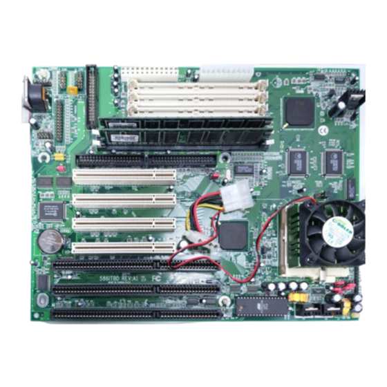
Page 12: Board Layout
Board Layout square denotes pin 1... - Page 13 Refer to Jumpers JP1, JP2, JP15, JP28 and JP29 pages 18-21 Intel and AMD processors JP26 - Modem Ring-on select pages 25-26 JP14 and JP30 page 26 Factory Testing Jumpers Sockets Refer to DM0 and DM1 - DIMM sockets pages 14-15 SM1 to SM4 - SIMM sockets pages 15-17 U1 - ZIF socket...
-
Page 14: System Memory
SIMM, which uses DRAM. Refer to page 12 for the locations of the DIM and SIM sockets. Important: DIM and SIM modules cannot exist on the 586TXD system board at the same time. Use either SIMM or DIMM only, and not both. DIMM The two 168-pin DIMM (Dual In-line Memory Module) sockets use x64 EDO, FPM and SDRAM. -
Page 15: Simm
0 or Bank 1, but you must populate one bank first before going to the next bank. The 586TXD system board can support 8MB to 256MB of memory us- ing 1MBx32, 2MBx32, 4MBx32, 8MBx32, or 16MBx32 72-pin SIMMs. The table on the next page shows the supported SIM modules and their... - Page 16 SIMMs Memory Size 1MBx32 2MBx32 4MBx32 16MB 8MBx32 32MB 16MBx32 64MB The table below summarizes the bank locations and modules needed for the corresponding memory sizes. Bank 0 Bank 1 SIMM1 SIMM2 SIMM3 SIMM4 Memory Size 1MBx32 1MBx32 — — —...
- Page 17 Bank 0 Bank 1 SIMM2 Memory Size SIMM1 SIMM3 SIMM4 96MB 4MBx32 4MBx32 8MBx32 8MBx32 96MB 8MBx32 8MBx32 4MBx32 4MBx32 128MB 16MBx32 16MBx32 — — 128MB — — 16MBx32 16MBx32 128MB 8MBx32 8MBx32 8MBx32 8MBx32 136MB 1MBx32 1MBx32 16MBx32 16MBx32 136MB 16MBx32 16MBx32...
-
Page 18: Cache Memory
Processor Installation The 586TXD allows for easy installation of processors. Make sure all jump- ers are set correctly before applying power or you may damage the proces- sor or system board. Use a needle-nosed plier to move the jumpers if nec- essary. - Page 19 AMD processors use the PR-rating system which is the overall processor performance rating. Jumpers JP15 and JP29 are used to set the voltage of your processor. Make sure these jumpers are set correctly, otherwise your system will hang. The table below shows the External System Bus Clock of the processors supported by the system board and their corresponding PCI Clock and ISA Bus Clock.
-
Page 20: Jumper Settings For Intel ® Processors
® Jumper Settings for Intel Processors ® Intel Processors Ext. System JP28 Bus Clk 60MHz 1-2 On 90/120/150MHz JP28 66MHz* 1-2 Off 100/133/166/200MHz MMX-166/200/233MHz Default ® Intel Processors Freq. Ratio 90/100MHz/MMX-233MHz 1.5x* 1-2 On 1-2 On 2-3 On 1-2 On 120/133MHz 2.5x 2-3 On... -
Page 21: Jumper Settings For Amd Processors
Jumper Settings for AMD Processors PR-Rating JP28 Ext. System Bus Clk 1-2 On K5 PR90/PR120 60MHz K5 PR100/PR133/PR166 1-2 Off 66MHz JP28 K6/166, K6/200, K6/233 66MHz 1-2 Off PR-Rating Freq. Ratio K5 PR90/PR100/ 1.5x 1-2 On 1-2 On PR120/PR133 2-3 On 2-3 On K5 PR166 2.5x... -
Page 22: Installing Upgrade Processors
Installing Upgrade Processors The 586TXD is equipped with a 321-pin Zero Insertion Force (ZIF) socket at location U37 of the sys- tem board. This socket is designed for easy removal of an old proces- sor and easy insertion of an up- grade processor. - Page 23 To install an upgrade processor, do the following: 1. Make sure the handle on the side of the ZIF socket is up. To raise the handle, push it down, slightly pull it out to the side, then raise it as far as it will go. It may be necessary to initially apply a small amount of sideways force to free the handle from its retaining “...
-
Page 24: Installing A Fan/Heatsink
3. Position the CPU above the ZIF socket. Make sure pin 1 of the processor is aligned with pin 1 of the socket. Lower the chip until the pins are inserted properly in their corresponding holes. Remem- ber that very little force is needed to install the processor. If the processor is not easily inserted, verify whether or not pin 1 of the processor is aligned with pin 1 of the socket. -
Page 25: Jumper Settings For Modem Ring-On
C (99 Jumper Settings for Modem Ring-on Jumper JP26 Modem Ring-on Select The 586TXD system board sup- ports Modem Ring-on feature which allows the Soft Power Down (Soft- Off) PC to power on to respond to incoming calls. With a modem in-... -
Page 26: Factory T Esting Jumpers
1. Enable this function by setting JP26 according to the COM port where your modem is connected. 2. If your ATX power supply has an On/Off switch, set this to On so that even when you have shut down (“ soft power off” ) your system, it will always remain in “... -
Page 27: Ports And Connectors
(J7 & J8), two connectors for exter- nal USB ports (JP8 & JP9), and one IrDA connector (U32). Serial Connectors The 586TXD is equipped with two serial connectors at locations JP20 (COM 1) and JP22 (COM 2) of the system board. These serial connec-... -
Page 28: Floppy Disk Drive Controller
378-37A Hex (default) 278-27A Hex Floppy Disk Drive Controller The 586TXD system board is equipped with a shrouded floppy disk header that supports two standard floppy disk drives. You can install any 360KB, 720KB, 1.2MB, 1.44MB, or 2.88MB floppy disk drives. To prevent improper floppy cable installation, the shrouded floppy disk header has a keying mechanism. -
Page 29: Ide Hard Disk Interface
Drive A. IDE Hard Disk Interface The 586TXD system board is equipped with two shrouded PCI IDE headers that will interface four Enhanced IDE (Integrated Drive Elec- tronics) hard disk drives. - Page 30 In a few cases, drives from two different manufacturers will not function properly when used together. The problem lies in the hard drives, not the 586TXD system board. Preparing an IDE Drive for Use IDE disk drives are already low-level formatted, with any bad-track er- rors entered, when shipped by the drive manufacturer.
-
Page 31: Universal Serial Bus Connectors
Using 586TXD with CD-ROM Drives If you encountered problems while using an ATAPI CD-ROM drive that is set in Master mode, please set the CD-ROM drive to Slave mode. -
Page 32: Irda Connector
Connect your IrDA cable to connector U32 on the 586TXD sys- tem board. Make sure “ Onboard IR Controller” in the Integrated Periph- erals setup of the Award BIOS is Enabled. -
Page 33: Installing Expansion Cards
Installing Expansion Cards The 586TXD system board is equipped with 3 dedicated PCI slots, 2 dedicated 16-bit ISA slots and 1 shared PCI/ISA slot. All PCI and ISA slots are bus masters. -
Page 34: Chapter 3: Software Installation
Chapter 3 Software Installation After you power up your system, the BIOS message appears on your screen and the memory count begins. After the memory test, the following message will appear on the screen: Press DEL to enter setup If the message disappears before you respond, restart your system or press the “... -
Page 35: Standard Cmos Setup
ROM PCI/ISA BIOS CMOS SETUP UTILITY AWARD SOFTWARE, INC. STANDARD CMOS SETUP INTEGRATED PERIPHERALS SUPERVISOR PASSWORD BIOS FEATURES SETUP CHIPSET FEATURES SETUP USER PASSWORD POWER MANAGEMENT SETUP IDE HDD AUTO DETECTION HDD LOW LEVEL FORMAT PNP/PCI CONFIGURATION LOAD FAIL-SAFE SETTINGS SAVE &... - Page 36 Date The date format is <day>, <month>, <date>, <year>. Displays a day, from Sunday to Saturday Displays the month, from January to December Month Displays the date, from 1 to 31 Date Displays the year, from 1900 to 2099 Year Time The time format is <hour>, <minute>, <second>.
- Page 37 If the controller of the HDD interface is ESDI, you must select “ Type 1” . If the controller of the HDD interface is SCSI, you must select “ None” . If you select Type “ Auto” , the BIOS will auto-detect the HDD & CD-ROM drive at the POST stage and show the IDE for the HDD &...
- Page 38 Video This category selects the type of video adapter used for the primary system monitor. Although secondary monitors are supported, you do not have to select the type in Setup. The default setting is EGA/VGA (BIOS default, Setup default). Enhanced Graphics Adapter/Video Graphics Array. For EGA, EGA/VGA VGA, SVGA and PGA monitor adapters.
-
Page 39: Bios Features Setup
Base This refers to the amount of base or conventional memory Memory installed on the system board. Extended This is the amount of memory located above 1MB in the Memory memory address map of the CPU. Other This memory size refers to the memory located in the ad- Memory dress space between 640K and 1024K. - Page 40 ! WARNING ! Disk boot sector is to be modified Type “ Y” to accept write or “ N” to abort write Award Software, Inc. After seeing this message, if necessary, you will be able to run an anti- virus program to locate and remove the problem before any damage is done.
- Page 41 Boot Sequence This category determines which drive to search first for the disk operat- ing system (i.e. DOS). The default is A, C, SCSI. The options are: A, C, SCSI; C, A, SCSI; C, CDROM, A; CDROM, C, A; D, A, SCSI; E, A, SCSI; F, A, SCSI; SCSI, A, C; SCSI, C, A; or C only. Swap Floppy Drive Enabled When this option is enabled and the system is booting from...
- Page 42 Security Option This category allows you to limit access to your system and Setup or just to Setup. System The system will not boot and access to Setup will be denied if the correct password is not entered at the prompt. Setup The system will boot, but access to Setup will be denied if the correct password is not entered at the prompt.
-
Page 43: Chipset Features Setup
Enabled Optional shadow is enabled. Disabled Optional shadow is disabled. Chipset Features Setup This section gives you instructions on how to configure the system based on the specific features of the chipset. This chipset manages bus speeds and access to system memory resources. It also coordinates communications between the conventional ISA bus and the PCI bus. - Page 44 ROM PCI/ISA BIOS POWER MANAGEMENT SETUP AWARD SOFTWARE, INC. Power Management : Disabled ** Reload Global Timer Events ** : Enabled IRQ [3-7, 9-15], NMI PM Control by APM : Yes : Disabled Primary IDE 0 Video Off Method : V/H SYNC+Blank Primary IDE 1 : Disabled Video Off After...
- Page 45 Video Off Method This determines the manner in which the monitor is blanked. This selection will cause the system to turn off the vertical and SYNC + horizontal synchronization ports and write blanks to the video Blank buffer. Blank This option only writes blanks to the video buffer. Screen DPMS Initializes display power management signaling.
- Page 46 Suspend When enabled and after the set time of system inactivity, the Mode CPU and onboard peripherals will be shut off. This is used to define the continuous HDD idle time that Power elapses before the HDD enters the power saving mode (mo- Down tor off).
-
Page 47: Pnp/Pci Configuration Setup
Resume by Ring (for ATX power supply only) Set “ Resume by Ring” to COM 1or COM 2. This will depend on the COM port where your modem is connected. Refer to pages 25 and 26 for detailed information. Resume by Alarm (for ATX power supply only) This category allows you to set the day and time to power on your system automatically. - Page 48 ROM PCI/ISA BIOS PNP/PCI CONFIGURATION AWARD SOFTWARE, INC. PCI IDE IRQ Map To : PCI-Auto PNP OS Installed : No Primary IDE INT# Resources Controlled By : Auto Secondary IDE INT# Reset Configuration Data : Disabled Assign IRQ for VGA : Enabled ↑...
-
Page 49: Load Fail-Safe Settings
Reset Configuration Data Enabled The BIOS will reset the configuration data once automatically. Disabled The BIOS will not reset the configuration data. PCI IDE IRQ Map To This category is used to configure your system to the type of IDE disk controller in use. -
Page 50: Load Optimal Settings
Load Fail-Safe Settings (Y/N)? N If you want to proceed, type <Y> and press <Enter>. The default set- tings will be loaded. Load Optimal Settings The “ Load Optimal Settings” option loads optimized settings from the BIOS ROM. Use the Setup default values as standard values for your system. - Page 51 IDE Primary Master/Slave PIO and IDE Secondary Master/Slave Your system supports five modes, 0 (default) to 4, which primarily differ in timing. When Auto is selected, the BIOS will select the best available mode after checking your hard drive or CD-ROM. Auto The BIOS will automatically set the system according to your hard disk drive’...
- Page 52 Disables the onboard serial port 1 and/or serial port 2. Onboard IR Controller The 586TXD system board supports IrDA function for wireless connec- tivity between your computer and peripheral devices. You may not use IrDA (U32) and the COM 2 serial port (JP22) at the same time. If you are using the COM 2 serial port, make sure “...
- Page 53 IR Address Select This is used to select an I/O address for the IrDA peripheral/device installed. The options are: 3F8H, 2F8H, 3E8H and 2E8H. Default setting: 2E8H. IR Mode Set “ IR Mode” to the type of IrDA standard supported by your IrDA peripheral/device.
-
Page 54: Supervisor Password
If you selected EPP, “ EPP Mode Select” will appear. This option applies to standard specification. The options are EPP1.9 and EPP1.7. Default setting: EPP1.7. If you selected ECP, “ ECP Mode Use DMA” will appear. This is used to select a DMA channel for the parallel port. -
Page 55: User Password
User Password If you want another user to have access only to your system but not to setup, set a user’ s password with the “ System” option selected in the BIOS Features Setup. If you want a user to enter a password when trying to access setup, set a user’... - Page 56 Hard Drive Mode The system board supports three HDD modes: Normal, LBA and Large. If your hard disk drive does not support LBA mode, the “ LBA” option will not be displayed. If your HDD has 1024 or fewer cylinders, the “ Large” option will not be displayed.
-
Page 57: Hdd Low Level Format
no. Cylinders (1024) x no. Heads ( 255) x no. Sectors ( 63) x bytes per sector ( 512) 8.4 gigabytes Large Mode Large mode is the extended HDD access mode supported by the sys- tem board. Some IDE HDDs have more than 1024 cylinders without LBA support (in some cases, you may not want the LBA mode). -
Page 58: Save & Exit Setup
ROM PCI/ISA BIOS CMOS SETUP UTILITY AWARD SOFTWARE, INC. Hard Disk Low Level Format Utility No. CYLS HEAD SELECT DRIVE BAD TRACK LIST PREFORMED Current select drive is : C DRIVE: C CYLINDER: 0 HEAD: 0 LANDZ SECTOR SIZE CYLS HEAD RECOMP MODE... -
Page 59: System Error Report
Type “ Y” and press <Enter>. The system will reboot and you will once again see the initial diagnostics on the screen. If you wish to make any changes to the setup, press <Ctrl> <Alt> <Esc> simultaneously or <Del> after memory testing is done. System Error Report When the BIOS encounters an error that requires the user to correct something, either a beep code will sound or a message will be dis-... - Page 60 CMOS CHECKSUM ERROR Checksum of CMOS is incorrect. This can indicate that CMOS has be- come corrupt. This error may have been caused by a weak battery. Check the battery and replace if necessary. DISPLAY SWITCH IS SET INCORRECTLY The display switch on the motherboard can be set to either mono- chrome or color.
-
Page 61: Driver Installation
The BIOS reports memory test fail if the memory has error(s). Driver Installation To install the IDE drivers supported by the 586TXD system board, please refer to the “ Readme” file contained in the provided diskette for detail information. All steps or procedures to install software drivers are subject to change without notice as the softwares are occassionally up- dated. - Page 62 Warning: Do not install Windows 95 from your CD-ROM drive. You will not be able to install the operating system successfully. This is because Windows 95 does not support hardware drivers that would recognize the TX chip. ® Installing IDE Drivers for Windows The table below shows the INF files that must be installed into your system.
- Page 63 9. Change to A: or B: prompt. Type “ CD OSR2” or “ CD OSR2.1” and press <Enter>. 10. Copy “ MSHDC.INF” , “ MACHINE.INF” and “ USB.INF” from the dis- kette to drive C. Ex: A:\OSR2>COPY MSHDC.INF C: A:\OSR2>COPY MACHINE.INF C: A:\OSR2.1>COPY USB.INF C: (for Win95 OSR2.1 only) 11.
-
Page 64: Chapter 4: Troubleshooting Checklist
Chapter 4 Troubleshooting Checklist This chapter of the manual is designed to help you with problems that you may encounter with your personal computer. To efficiently troubleshoot your system, treat each problem individually. This is to ensure an accurate diagnosis of the problem in case a problem has multiple causes. - Page 65 Hard Drive Hard disk failure. 1. Make sure the correct drive type for the hard disk drive has been entered in the BIOS. 2. If the system is configured with two hard drives, make sure the bootable (first) hard drive is configured as Master and the second hard drive is configured as Slave.
- Page 66 3. Verify that the attached serial device works by attaching it to a serial port that is working and configured correctly. If the serial device does not work, either the cable or the serial device has a problem. If the serial device works, the problem may be due to the onboard I/O or the address setting.
-
Page 67: Appendix A: Types Of Modules
Appendix A Types of Modules The following modules have been tested with this board. Most untested brands will work but a few may fail to do so. DIMM Brand Chip Number Fujitsu 1MBx64 D4516161G5-7JF 1MBx64 D4516161G5-7JF 2MBx64 KM416S1120AT-G12 2MBx64 D4516821G5-A12-7F 2MBx64 Mitsubishi M5M4V16S30CTP... - Page 68 Brand SIMM Chip Number 4MBx32/x36 Mitsubishi 422A06-70 4MBx32/x36 Hitachi 5117400AS-70 4MBx32 4217400-60 4MBx32 4217405-70 (EDO) 8MBx32 4217405-60 (EDO) 16MBx32 71C16100AJ6...
-
Page 69: Appendix B: Memory And I/O Maps
Appendix B Memory and I/O Maps Memory Address Map Address Name Function 0000000 to 640KB System System Board Memory 009FFFF Board RAM 00A0000 to 128KB Video Reserved for Graphics 00BFFFF Display Memory Display Memory 00C0000 to 160KB I/O Reserved for ROM on 00E7FFF Expansion ROM I/O Adapter Card... - Page 70 I/O Address Map I/O Address Function 0000-001F DMA Controller 1, 8237A-5 0020-003F Interrupt Controller 1, 8259A, Master 0040-005F Timer, 8254-2 0060-006F 8742 (Keyboard Controller) 0070-007F Real-time Clock, NMI (Non-maskable Interrupt) Mask 0080-009F DMA Page Memory, 74LS612 00A0-00BF Interrupt Controller 2, 8259A 00C0-00DF DMA Controller 2, 8237A-5 00E8...
-
Page 71: Appendix C Connectors
Appendix C Connectors Connectors USB 1 connector USB 2 connector JP20 COM 1 serial port JP22 COM 2 serial port JP27 AT power connector ATX power connector Parallel printer port Floppy disk drive connector IrDA connector Primary IDE hard disk drive connector Secondary IDE hard disk drive connector... - Page 72 PS/2 mouse port AT keyboard port PS/2 keyboard port keyboard lock connector Speaker connector Reset switch connector SMI switch connector Power switch connector Green LED connector HDD LED connector ATX LED connector...
- Page 73 Pin Assignments JP8 - USB 1 connector JP9 - USB 2 connector Function Function -Data -Data +Data +Data Ground Ground Ground J14 - PS/2 mouse port U32 - IrDA connector Function Function Mouse Data IrTX N. C. Ground Ground IrRXL N.C.
-
Page 74: Addendum (Rev. Aa+)
Addendum 586ITB Rev. AA + Chipset Features Setup ROM PCI/ISA BIOS CHIPSET FEATURES SETUP AWARD SOFTWARE, INC. Auto Configuration : Enabled Power-Supply Type : AT DRAM Timing : Normal DRAM Leadoff Timing : 11/7/4 DRAM Read Burst (EDO/FP) : x444/x444 DRAM Write Burst Timing : x444 Fast EDO Lead Off... - Page 75 ® Intel Processors Processors - Ext. Speed JP28 JP14 1-2 On 1-2 On 1-2, 3-4 On 90MHz - 60MHz 100MHz - 66MHz 1-2 On 1-2 On 1-2, 3-4 On 1-2, 3-4 On 120MHz - 60MHz 2-3 On 1-2 On 2-3 On 1-2 On 1-2, 3-4 On 133MHz - 66MHz...
- Page 76 ® Jumper Settings for Cyrix Processors ® The 586ITB now supports Cyrix 6x86L processors. Please refer to the jumper settings shown below. Processors - Ext. Speed JP28 JP14 JP15 2-3 On PR150 - 60MHz 1-2 On 5-6, 7-8 On 1-2 Off, 3-4 On PR166 - 66MHz 2-3 On 1-2 On...
- Page 77 Lemel web site: www.synnex.com.tw This publication contains the information that is protected by copyright. No part of it may be reproduced in any form or by any means or used to make any transformation/adaptation without the prior written permission from the copyright holders. All product names mentioned are trademarks or registered trademarks of their respective companies.
Need help?
Do you have a question about the 586TXD and is the answer not in the manual?
Questions and answers