Advertisement
Table of Contents
- 1 Table of Contents
- 2 Important Information
- 3 Preparation
- 4 Schematic Installation and Routing Diagram
- 5 Connection Overview, Adapter Lead and Power Cable
- 6 Installing and Connecting Adapter Lead and Power Cable
- 7 Installing Amplifier
- 8 Installing Tweeters and Woofers/MID-Range Speakers at Front
- 9 Installing Rear Coax Speakers
- 10 Affixing Stickers
- 11 Concluding Jobs/Encoding
- 12 Initial Use
- Download this manual
Parts and Accessories
Installation Instructions
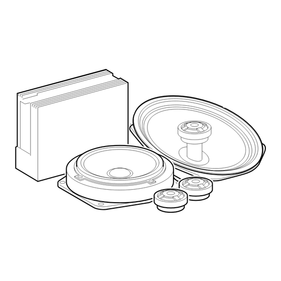
Installation kit, sound module
MINI (R50/R53) Left-hand drive (LHD)
Not suitable for vehicles with on-board monitor radio
Not suitable for vehicles with "NG*" car radio
Not suitable for vehicles with SA 674 ("harman/kardon" HiFi system)
The installation time of approx. 2.5 hours can vary depending on the condition and equipment of
the vehicle.
Retrofit/installation kit No. 82 83 0 136 491
* New Generation
Retrofit/installation kit No.: 82 83 0 136 491
Installation instruction No.: 01 29 0 139 395
Status: 06.2001
Advertisement
Table of Contents

Summary of Contents for Mini R50
- Page 1 Parts and Accessories Installation Instructions Installation kit, sound module MINI (R50/R53) Left-hand drive (LHD) Not suitable for vehicles with on-board monitor radio Not suitable for vehicles with "NG*" car radio Not suitable for vehicles with SA 674 ("harman/kardon" HiFi system) The installation time of approx.
-
Page 2: Table Of Contents
Contents Section Important Information..........Preparation . -
Page 3: Important Information
Important Information Read out the defect code memories before disconnecting the battery and on completion of assembly. It is possible that the connections and/or pin assignments change during the course of further development. For this reason, the currently valid ETM (Electrical Troubleshooting Manual) must always be used for installation purposes. -
Page 4: Preparation
Preparation Carry out quick test Disconnect negative terminal of battery The following components must be disassembled or re- moved beforehand: Battery with battery box Instrument cluster Radio Front left door trim panel Front right door trim panel Remove woofers/mid-range speakers in front doors (no longer required) Release rear left side trim panel in front area Release rear right side trim panel in front area... -
Page 5: Schematic Installation And Routing Diagram
Schematic installation and routing diagram Amplifier Fuse (20 A) Power cable with fuse holder at B+ (see B2 on Page 6) Adapter lead Woofer/mid-range speaker Tweeter Coax speaker Car radio connector Connector for standard wiring harness 10 Vehicle ground connection (see A3 on Page 6) Retrofit/installation kit No.: 82 83 0 136 491 Installation instruction No.: 01 29 0 139 395 Status: 06.2001... -
Page 6: Connection Overview, Adapter Lead And Power Cable
Connection overview, adapter leads and power cables I t e m Description Adapter lead 17-pin pin housing 17-pin socket housing Cable shoe 6 mm 25-pin socket housing Stranded wire Flat-pin terminal Power cable Fuse holder with fuse (20 A) Cable shoe 6 mm The X-designations marked with * apply to this overview only and do not refer to the general service documentation. -
Page 7: Installing And Connecting Adapter Lead And Power Cable
Installing and connecting adapter lead and power cable Retrofit/installation kit No.: 82 83 0 136 491 Installation instruction No.: 01 29 0 139 395 As illustrated, install adapter lead A as follows: Route branch A 1 and A 2 to installation location of radio. -
Page 8: Installing Amplifier
Installing amplifier Retrofit/installation kit No.: 82 83 0 136 491 Installation instruction No.: 01 29 0 139 395 Unscrew Torx screws (1). Remove connector (2), white 18-pin connector housing, together with retaining fixture from carrier (5). Remove sticker (3) and clean adhesion point with spirits. - Page 9 Installing amplifier Retrofit/installation kit No.: 82 83 0 136 491 Installation instruction No.: 01 29 0 139 395 Do not soil adhesive surface of adhesive strip (3) when installing amplifier (1). 3 Install amplifier (1) as illustrated, turn into horizontal position and push upward. Route wiring harness (2) up to amplifier (1).
-
Page 10: Installing Tweeters And Woofers/Mid-Range Speakers At Front
Installing tweeters and woofers/mid-range speakers at front Retrofit/installation kit No.: 82 83 0 136 491 Installation instruction No.: 01 29 0 139 395 The figures show the working steps on the left-hand side of the vehicle. The same procedure is to be followed analogously on the right-hand side of the vehicle. -
Page 11: Installing Rear Coax Speakers
Installing rear coax speakers Retrofit/installation kit No.: 82 83 0 136 491 Installation instruction No.: 01 29 0 139 395 The figure shows the working steps on the left-hand side of the vehicle. The same procedure is to be followed analogously on the right-hand side of the vehicle. -
Page 12: Affixing Stickers
Affixing stickers Install front left and right door trim panels. Install rear left and right side trim panels. 3 It is important to precisely observe the following procedure for affixing the stickers to en- sure they remain adhered permanently. The speaker covers must be dry, clean, free of dust and grease. The temperature during the adhesion process must be at least 15 ûC. -
Page 13: Concluding Jobs/Encoding
Refer to the supplementary Operating Instructions for further information on the radio settings to ensure optimum sound reproduction of the MINI Sound module. Retrofit/installation kit No.: 82 83 0 136 491 Installation instruction No.: 01 29 0 139 395 Status: 06.2001...


Need help?
Do you have a question about the R50 and is the answer not in the manual?
Questions and answers