Table of Contents
Advertisement
Quick Links
Advertisement
Table of Contents

Subscribe to Our Youtube Channel
Related Manuals for Mini Wallbox Plus


Summary of Contents for Mini Wallbox Plus
- Page 1 MINI Wallbox Plus INSTRUCTIONS FOR USE. ORIGINAL MINI ACCESSORIES.
-
Page 3: Table Of Contents
MINI Wallbox Plus Instructions for use Contents 1 Information 2 Overview 3 Specifications 4 Installation 5 Connect Terminal 6 Configuration via Wallbox Installation App 7 Commissioning 8 Operation 9 Status LED information 10 Maintenance 11 Technical data 12 Disposal © 2024 BMW AG, Munich/Deutschland Reprinting, even in part, requires the express written permission of BMW AG, Munich. -
Page 4: Information
Do not make any unauthorized changes or modifications to the MINI Wallbox Plus. ■ Repair work to the MINI Wallbox Plus is not permitted and may only be completed by the ■ manufacturer or a trained expert (MINI Wallbox Plus replacement). - Page 5 Ensure that the MINI Wallbox Plus is not damaged by incorrect handling (housing cover, ■ internal parts, etc.). If it is raining or snowing and the MINI Wallbox Plus is installed outdoors, do not open the ■ terminal panel cover.
- Page 6 This manual and the functions described in it are valid for devices of the following type: MINI Wallbox Plus (MINI part number 61 90 5 A7A 8B1) This manual is designed exclusively for trained personnel. These are people who, as a result of their training, skills and experience and their knowledge of the relevant standards, can assess the work assigned to them and identify possible dangers.
- Page 7 1.4 Package Mounting template Torx T20 anti-theft screw Mounting bracket Middle cover screw (4X) Cable holder M6 Hex Socket Cable holder screw (3X) Cosmetic cover Setup Card, Charging Card (2X) No.8 wood screws (4x) Safety Guide Torx T30 mounting bolts (3x) M32 Cable gland 1/4‘...
- Page 8 Defects or damage caused by installation work which was not carried out as specified in the MINI ■ Wallbox Plus installation instructions. Defects or damage caused by the product not being used as specified in the MINI Wallbox Plus ■ operating manual.
-
Page 9: Overview
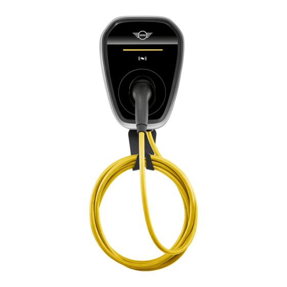
2 Overview 2.1 Display and controls 61 90 5 A7A 8B1 ■ 1. Cosmetic cover 2. Vehicle connector inlet 3. Vehicle connector 4. LED indicator 5. RFID Reader 6. Middle cover 7. Mounting bracket 8. Cable holder... -
Page 10: Specifications
- At which the installation surface does not have sufficient strength to withstand the mechanical stresses. If possible, install the MINI Wallbox Plus so that it is protected from direct rainfall so as to avoid the ■ effects of weather, icing, damaged by hailstones or the like. - Page 11 When selecting the circuit breaker, the standard value of the rated conditional residual short-circuit current shall be 1500A for the MINI Wallbox Plus. Also take into consideration the increased ambient temperatures in the control cabinet. In certain circumstances this may require a reduction in the charging current settings to increase the system availability.
- Page 12 When selecting the supply cable, take into account the possible reduction factors and the increased ambient temperatures in the internal connection area of the MINI Wallbox Plus, see the temperature rating of the supply terminals. In certain circumstances, this may require an increase in the cable cross- section and an adjustment in the temperature resistance of the supply cable.
-
Page 13: Installation
Ideally, the MINI Wallbox Plus should be stored for a few hours in advance at the installation site. If this is not possible, the MINI Wallbox Plus should not be stored in low temperatures (< 5 °C) overnight outdoors or in a vehicle. - Page 14 4.2 Recommended installation positions When selecting the installation position, taken note of the position of the charge connector on your vehicle and the direction in which you normally park it. 4.3 Required distance Follow applicable accessibility requirements for the mounting position. The unit must be mounted at a sufficient height from ground such that the storage height is located between 1,000mm (39 inch) and 1.2m (4 ft).
- Page 15 4.4 Mounting the MINI Wallbox Plus 1. The product is a stationary equipment mounted on the wall. It includes a mounting template to mark the screw locations for the mounting bracket and cable holder (optional). 2. Secure the mounting bracket to the wall. The cable holder is optional and depicted in the figure for demonstration purposes.
- Page 16 4.5 Removing the covers 5. Remove the cosmetic cover. 6. Use a T20 screw driver to remove the screws securing the middle cover. Torque: 1.4 Nm (12 lb·in) 7. Remove the middle cover.
- Page 17 4.6 Secure the anti-theft screw 8. The hole for the anti theft screw is covered by a void label. 9. Tighten the anti theft screw through the void label.
-
Page 18: Connect Terminal
The stripped length of the input cable shall follow the indication in the wallbox. It’s also possible to connect the MINI Wallbox on a single phase basis. Connect terminals L1, N, and PE for this purpose. - Page 19 Connect the external energy meter for monitoring the domestic power connection. Configuration of the energy meter must be done in the installation Wizard in the Wallbox Installation App. Energy meter connection is necessary to enable MINI Connected Home Charging Features. Connect the RS485 interface with the shielded and twisted connection cables ( >...
- Page 20 61 90 5 A7A 8B1 ■ Connect the meter with power line according to the instruction on manual of corresponding meter. Connect the Peak Shifting interface with the shielded and twisted connection cables ( > 0.5 mm², max. 30 m) 61 90 5 A7A 8B1 Definition: PS_2: pin 1...
-
Page 21: Configuration Via Wallbox Installation App
6 Configuration via Wallbox Installation App 6.1.1 Wallbox Installation App To configure the MINI Wallbox Plus the Installation Wizard in the Wallbox Installation App must be used. Without finishing the Installation Wizard successfully, charging is not possible . The installer or MINI service partner must use the service and installation app in order to configure the device, download charging history and diagnostics, update the firmware and trouble shoot. -
Page 22: Commissioning
7 Commissioning Install the middle cover. Torque: 1.0 Nm (8.7 lb·in) Install and lock the cosmetic plate. An audible click sounds denotes a closed faceplate. -
Page 23: Operation
8 Operation The MINI Wallbox Plus is factory wise delivered with disabled access control via app. Please adjust configuration in the Wallbox Installation App accordingly if you want to use access control. Please refer to section 6. For access control via RFID cards, charging cards need to be registered using the Set-Up Card. The MINI Wallbox Plus comes with two RFID cards that can be registered for this purpose. - Page 24 8.2 Stop charging with disabled access control 1. Stop charging session at the vehicle. 2. Disconnect the vehicle connector from the vehicle inlet. 3. Place the vehicle connector back into the vehicle connector inlet of the MINI Wallbox Plus.
- Page 25 8.3 Start charging with enabled access control 1. Connect the vehicle connector to vehicle inlet. 2. Hold the RFID card in front of the RFID reader to authorize and intiate the start of the charging session.
- Page 26 1. Stop charging session at the vehicle, via the my MINI App or RFID card. 2. Disconnect the vehicle connector from the vehicle inlet. 3. Place the vehicle connector back into the vehicle connector inlet of the MINI Wallbox Plus.
- Page 27 8.5 RFID Card Registration The MINI Wallbox Plus Plus uses two different kinds of RFID Cards: A Setup Card to notify Wallbox to turn on/off a registration mode ■ Charging Cards to control start/stop charging ■ Please refer to Chapter 8.1 and 8.2 on how to charge using the charging card.
- Page 28 8.5.1 Registration of new Charging Cards 1. The MINI Wallbox Plus needs to be powered on, DO NOT connect the charging cable with the vehicle. The LED bar should display a steady yellow light. 2. Hold the setup card in front of the RFID reader to start the registration mode of new Charging Cards.
- Page 29 The MINI Wallbox Plus comes with a preregistered Set-Up card that can be used to register new Charging Cards. A new Set-Up Card can be registered via the Wallbox Installation App (see section 6) .
- Page 30 The current list of supported Smart Energy Modules can be found in chapter 6.2. 8.6.1 Load-optimized charging Optimizing the charging power of the MINI Wallbox Plus while taking the household load into account ensures that the total available load at the grid connection point is not exceeded. Dynamic control of load distribution is particularly important in regions with low local grid point capacities.
- Page 31 On an exemplary day there are periods with more and less available solar power, resulting in a combined charging power for the MINI Wallbox Plus (displayed by the blue line). When sufficient solar power is available, like in the displayed periods 2 and 4, charging is done exclusively with electricity from the photovoltaic system.
-
Page 32: Status Led Information
9 Status LED information LED Indicator Status Yellow, flashing from left to MINI Wallbox Plus initialization in progress. right MINI Wallbox Plus is suspended temporarily. Yellow Vehicle is not connected, standby. Yellow, breathing Vehicle is charging. Error Yellow (S1/S2/S3), Red (S4) Communication module is damaged or defective on standby. -
Page 33: Maintenance
1. Check the possible causes of the error in the Wallbox Installation red. App. 2. Switch off the supply voltage to the MINI Wallbox Plus using the appropriate mains isolation device. 3. Disconnect the vehicle connector and switch on the supply voltage again. -
Page 34: Technical Data
11 Technical data Electrical data Part number 61 90 5 A7A 8B1 Vehicle connector Type 2 plug Input/output rating 380-415V~, 32A, 50/60Hz, three phases 100-240V~, 32A, 50/60Hz, single phase Input wiring PE, L1, L2, L3, N Grounding system TN/ IT/ TT Rated current (Adjustable rated 0A, 6A, 10A, 12A, 16A, 20A, 24A, 32A current via Wallbox Installation... - Page 35 Interfaces Indicator LED bar indicator Communication Bluetooth, RFID, Ethernet, ISO15118, OCPP , 4G, WiFi Ambient conditions Operating temperature -40 °C ~+50 °C Temperature properties This is not a safety device, it is just an operating function. The specified operating temperature range must not be exceeded. The device supplies the charging current continuously at the specified operating temperature ranges.
-
Page 36: Disposal
12 Disposal After correctly decommissioning the device, please have it disposed of by the service department in compliance with current waste disposal regulations. The electrical and electronic devices including accessories must be disposed of separately from general household waste. There are instructions on the product, in the instructions for use or on the packaging. - Page 38 01 29 5B43536 02/2024 (V/Z)
Need help?
Do you have a question about the Wallbox Plus and is the answer not in the manual?
Questions and answers