
Related Manuals for Mountz HDC-40i


Summary of Contents for Mountz HDC-40i
- Page 1 Feb 2016 Operation Manual Hybrid Digital Screwdriver HDC-40i, HDC-35i 1080 N 11th St San Jose CA 95112 www.mountztorque.com 408.292.2214...
- Page 2 Hybrid Digital Screwdriver HDC-40i, HDC-35i Quick Set Up Installation: 1. After unpacking system, please connect cable to driver and controller. Be aware that cable's ends are indetified so one specific end goes to controller and other to driver. Cable must snap in completelly, please verify both ends are fully connected.
-
Page 3: Table Of Contents
Index ■ General & Specific safety rules 1. Products introduction 2. Key features 3. Specification 3.1 Driver 3.2 Manual screwdriver models 3.3 Automation screwdriver models 3.4 Controller (HDC) specification 4. LAY-OUT 4.1 Screwdriver LAY-OUT 4.2 HDC Controller LAY-OUT 4.3 HDC Controller Dimensions 5. - Page 4 5.11 25P I/O port configuration 5.11.1 25P I/O configuration (I) - for Sensor 5.11.2 25P I/O configuration (II) - for PLC 5.11.3 25P I/O configuration (III) - for Sensor + PLC 5.11.4 25P Interface schematic - INPUT 5.11.5 25P Interface schematic - OUTPUT 5.11.6 Wiring of the Alarm signal to the Tower Lamp 5.11.7 Error code pin composition on 25P Output 5.12 25PIN I/O Timing Chart...
- Page 5 7.2.3 Command 7.2.4 Check sum 7.2.5 Details of Command 8. Auto fastening data output through USB port 9. PC communication software, Hi-Manager 9.1 Software install 9.2 How to use 9.3 Parameter setting on Hi-Manager 1) Fastening Setting 2) Controller Setting 3) Screw Count Setting 4) Multi Sequence 5) Driver setting...
- Page 6 1. GENERAL SAFETY RULES WARNING! Read and understand all instructions. Failure to follow all instructions listed below, may result in electric shock, fire and/or serious personal injury SAVE THIS INSTRUCTIONS 1.1 Work Area Keep your work area clean and well lit. Cluttered benches and dark areas invite accidents.
- Page 7 personal injury. Dress properly. Do not wear loose clothing or jewelry. Contain long hair. Keep your hair, clothing, and gloves away from moving parts. Loose clothes, jewelry, or long hair can be caught in moving parts. Avoid accidental starting. Be sure switch is off before plugging in. Carrying tools with your finger on the switch or plugging in tools may result in personal injury.
- Page 8 2. SPECIFIC SAFETY RULES 2.1 Hold tool by insulated gripping surfaces when performing an operation where the cutting tool may contact hidden wiring or its own cord. Contact with a "live" wire will make exposed metal parts of the tool "live" and shock the operatior. 2.2 Never lubricate aerosol oil on to the electrical part.
-
Page 9: Products Introduction
1. Product Introduction A driver system consists of screwdriver with built-in BLDC motor, controller which provide and control the DC power and pressed air to the screwdriver. They are connected together with the special cable. 1) Standard Item 2) Optional accessories AC adapter U-2 Interface converter USB cable... -
Page 10: Driver
3. Screwdriver 3.1 Specifications Item Specification Remark DC40V, 3A max DC35V, 4A max El. Power (HDC-40i) (HDC-35i) Motor Maxon BLDC motor Dimension refer 3.2 screwdriver model Torque range refer 3.2 screwdriver model 0.1 Kgf.cm/scale Speed range refer 3.2 screwdriver model +/- 5%... -
Page 11: Manual Screwdriver Models
4.7 - 13.4 HD150P 500-1,700 0.44 Push HD220 6.0 - 19.0 400-1,250 0.44 Lever HD220P 6.0 - 19.0 400-1,250 0.44 Push HDC-40i HD350 8.6 - 30.3 300-740 0.51 Lever HD350P 8.6 - 30.3 300-740 0.51 Push HD450 8.6 - 39.0 300-600 0.51 Lever 8.6 - 39.0... -
Page 12: Automation Screwdriver Models
Controller (Lbf.in) (rpm) HDA150 4.7 - 13.4 500-1,700 HDA220 6.0 - 19.0 400-1,250 HDC-40i HDA350 8.6 - 30.3 300-740 HDA450 8.6 - 39.0 300-600 ** Add suffix "V" after model name for vacuum pick-up assy option DIMENSION HDA150, HDA220, HDA350, HDA450 1080 N 11th St San Jose CA 95112 www.mountztorque.com 408.292.2214... -
Page 13: Controller (Hdc) Specification
3.4 Controller (HDC) specification Item Specification Model HDC-40i HDC-35i Input (Electric) AC110VC or AC220V, 50~60Hz Input (air presure) Min 4.5 bar / Max 6 bar Output (Electric) DC40V, 3A DC35V, 4A Fuse AC250V 10A AC250V 15A Dimension / Weight refer the drawing Torque 5-45 Kgf.cm... -
Page 14: Screwdriver Lay-Out
LAY-OUT 4.1 Screwdriver LAY-OUT (1) Screwdriver for HDC-40i (2) Screwdriver for HDC-35i 1080 N 11th St San Jose CA 95112 www.mountztorque.com 408.292.2214... -
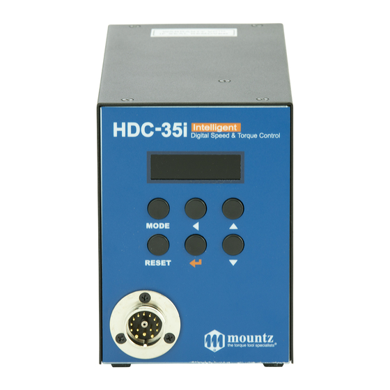
Page 15: Hdc Controller Lay-Out
LAY-OUT 4.2 HDC Controller LAY-OUT 1080 N 11th St San Jose CA 95112 www.mountztorque.com 408.292.2214... -
Page 16: Hdc Controller Dimensions
4.3 HDC controller Dimensions [HDC-40i Controller] unit : mm These two screws can be removed for mounting Two M3 thread holes for mounting controller Two screws at the side can be removed for extra mounting holes. [Caution] Screw should not go through over 5mm inside Dimension / Weight 97(w) 222(d) 129(h)mm / 2.1Kg... - Page 17 [HDC-35i Controller] unit : mm Two M3 thread holes for mounting controller Two screws at the side can be removed for extra mounting holes. [Caution] Screw should not go through over 5mm inside Dimension / Weight 104(w) 226.4(d) 144(h)mm / 2.6Kg 1080 N 11th St San Jose CA 95112 www.mountztorque.com 408.292.2214...
-
Page 18: Front Panel Of Controller
5. Operation 5.1 Front panel of controller 1) FND Display (5 digit) 1080 N 11th St San Jose CA 95112 www.mountztorque.com 408.292.2214... -
Page 19: Key Buttons
2) Key Buttons button : MODE By pressing the MODE button, it circulate Auto, mode. Auto means operating. Log-in and Parameter Before parameter mode, password required. Every settings is possible in Parameter mode. button Log-in is required for parameter setting with password Log-in Mode Initial password "0"... -
Page 20: Parameter Number Group
Enter button It select or save the chosen display Parameter Mode Jog Mode Manual start by button RESET button It returns to the previous mode. Also it reset the error 5.2 Parameter number group Number Main contents Description 1- 8 Torque Save the target torque from 1-8 11-18... - Page 21 5.3 Preset number and parameters The preset numbers from 1 to 8 are effected together with parameter 1~8 for torque, parameter 11~18 for speed, parameter 21~28 for max. angle, parameter 31~38 for min. angle, parameter 41~48 for soft start and parameter 51~58 for torque tuning. 1st data 2nd data 3rd data...
-
Page 22: Torque, Speed & Angle Setting (I) - By Pc Program
5.4 Torque, speed & angle setting (I) - by PC program Set torque, speed & angle on the PC program and upload to the HDC controller, then parameters will be set in the HDC controller. Please refer the details to the article 9. PC program, Hi-Manager on page 65. [ HDC setting menu on Hi-manager pc program ] 1080 N 11th St San Jose CA 95112 www.mountztorque.com 408.292.2214... -
Page 23: Torque, Speed & Angle Setting (Ii) - On The Front Panel
5.5 Torque, speed and Angle setting (II) - on the front panel Log-in is required whenever controller power is OFF and ON for choosing parameter mode. Once log-in with password, it displays Log-IN on mode circulation. Password can be changed on P89 All parameters including torque, speed are changed or set in Parameter mode. -
Page 24: Details Of Each Parameter Numbers
5.6 Details of each parameter numbers 1) Torque Number Unit Range Initial P1~8 0.01 (Kgf.cm) Each number from P1 to 8 contains the torque value for Preset Description # 1 to 8. The value of parameter 1 is the target torque saved in Preset # 1. - Page 25 4) Max Angle control Number Unit Range Initial P21~28 0.1 turn (36°) 0 ~ 30.0 "0" : No use "0.1~30.0" : Value of rotating turn (angle) Angle control stop Function #1 The driver stops at the set turn(angle) and provide fastening complete OK output signal.
- Page 26 5) Minimum Angle for Fastening Quality control Number Unit Range Initial P31~38 0.1 turn 0 ~ 30.0 Minimum angle can be set as a threshold point For fastening quality control. "0" : No use "0.1~30.0" : Value of rotating turn (angle) Function #1 No torque up NG after Min.
- Page 27 6) Cycle Reset & key button lock on front panel Number Unit Range Initial 0 or 1 Cycle reset is allowed by the Reset key button on the front Description panel " 0 " Disable, " 1 " Enable 0 or 1 Front key button lock control on the front panel Description on the front panel...
- Page 28 9) Middle count number setting Number Unit Range Initial 0 ~ 99 When the count number reaches to the Middle count number, count complete signal OUT become ON till the total count is Description completed. Signal types on P70 are ignored on this feature "0"...
- Page 29 12) Error display time setting P60 Number Unit Range Initial 0 ~ 10 Error display and reset after the below set time Description "0" : Manual reset by RESET button "1 ~10.0 sec" : Auto reset after set time 13) Torque unit Number Unit Range...
- Page 30 If there is difference between set torque and reading torque on the torque tester, the output torque can be adjusted from -20% ~ +20% This compensation effects to whole range of torque. This torque compensation value is saved in screwdriver itself. Description 80 (-20%) ---->...
- Page 31 Number Unit Range Initial 0 or 1 The beep sound can be off Description 0 : ON 1 : OFF 18) Time limit for fastening, Loosening and motor stall Number Unit Range Initial P66~68 0.1 sec 0 ~ 60.0 It prevent the continuous running over the preset time in direction of fastening and loosening for safety operation.
- Page 32 Number Unit Range Initial 0 or 1 Reverse rotation control Description 0 : Deactivated 1 : Activated 20) FND Display type Number Unit Range Initial 1 ~ 5 One of 5 types of display can be selected. "1" : Preset no. + Speed Example) -->...
- Page 33 21) COUNT complete signal type at count port (pin 4) Number Unit Range Initial 0 ~ 3 It select the type of Count Finish signal of the Direct Sensor port. ( 2- Count Start signal 4-Count Finish signal Description "0" : It provide 500ms of pulse type count complete signal after fasten all set numbers.
- Page 34 22) Function of F2 button of screwdriver related with Counter port Number Unit Range Initial 0 ~ 3 function of F2 button on the screwdriver It selects the 0 : Disable 1 : Cancel last count 2 : Screw feeding signal (through torque-up output 3 : Preset/Model # select by F1(up) &...
- Page 35 23) Multiple hit Number Unit Range Initial 1 ~ 5 Clutch activating times can be selected from 1 to 5.It choose "1" : Single hit "2" : Double hit Description "3" : Triple hit "4" : Quadruple hit "5" : 5 times hit 24) Number of preset # select by F1 &...
- Page 36 26) Model select for screw count Number Unit Range Initial 0 or 1 HDC has 8 different models for screw count. Each model is programmable with the max. 20 preset numbers in a cycle process. To use this feature, P74 should be enabled "0"...
- Page 37 27) Count start(IN) & finish(OUT) signal type Number Unit Range Initial 0 ~ 3 For monitoring and qualifying the number of screws, HDC should receive the count START signal and STOP(Finish) signal in some application. HDC provides the count complete signal out when it reach to the target number.
- Page 38 28) Time LIMIT from Count start (P76_"2" selected) Number Unit Range Initial 0.1 sec 0 ~ 999.9 The fastening time limit from Count START for NG judgment. The fastening work should be finished within the set time. Description Otherwise, the work-piece will leave the working area. * Refer to the article 5.13.2 for details 29) No torque-up NG by Min.
- Page 39 30) Torque-up NG before Min. set angle(turn) on P31~38 Number Unit Range Initial 0 ~ 1 Torque-up NG before the set turn on P31~38 --> error code E307 Description "0" : Disable "1" : Enable 31) Time setting for SLEEP mode Number Unit Range...
- Page 40 Description - Controller should be reset to the factory setting when the connected driver is replaced to other model. - Controller should be powered off whenever completed resetting. 34) F1 Button on screwdriver (P84 : HDC-40i only) Number Unit Range...
- Page 41 36) Auto Fastening Data output Number Unit Range Initial 0 ~ 1 Monitoring data can be output automatically through USB(RS-232) without data request command protocol Description 0 : Hi-Manager 1 : Auto output Enable 37) Fastening Torque (Converted torque) Tolerance setting Number Unit Range...
- Page 42 Factory setting password is " 0 " at the initial. Description Password can be changed between 0 - 9999 on P89. 40) Screw numbers on each models Number Unit Range Initial P90-97 0 ~ 20 Screw numbers on each model 1 to 8 is saved on P90 to 97 P90 : Screw # of Model 1 P91 : Screw # of Model 2 P92 : Screw # of Model 3...
- Page 43 The total 8 latest errors except the pattern error is recorded from P160 to P169. P160 : The last error P164 : The last error -4th Description P161 : Before the last error P165 : The last error -5th P162 : The last error -2nd P166 : The last error -6th P163 : The last error -3rd P167 : The last error -7th...
- Page 44 43) Others ( Not changeable ) Name Range Initial Description Air Regulator 0: No use 1: Use P100-139 Memory area of model data P140-159 Memory area of multi sequence P168 Memory of controller model no P169 Software version The rest parameter numbers are spare or vacant address. 1080 N 11th St San Jose CA 95112 www.mountztorque.com 408.292.2214...
-
Page 45: Error Code
5.7 Error code 1) System error code Error Description How to reset The monitored air pressure is less or more Air pressure RESET button. than ±5% of the target over 3 seconds, Motor hall No motor hall sensor signal from the RESET button sensor Open screwdriver... - Page 46 Motor run Even the start signal is effective, motor Repair required failed does not run 2) Communication error (HDC ↔ driver) code Error Description How to reset Parameter Reading failure of the parameter from RESET button reading error the EEP-ROM of the driver Parameter The read parameter is wrong by the RESET button...
- Page 47 3) Pattern error code Error Description How to reset Auto reset after Fastening time limit Over the fastening time limit on P66 set time Fastening time Auto reset after Time over the set time on P21~28 over set time Loosening time Auto reset after Over the loosening time limit on P67 over...
- Page 48 5 .8 Preset number selecting by sensor The 8 sensor ports on U-2 Interface Box are linked to 8 preset numbers through 25P I/O interface. These ports are designed for sensors to be wired directly. When the sensor 1 is activated, the preset no.1 is selected accordingly.
-
Page 49: Wiring Example Of Check Out Signal Output
5.9 Wiring example of check out signal output The pin no.4 (status check out signal) of each sensor port 1 to 8 is useful to check which preset number is selected by the LED, if LED is wired. The LED will require the external or internal DC power source for lighting. - Page 50 5.10 Preset number selecting by 25P I/O port The 25P I/O port is useful interface with the PLC. The PLC can select one of the 8 preset numbers through 3 pins. It can not be used together with the direct sensor port For 25P I/O port, choose "1"...
-
Page 51: Preset # Selecting By Sensor
5.11.1 25 PIN I/O configuration (Ⅰ) - for Preset # selecting by sensors [ P20 Setting ] " 0 " : Torque selector by Sensor PIN no. Conf IN / OUT ation Torque select IN1 Torque select IN2 Torque select IN3 Torque select IN4 Torque select IN5 INPUT... - Page 52 5.11.2 25P I/O configuration (Ⅱ) - for PLC [ P20 Setting ] - " 1 " Remote control I/O for PLC Configuration PIN no. IN / OUT Torque select IN1 Torque select IN2 Torque select IN3 START LOCK INPUT F/R (Forward 0, Reverse 1) (to Controller) Model select IN3 or Screw type...
- Page 53 Input COM 5.11.3 25P I/O configuration (Ⅲ) - for Torque selector by Sensor (Input) + PLC (Output) [ P64 Setting ] - " 2 " : Combined PIN no. Configuration IN / OUT Torque select IN1 Torque select IN2 Torque select IN3 Torque select IN4 Torque select IN5 INPUT...
-
Page 54: P Interface Schematic - Input
Input COM 5.11.4 25P Interface schematic – INPUT 1080 N 11th St San Jose CA 95112 www.mountztorque.com 408.292.2214... -
Page 55: P Interface Schematic - Output
5.11.5 25P Interface schematic - OUTPUT 1080 N 11th St San Jose CA 95112 www.mountztorque.com 408.292.2214... -
Page 56: Wiring Of The Alarm Signal To The Tower Lamp
5.11.6 Wiring of the Alarm signal to the Tower Lamp _ [P64] "1" PLC selected 5.11.7 Error code pin composition on 25P Output Error code pin 13 pin 12 pin 11 pin 10 110,112 200,201,202,203,204 1080 N 11th St San Jose CA 95112 www.mountztorque.com 408.292.2214... -
Page 57: Pin I/O Timing Chart
5.12 25PIN I/O timing chart 1) Fastening OK 2) Fastening NG 1080 N 11th St San Jose CA 95112 www.mountztorque.com 408.292.2214... -
Page 58: Built In Screw Counter(Patent)
5.13 Built-in Screw Counter (patent) The screw counter has two basic features. ① Fastening quality verification (OK/NG) ② Monitoring the number of screws and verification OK/NG It has the additional features as below ① 4 different type of Count Start and Finish signal (selectable) ②... -
Page 59: Fastening Ng
E r 3 0 7 2) Fastening NG ( Time lapse ) Error Code Display : If the driver stops by the torque up internal signal before the set time or angle in turn on P31 ~ 38, it will be NG ( Time lapse ) Even the torque reached to the target, the screw is not fastened enough. - Page 60 5.13.2 Count Start & Stop signal to HDC (parameter P76) For HDC to verify the missing screw, it require two basic signals ; Count start and stop. It will count the number of screw with Start signal, and verify OK as soon as it reach to the target number, or NG with Stop signal when the fastened number of screw is less than the target.
- Page 61 One Long lasting pulse type signal (select "1" on P76 ) It starts counting the screw number from the ON signal edge and keep counting on ON status. If the number reaches to the target on ON status, it provide the Count complete OK out signal.
- Page 62 One Pulse type signal ( select "2" on P76 ) It starts counting number of screw on receipt of pulse signal. There is no Count Stop signal. When the counting reach to the target, it will provide the count complete OK output signal.
- Page 63 Two pulse type signal ( select "3" on P76 ) As shown the picture below, there are two pulse type signals. The left one is for Count Start and the right one is for Count stop signal. The right one detects work piece moving out of work area for verifying NG.
-
Page 64: Wiring Of Count Start & Stop
5.13.3 Wiring of Count Start & Stop 1) Count Start & Stop signal through U-2 Interface Box U-2 Interface Box is very useful to connect sensors or switches for selecting preset #. 1080 N 11th St San Jose CA 95112 www.mountztorque.com 408.292.2214... - Page 65 2) Direct wiring to 25P I/O interface port 1080 N 11th St San Jose CA 95112 www.mountztorque.com 408.292.2214...
-
Page 66: Operation Of Screw Counter On Hdc
5.13.4 Operation of Screw counter on HDC The screw counter function of HDC controller can be used as a single fastening quality monitoring device. arameter setting for single ■ P parameter no. Setting select "1", COUNTER optional ※ Key in the maximum turn on P21 to 28 for fastening OK of Preset no. -
Page 67: Operation Of Model Selecting
5.13.5 Operation of Model selecting When model select feature is enabled on P75 (model select), total 20 preset numbers can be programmed to be selected in sequence on the model #. Total 8 models can be programmed in the HDC v2.1. The selecting models can be changed only through the remote interface I/O. -
Page 68: Fnd Display For Counter Mode
5.13.6 FND Display for Counter mode ( select "3" on P69 ) ④ Remain screw number ③ Counter mode ② Total screw number set ing OK ① Error display 0V(-) or Power 24V(+) 5.13.7 FND Display for Model selecting ⑤ Remain screw number ④... -
Page 69: Port And Cable
6. USB communication HDC controller has built-in RS232-USB converter. It has the USB com port which is converted from basic RS-232C protocol communication. To use USB com port, select "USB" on P39. 6.1 port and Cable 6.2 USB Driver install Before driver install, disconnect the cable. -
Page 70: Rs-232C Communication
7. RS-232C communication (Option) The HDC controller has one RS-232C communication port. Operator should choose one of communication port between USB or RS-232C on P59 These two communication port can not be used together at same time. 7.1 Connection 1) Select RS232 on P59 com port selecting. able details 1080 N 11th St San Jose CA 95112 www.mountztorque.com 408.292.2214... -
Page 71: Protocol
7.2 Protocol 7.2.1 Protocol frame - Baud rate : 38400 BPS - Data bit : 8bit - Parity : None - Stop Bits : 1 7.2.2 Communication control letter Name Word Description Packet start It means Packet start at the first of the message. Packet finish It means Packet end at the last of the message. -
Page 72: Check Sum
7.2.4 Check sum(BCC) It add all binary number within Check sum range and convert to 1 Byte of ASCII code. The "35H" is check sum result (BCC) in the example shown. Data Example) BCC ETX ----- ASCII code BCC ETX ----- Hex 5 6 H 2 0 H... - Page 73 "1" : Fastening OK "2" : Fastening NG 2) Parameter data request and response 1 : Parameter no. / ex) key in "001" which means the parameter no. P1 2 : Torque value of preset #1 in 4 digits ( 0000 - 9999 ) Example) “...
- Page 74 3) Save parameter data 1 : Parameter no. / ex) key in "001" which means the parameter no. P1 2 : Torque value of preset #1 in 4 digits ( 0000 - 9999 ) Example) "0150" for 1.5 Kgf.cm in SD120 selected 4) Request monitoring data ■...
- Page 75 6) Screwdriver information data request and response 1 : Parameter no. / ex) key in "001" which means driver parameter no.1 2 : Version value in 4 digits ( 0000 - 9999 ) Example) "00009" for version 0.9 1080 N 11th St San Jose CA 95112 www.mountztorque.com 408.292.2214...
-
Page 76: Auto Fastening Data Output Through Usb Port
8. Auto fastening data output through USB port (P86) Check mark on Enable on P86 ( auto fastening data output ), then every fastening data will be out at every event through RS-232 without data request command. The output data consist of 13 fastening information as below Each data is divided by comma(,) between data. -
Page 77: Pc Communication Software, Hi-Manager
9. PC communication software, Hi-Manager (for MS Windows) With free PC communication software, Hi-Manager, it is easy to set the parameters including torque, speed, fastening monitoring and quality control. For changing parameters of controller by PC software, it require Log-in password. For the manager Log-in password of Hi-Manager software, please contact to the distributor or service center. - Page 78 If you can find Controller and Driver Information on the opening page as below, the communication is successful. 1080 N 11th St San Jose CA 95112 www.mountztorque.com 408.292.2214...
-
Page 79: Fastening Setting
9.3 Parameter setting on Hi-Manager 1) Fastening Setting ( HDC Setting --> ) Select the torque unit before setting other parameters. Otherwise all parameters changed to the factory setting after change of torque unit. - Change or select parameters, and Click " WRITE ALL" menu to write new settings on the connected HDC controller. -
Page 80: Controller Setting
2) Controller Setting ( HDC Setting --> ) ** Refer to 5.6 Paramet r details 3) Screw Count Setting ( HDC Setting --> ) 1080 N 11th St San Jose CA 95112 www.mountztorque.com 408.292.2214... - Page 81 1080 N 11th St San Jose CA 95112 www.mountztorque.com 408.292.2214...
-
Page 82: Multi Sequence
4) Multi Sequence Setting ( HDC Setting --> ) ** Mode A, B comes after preset # 8 with displaying of mA, mB. ※ Explanation details of JUMP, COUNT VALUE=A, SUB IF(A) command ■ Example multi sequence program 1080 N 11th St San Jose CA 95112 www.mountztorque.com 408.292.2214... -
Page 83: Driver Setting
The above multi sequence shows 10 times repeat of steps from 2 to step 7, and finish cycle completely. - Count value = A Count number of step selected or operated - Sub if (A) If the counted number A (on step 1), is not 10, go to the next step (8) If the counted number A (on step 1), go the 2nd next step (9). -
Page 84: Model Selecting
6) Model selecting Total 20 screws can be fastened by the sequence on each 8 models. For sequence fastening, select Enable on P74 and P75. 1080 N 11th St San Jose CA 95112 www.mountztorque.com 408.292.2214... -
Page 85: Monitoring On Hi-Manager
9.4 Monitoring on Hi-Manager 1) Screw Count monitoring ( Monitoring --> ) Total 9 screw count program can be saved on the Hi-Manager. Choose one of 9 program, and Select one program 1080 N 11th St San Jose CA 95112 www.mountztorque.com 408.292.2214... -
Page 86: 2) Real Time Data Monitoring
2) Real Time Data monitoring ( Monitoring --> ) 1080 N 11th St San Jose CA 95112 www.mountztorque.com 408.292.2214... -
Page 87: Trouble Shooting
10. Trouble shooting (Error code details on page 36,37) Error Trouble shooting code Failure of air pressure The output air pressure is out of ±5% of tolerance against the target by no input air pressure or leakage in air line. The error is reset by pressing RESET button. - Page 88 Error Trouble shooting code Driver data error The driver data on EEP-ROM of the driver is not verified. Keep the controller power off when the driver connect to the controller. The ROM data might be lost. Initial communication failure The controller failed to communicate with the connected driver when it turned on.
- Page 89 HDC Firmware / Hi-Manager Upgrade History by version Controller Firmware Hi-Manager Date Upgrade history Hardware Version Software (Back of Unit) 27 2010.11.01 V2.14 P65 beep sound on/off added V1.34 1) model added : HD-300L,500L,1000L 28 2010.12.08 V2.21 v1.36 2) unit added : ozf-in ( HDC-30i only ) P73 added : number of Preset # for selection by F1/F2 on screwdriver 29 2011.01.28...
Need help?
Do you have a question about the HDC-40i and is the answer not in the manual?
Questions and answers