
Related Manuals for Kathrein MobiSet 4 CAP 920


Summary of Contents for Kathrein MobiSet 4 CAP 920
- Page 1 Translation of the original CAP 920 operating manual English MobiSet 4 Twin CAP 920 IMPORTANT READ CAREFULLY BEFORE USE...
-
Page 2: General
Company address and accredited representative KATHREIN-Werke KG Anton Kathrein, Personally liable Managing Director of Anton-Kathrein-Strasse 1 – 3 Postfach 10 04 44 KATHREIN-Werke KG 83022 Rosenheim 2 from 56... -
Page 3: Mobiset 4 Cap 920 Components / Scope Of Delivery
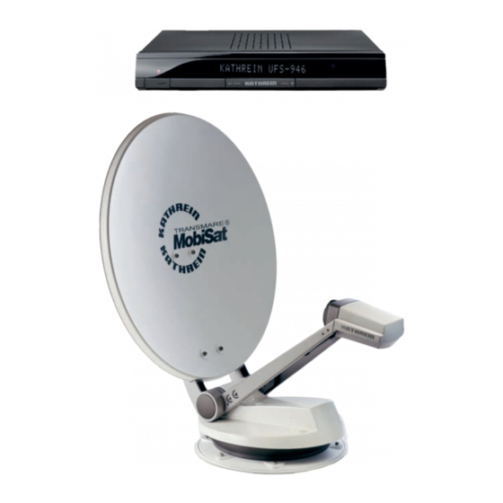
MobiSet 4 CAP 920 components / scope of delivery 75 cm satellite dish Twin LNB Turntable with integral con- trols and GPS receiver UFS 946/CI+ (front view) See the UFS 946/CI+ oper- ating manual for a rear view of the receiver together with an explanation of functions and operating instructions. -
Page 4: Table Of Contents
Contents Installation Manual General ........................2 MobiSet 4 CAP 920 components / scope of delivery ........3 Proper Use ......................6 Proper use (use for the intended purpose)................6 Safety Instructions – Important Notes ...............7 Installation and connection ................10 Required tools and equipment ..................10 Unpacking and Preparation ....................10... - Page 5 Operating Manual Important information for CAP 920 before setup ...........40 First installation ....................41 CAP menu (polar antenna settings) ..............46 15.1 Calling up the CAP menu ....................46 15.2 Move CAP to park position ....................46 15.3 Resetting the CAP system (polar antenna) (RESET) ............46 15.4 CAP settings (main menu) ....................47 Alignment (satellite search) ................48 Channel (satellite) selection ................49...
-
Page 6: Proper Use
Proper Use Proper use (use for the intended purpose) The MobiSet 4 CAP 920 is designed to receive digital TV and radio programs via satellite. The automatic positioner is intended to be used as a turntable for the Kathrein satellite dish. -
Page 7: Safety Instructions - Important Notes
Safety Instructions – Important Notes Safety during installation work Warning Risk of injury or even death through installation work in places with a risk of falling and from falling parts. Please note the following safety points: ● Use a working platform. ●... - Page 8 Safety Instructions – Important Notes Road Traffic Licensing Regulations (StVZO) The applicable regulations of the German StVZO must be observed in respect of fixed installation of the turn- table on a vehicle which is driven on public highways. In particular, Articles 19/2; 30 C; 32 (2) and EC directive 74/483 EEC are applicable. Briefly, they state that no endorsement of the vehicle documentation is required unless the antenna unit causes the height of the laden vehicle to exceed 2 m, or the antenna unit projects beyond the outer lat- eral outline of the vehicle. The maximum permissible height of 4 m (vehicle and antenna unit) may not be exceeded.
- Page 9 cannot be disconnected by intermediate switches, as this could deactivate the automatic lowering function. Important The antenna is lowered approx. 5 seconds after the ignition circuit is turned on!. Precondi- tions: The TV set is in standby mode, the receiver has been switched off, the power supply to the turntable has not been cut off. Otherwise the control unit that is in use is lowered immediately. Lowering the antenna can take up to 30 seconds (after the ignition is switched on)! Checks before commencing a journey...
-
Page 10: Installation And Connection
Installation and connection Required tools and equipment ● Circular cutter, Ø 38 mm ● Flat-bladed screwdriver for M5 screws ● power drill ● Galvanised round head screws, depending on the roof structure (Ø: 5 mm, self-tapping screws D 7981, depending on roof panel structure) or round head screws D 7985 with shims and nuts ●... -
Page 11: Selecting The Installation Location
Selecting the Installation Location Essentially, the cable lengths of the MobiSet 4 CAP 920 components allow you a free choice of installation location on your caravan or motor home. However, you should take note of the following points: ● Before installation, you should find out whether the operating manual for your vehicle permits the fitting of non-vehicle-specific parts or what requirements need to be met in order to do so. -
Page 12: Installation Steps
5.4.1 Installation of the cable gland and mounting plate Note If you had previously used a Kathrein HDM 140/141 jointed tripod mast or another mast with a diameter of 34 mm, you can continue using the existing through hole in the roof (if space allows). ● In the centre of the intended position of the turntable, drill the opening for the cable gland with a circular cutter (Ø 38 mm). Deburr the hole with a round file or emery paper. - Page 13 ● If the roof panel material is very thin and does not provide adequate holding power within the insulation material , through holes (Ø 5,5 mm) into the interior of the vehicle are required and galvanised M5 round head screws of sufficient length must be used. Make sure that you use a sufficiently strong support that can withstand the bolt tensile forces (large plain washer or a complete reinforcing plate).
- Page 14 Installation and connection ● Apply the adhesive sealant evenly to the underside of the mounting plate, completely covering the area within the circular groove (Fig. D). This area of the vehicle roof must be completely coated with adhesive in order to achieve the necessary bonding force.
- Page 15 plate. ● Allow the turntable to rest on the front edge of the mounting plate. Keep the turntable supported at an angle (see Fig. E1) and insert a suitable piece of wood underneath it. ● Now lay and connect the turntable cables in the mounting plate (as indicated on the mounting plate, see Fig. E1). Take particular care that the two master coaxial cables, marked red, are connected to each other. Initially tighten the coaxial cable plugs finger-tight, using no tools, then tighten them lightly using an open-ended 11 AF spanner.
- Page 16 Installation and connection ● To prevent water vapour from inside the vehicle reaching the turntable through the roof gland, thread the three cables through the sealing gasket supplied (see Fig. E2), close the gasket and insert it into the roof gland until it reaches the stop.
- Page 17 Figure: F1 Master coaxial cable (marked red) Figure: F2 (220) (450) ① When using a cable duct as a direct extension of the cable exit from the CAP, its height must not exceed that of the cable feed system hood, i.e. 10 mm. ② Cables laid in the cable duct ③ Roof gland HDZ 100, not included 17 from 56...
-
Page 18: Brief Instructions For Installing The Turntable
Brief instructions for installing the turntable Note The sequence of pictures shown illustrates all the necessary installation steps that are required to install the turntable and the preassembled parabolic reflector on the roof of the vehicle. The other detailed instructions in this installation and operating manual must also be followed! 2. Apply Sikaflex ® 1. Montageort festlegen. 291i adhesive to the spigot of the roof duct. Insert the spigot into the hole and secure it from below with the knurled nut. - Page 19 5. Align the mounting plate with the arrow in the Caution direction of travel. The arrow is marked with Risk of injury. Avoid skin contact an ① at step 8 in the illustration. with the adhesive! 6. Mark out the six holes to secure the mounting 7. Apply Sikaflex ® 291i adhesive in a wavy line plate.
-
Page 20: Installation Of The Ufs 946/Ci
Installation and connection Installation of the UFS 946/CI+ 5.6.1 Selection of a suitable installation location Note When choosing the installation location, bear in mind that the rear of the unit should always be accessible. The UFS 946/CI+ is equipped with a power saving circuit and a separate infrared transmitter, which means that the unit does not need to be placed where it is visible. You can therefore fit the UFS 946/CI+ out of sight in any location, e.g. - Page 21 Connections and fusing of the unit All connection cables for connection to the receiver (including the infra-red sensor) are connected at the rear of the unit (see also “Connection example” in this section). When selecting the installation location, allow suf- ficient clearance at the rear of the unit for these cables and their plugs. On the left hand side of the receiver viewed from the front there is a fuse inserted from the outside. This fuse (for the type, see the section “Important Information” in the receiver operating manual) should be accessible even after the unit has been installed, so that it can easily be exchanged if required. 5.6.2 Preparations Attaching the infrared sensor You can attach the infra-red sensor directly to the unit; or if the receiver is installed in a concealed location, you should position the infra-red sensor where it can be clearly seen by the remote control unit.
- Page 22 Installation and connection 5.6.4 Suspended installation Remove the wood screws supplied from their transport attachment on the top of the respective mounting piece (2 pieces). Place the two mounting pieces on your receiver as shown in Figures 1–3. During the process the following should be taken into account: Left (L) and Right (R) markings (see...
- Page 23 Installation on a fixed flat surface 5.6.5 So as to prevent the receiver slipping or falling, the installation kit can also be attached to the under- side of the receiver. Assembly is the same as for suspended installation, except that the mounting kit is attached to the underside of the receiver. 5.6.6 Laying the cables and connecting the turntable • Lay the master coaxial cable (marked red) to the UFS 946/CI+ and the second coaxial cable to the sec-...
- Page 24 Installation and connection Warning Danger of cable fires. Never bypass the fuses in the cable and in the receiver ● At the connecting point for the power cable, the voltage must not fall below 11.5 V even with a load of 12 A. Otherwise optimum functioning can no longer be guaranteed. ● Connect the power cable to the respective socket in your motor home or caravan (12 V or 230 V). Only for connection in a motor home, not in a caravan! ● The third, green connecting cable, marked “IGNITION” allows you the option of connection to a circuit in the vehicle that is activated when the ignition key is turned and then carries a continuous 12 V supply. This type of connection ensures that when the engine is started the antenna is automatically lowered into the park position (the receiver does not need to be turned on).
- Page 25 Connection example for 12 V battery connection 5.6.9 Figure: G Important For operation with two batteries, it is necessary to ensure that the ignition signal earth has the same potential as the power supply bat- tery earth for the turntable. Non- compliance means that the auto- matic lowering function will not work! Ensure the cable polarity is correct!
-
Page 26: Reception Range / Footprint
Reception range / footprint The footprint is the reception area on the earth that a satellite covers with its transmission beam (spot), within which satellite reception is possible. The transmission power is at its greatest in the centre of this spot – it becomes progressively weaker moving outwards. -
Page 27: Dismantling For Servicing
The enclosure is then watertight once again. Address of the service centre Factory repair centre Regional repair centre Katek Service GmbH KATHREIN Sachsen GmbH Philipsstrasse 1 Lindenstrasse 3 35576 Wetzlar 09241 Mühlau Tel.:... -
Page 28: Polarisation Setting
Polarisation setting Polarisation setting The polarisations setting is required to compensate for the so-called skew. The skew is the discrepancy between the vertical polarisation of the received signal from the geographical verticals. For optimal recep- tion the LNB must be installed before the satellite disk, inclined by the skew angle. The CAP 920 calculates the skew angle on the basis of the GPS data and inclines the LNB fully automati- cally. -
Page 29: Manual Retraction
Manual Retraction 1. In the centre of the axis (arrowed) there is a plastic cap. Lever this off with a narrow slot-head screwdriver. 2. Behind the cap is an M8 hexagon head screw. Unscrew these using a 13 mm socket wrench. After removing the M8 screw, another thread can be seen. -
Page 30: Technical Specifications
Technical Specifications Type Unit CAP 920 Order no. 20310029 Diameter parabolic reflector approx. 2 switchable outputs: V/H (14/18 V) Low/High (0/22 kHz) Supply voltage LNB Vertical: 11.5 – 14 Horizontal: 16 – 19 Input frequency 10.70 – 12.75 Output frequency 950 – 1950 / 1100 – 2150 Oscillator frequency (L. O.) 9.75/10.60 Performance at 11.3/12.5 GHz... - Page 31 Dimensions Fahrtrichtung / driving direction / sens de la marche 512 mm 981 mm 446 mm 512 mm 738 mm 31 from 56...
-
Page 32: Sikaflex ® -291I - Safety Data Sheet
Sikaflex ® -291i – Safety Data Sheet Safety Data Sheet Conforms to Regulation (EC) No. 1907/2006 (REACH), Annex II - United Kingdom (UK) IDENTIFICATION OF THE SUBSTANCE/PREPARATION AND OF THE COMPANY/UNDERTAKING Identification of the substance/preparation Product name or Trade name : Sikaflex®-291i Use of the substance/preparation Chemical product for construction and industry... - Page 33 Sikaflex®-291i 02.12.2010 2/5 FIRE-FIGHTING MEASURES Extinguishing media Suitable Use an extinguishing agent suitable for the surrounding fire. Not suitable None known. Special exposure hazards In a fire or if heated, a pressure increase will occur and the container may burst. Hazardous combustion Decomposition products may include the following materials: products...
- Page 34 Sikaflex ® -291i – Safety Data Sheet Sikaflex®-291i 02.12.2010 3/5 EXPOSURE CONTROLS/PERSONAL PROTECTION Ingredient name Occupational exposure limits No exposure limit value known. Recommended monitoring If this product contains ingredients with exposure limits, personal, workplace procedures atmosphere or biological monitoring may be required to determine the effectiveness of the ventilation or other control measures and/or the necessity to use respiratory protective equipment.
- Page 35 Sikaflex®-291i 02.12.2010 4/5 TOXICOLOGICAL INFORMATION Potential acute health effects Inhalation : May cause irritation. Ingestion Can cause gastrointestinal disturbances. Skin contact : May cause skin irritation. Eye contact May cause eye irritation. Chronic effects No known significant effects or critical hazards. ECOLOGICAL INFORMATION Environmental effects : Avoid contact of spilt material and runoff with soil and surface waterways.
-
Page 36: Regulatory Information
Sikaflex ® -291i – Safety Data Sheet Sikaflex®-291i 02.12.2010 5/5 REGULATORY INFORMATION EU regulations Classification and labeling have been determined according to EU Directives 67/548/EEC and 1999/45/EC (including amendments) and take into account the intended product use. Additional warning phrases : Contains isocyanates. See information supplied by the manufacturer. Contains Sika Hardener LH (1,6-Hexanedialdimine), Pentamethyl piperidylsebacate. -
Page 37: Sikaflex ® 291I - Product Data Sheet
Sikaflex ® 291i – Product Data Sheet Product Data Sheet Version 3 (09 / 2011) ® Sikaflex -291i Multifunctional adhesive sealant for marine application Technical Product Data Chemical base 1-C polyurethane White, grey, black, Colour (CQP 001-1) brown Cure mechanism Moisture-curing Density (uncured) (CQP 006-4) (depending on colour) 1.3 kg/l approx. - Page 38 Sikaflex ® -291i – Product Data Sheet Cure Mechanism Packaging Information Do not apply at temperatures below 10°C or above 40°C. The ® Sikaflex -291i cures by reaction Tube 100 ml optimum temperature for substrate with atmospheric moisture. At low Cartridge 300 ml and sealant is between 15°C and...
- Page 39 The Kathrein Technical Customer Support is also at your disposal. Tel.: 08031/184/-700 Note The EPG data for the currently selected channel is updated automatically in the background while you are watching a TV channel.
-
Page 40: Important Information For Cap 920 Before Setup
Important information for CAP 920 before setup Warning In the following operating manual we assume that the UFS 946/CI+ and the turntable have been properly installed and connected, as described in the installation and operating manuals. If you have not yet done so, read the safety instructions at the beginning of the UFS 946/CI+ operating manual and follow them when handling the UFS 946/CI+ and the turntable! Important... -
Page 41: First Installation
First installation Warning ● Before using your unit for the first time, read the “Safety Instructions – Important Infor- mation” and “Installation and Connection” sections. ● You will find a sample configuration for a motor home in the Section "Installation and connection", "Connection Example". ● Do not connect the unit to the power supply until all installation work has been prop- erly carried out. ● The guidance given in the “First Installation” section assumes that the receiver has been properly connected, as per the “Safety Instructions – Important Information” and “Installation and Connection” sections. - Page 42 First installation (green) button to move to the next menu. Press the The following on-screen display appears: Use the buttons to make the basic settings for the video and audio output of the receiver to the TV set. For this, refer to the operating instructions for your TV set and take care to select only those settings that your TV set can process.
- Page 43 Show 4:3 Event Here you can select the type of screen display mode for 4:3 broadcasts on a 16:9 TV set. Either - Normal (Pillarbox) - Stretched (Full Screen) or - Zoomed in (Pan & Scan) Audio Format via HDMI Here you can select the type of audio signal that is transmitted by the HDMI interface. Select the signal that your TV set can process: - PCM (Stereo) or - S/PDIF format (multichannel)
- Page 44 First installation (green) button to move to the next menu. Press the The following on-screen display appears: button to confirm. During the image display the following message is displayed: Press the After a successful initialisation the following message appears: 44 from 56...
- Page 45 (green) button to move to the next menu. The following on-screen display appears: Press the The program list is preinstalled, it is not absolutely necessary to run the channel search (Run chan- nel search = No). (green) button to move to the next menu. The message at the bottom left appears, and then Press the the following at the bottom right: Set Local Time Here you can use the buttons to select the local time offset to UTC (formerly GMT) (e.g.
-
Page 46: Cap Menu (Polar Antenna Settings)
CAP menu (polar antenna settings) 15.1 Calling up the CAP menu (green button). One of the following illustrations will be displayed: Press You can make further CAP settings from the main menu under “Settings”, “Antenna & Satellite”, “Tuner Con- figuration”, “Tuner 1” (CAP), “CAP settings”. 15.2 Move CAP to park position Press the (green) button, select with the buttons "Move CAP to park position" and press . -
Page 47: Cap Settings (Main Menu)
15.4 CAP settings (main menu) You can make further CAP settings from the main menu under "Settings", "Antenna & Sat- ellite", "Tuner Configuration", "Tuner 1" (CAP), "CAP settings" (illustration below). Important Important basic settings for the CAP can be made in the "CAP settings" menu. These settings should be performed by a specialist to match your particular needs and the conditions; if they are set incorrectly the CAP could be damaged. -
Page 48: Alignment (Satellite Search)
Alignment (satellite search) The antenna is aligned automatically. After the UFS 946/CI+has been switched on, the turntable automati- cally moves to the last channel received and the associated satellite position (e.g. ARD/ASTRA). This works because each satellite is automatically recognised by the turntable. The satellite search is started when you select a channel. -
Page 49: Channel (Satellite) Selection
Channel (satellite) selection By pressing the buttons all the channels can be selected in the sequence that they appear in the current channel list and its sorting. Press the (blue) button to switch between TV and radio channels. 17.1 Channel selection from the channel list ... -
Page 50: Channel Selection From The Channel List (Sorted By Satellite)
channel. The selection of the desired channel is confirmed by pressing the button. As soon as the turn- table has found the satellite or has reached the known position, you will now hear and view the currently selected channel in the small window at the top right. To exit the channel list and return to the TV picture, press the button again, or press the button. Note A comprehensive explanation of the channel list with its detailed functions (e.g. the scan and sort function) can be found in the UFS 946/CI+ operating manual. -
Page 51: Change Of Location
Change of location The turntable automatically recognises a change of location through the built-in GPS receiver . After a minor change of location the turntable moves to the last selected position and so quickly finds the satellite again. After a more major change of location the turntable looks for the satellite on the basis of the GPS data of the new location The following message appears while the turntable is moving: As soon as the turntable has found the right satellite it saves its position so that it can find it more... -
Page 52: Special Messages From The Turntable
Special messages from the turntable 20.1 System protection messages 20.1.1 Undervoltage The following messages are shown on the screen to protect your reception system and the on-board power supply: The power supply to the turntable is inadequate (battery voltage below the minimum value). This message means that the turntable can still be operated. -
Page 53: Further Messages
Obstruction in the swing path 20.1.3 The motorised antenna has reached the mechanical stop or is jammed! If the unit encounters an obstruc- tion, the CAP reverses 10°. This allows the obstruc- tion to be removed more easily. Check whether the turntable is obstructed (e.g. by a branch). Overtemperature of the rotation motor 20.1.4 The turntable motor temperature is in the critical range. -
Page 54: Declaration Of Conformity
Declaration of Conformity 54 from 56... -
Page 55: Disposal Instructions
Disposal Instructions Electronic equipment is not domestic waste - in accordance with directive 2002/96/EC OF THE EUROPEAN PARLIAMENT AND THE COUNCIL dated 27th January 2003 concerning used electrical and electronic appliances, it must be disposed of properly. At the end of its service life, take this receiver for disposal at a designated public collection point. - Page 56 936.4731/a/VMWI/1214/GB – Technical data subject to change! Internet: www.kathrein.com KATHREIN-Werke KG • Anton-Kathrein-Strasse 1–3 • Postfach 10 04 44 • 83004 Rosenheim • Germany • Phone +49 (0) 8031 184-0 • Fax +49 (0) 8031 184-385...
Need help?
Do you have a question about the MobiSet 4 CAP 920 and is the answer not in the manual?
Questions and answers