Kathrein UFD 540 Operating Manual
Dvb caravan receiver
Hide thumbs
Also See for UFD 540:
- Instructions de montage manual (22 pages) ,
- Mode d'emploi (80 pages)
Table of Contents
Advertisement
Quick Links
Advertisement
Table of Contents

Related Manuals for Kathrein UFD 540


Summary of Contents for Kathrein UFD 540
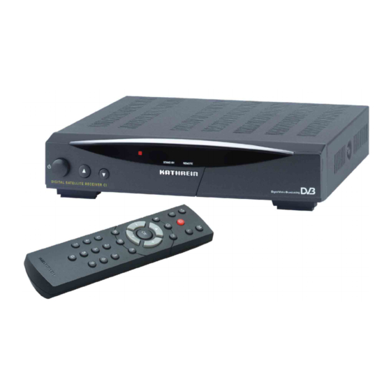
- Page 1 Operating manual DVB Caravan Receiver UFD 540 Order no.: 260 515...
-
Page 3: Preface
We are always trying to adjust the software to the de- sires of our customers and the state-of-the-art technology. Refer to section "Software and channel lists update" for more information. ® ® micro and UFO mini are registered trademarks of the KATHREIN Werke KG. DiSEqC™ is a trademark of Eutelsat. -
Page 4: Table Of Contents
Contents Contents Preface...3 Contents ...4 Safety Instructions ...7 Control Elements, Displays and Connections...8 View of front panel ... 8 View of rear panel... 8 Front panel control elements and Rear panel control elements and Remote control handset buttons... 9 Command of Remote Control...10 Operating Instructions ...11 Menu concept ... - Page 5 Contents AC3 ... 31 Switching off sound ... 31 Channel list ...32 Selecting programmes last received ... 32 Favourite programmes... 32 Search programmes alphabetically ... 37 Sorting programmes ... 38 Deleting programmes ... 39 Manually adding programmes ... 40 Adding and Removing Satellites...42 Setting up satellites...
- Page 6 Contents Data Transfer from Receiver to Receiver ...70 Preparation ... 70 Transferring channel lists ... 70 Transferring operating software ... 70 Technical Annex ...71 Technical features ... 71 Technical data ... 72 Accessories ... 73 Scart socket assignments... 73 Switch-over VHS/S-VHS ... 73 Connection example...74 Short Technical Lexicon ...75 Glossary...
-
Page 7: Safety Instructions
Safety Instructions Safety Instructions... -
Page 8: Control Elements, Displays And Connections
Control Elements, Displays and Connections Control Elements, Displays and Connections View of front panel View of rear panel Front panel control elements and displays On/Off switch Channel buttons (up/down) Common Interface for Pay-TV cards* hind front flap, open by lightly applying pressure on the upper right-hand corner _________________________________________ CA module and Pay-TV cards are not included in delivery... -
Page 9: Remote Control Handset Buttons
Control Elements, Displays and Connections Remote control handset buttons Switch over of the remote control Calls up the last 4 programmes / favour- ite categories Programme info EPG programme guide Locks channels Channel lists Programme info Help ... -
Page 10: Command Of Remote Control
Command of Remote Control Command of Remote Control Note The remote control features 2 command sets, making it possible to operate 2 receivers independently of each other in one room (not in conjunction with a twin receiver). For this purpose, program one receiver on the command set 1 and the second receiver on the command set 2. -
Page 11: Operating Instructions
Operating Instructions Operating Instructions Menu concept Note: Observe the bar on the lower edge of the screen with functions for the re- spective menu item. Button functions The menu concept is set up in a logical operating sequence. The current selected programme always appears in the upper right- hand corner of the screen. -
Page 12: Alphanumeric Entries
Operating Instructions Alphanumeric entries is a switch-on button with menu functions. Press to exit setting. In function channel list: Locks the pro- gramme is a switch-on button with menu functions. Press the button again to exit. In function channel list: Makes a channel a favourite channel. ... -
Page 13: Alphanumeric Assignments Of Number Buttons On The Remote Control
Operating Instructions Alphanumeric assignments of number buttons on the remote control Button Language selection- OSD To select the language for the on-screen menus press: The available languages are German, English, French, Italian, Spanish, Portuguese, Dutch, and Turkish. -
Page 14: Connection And Start-Up
Connection and Start-up Connection and Start-up Connecting receiver Sat-IF connection Preconditions for receiving signals Presetting of receiving system The following section is specifically intended for the specialist dealer. You only need to read this section, if you are carrying out the installa- tion yourself. -
Page 15: Lnb Supply Voltage
Connection and Start-up LNB supply voltage TV and video recorder connection Audio connection Dolby connection Inserting batteries in the remote control If the feed system (LNB) is powered by an external supply voltage and the LNB supply voltage is not used for switching polarity, the LNB supply of the receiver must be set to "OFF"... -
Page 16: First Time Installation
First Time Installation First Time Installation The first steps Factory setting of receiver Connect the receiver to the mains power supply. Switch on the receiver by pressing the power button on the front of the unit. The display, "- - - -,“ appears in the LED display. When the LED for the operating display is red, the television is in standby. -
Page 17: On Screen Displays / Osd
On Screen Displays / OSD On Screen Displays / OSD Important screen displays Help function The receiver functions are controlled by a microprocessor and an ex- tensive software. The following explanations are intended to improve your understanding of all procedures and to minimise the risk of mis- takes. -
Page 18: Tv Channel Identifier
On Screen Displays / OSD TV channel identifier Radio channel identifier Error message With the button, exit the help function and return to the main menu. Press the button again and return to the originally received programme. The channel identifier is displayed for several seconds every time the channel is changed or by pressing the that a channel is received even if no picture can be seen (e.g. -
Page 19: Channel List - Radio/Tv
On Screen Displays / OSD Channel List – Radio/TV Press button A + for the main channel list is indicated at the top left. Information about the channel, programme provider, and whether the programme is normally encrypted is found underneath. The upper-right column contains information about the received satellite, the transponder, and its frequency as well as the polarisation. -
Page 20: Videotext
Videotext Videotext This symbol in the programme display indicates, whether teletext is transmitted with the called up programme By pressing the 0 button, the receiver prepares the teletext –also for scrambled signals- for the television set. The following display appears for a short time. During the search, the programme page (here P100), which is being searched for, is displayed in the upper left-hand corner and the run- ning time is displayed in the upper right-hand corner. -
Page 21: Programme Selection
Press the button once more and the display disappears. You will receive the "channel scrambled" message for scrambled channels. You can receive these programmes with the UFD 540 only with CA module and card. buttons in order to select other... - Page 22 Programme Selection A further option for selecting a different programme is to press the button. The TV channel list is now displayed. The upper right- hand column provides information relating to the received satellites, the transponder and its transmission frequency, polarisation, the sym- bol rate and the scrambling.
-
Page 23: Selecting A Tv Programme By Number Entry
Programme Selection Selecting a TV programme by number entry Example Switch-over to a radio programme Reception status - radio You can select a different TV programme during a running TV pro- gramme by entering the programme location number. Use the num- ... -
Page 24: Selecting A Radio Programme By Number Entry
Programme Selection Selecting a radio programme by number entry Example button. The radio channel list is now displayed. The upper right- hand column provides information relating to the received satellites, its transmission frequency, the polarisation, the symbol, rate, the bouquet and the scrambling. -
Page 25: Common Interface
Common Interface Common Interface Observe the operating manual of your Pay-TV provider. The Common Interface for the insertion of two so-called Conditional Access Modules is located underneath the front flap. The purchasable Smartcard from the Pay-TV provider, which is suited to a particular encryption technology, is inserted into the CA module. - Page 26 Common Interface However, a CA module must be available. You can find which card is located in the Common Access Module via the main menu and the menu „Common Interface.” Confirm selection by pressing Via the main menu item „Common Interface“ and by pressing , the display appears (each according to the CA-module and card version): The following displays depend on the module and the card and...
- Page 27 Common Interface Always pay attention to the instructions from your Pay-TV pro- vider! Here, select the submenu “Common Interface” with the but- tons and confirm selection by pressing Note for the Conax-, SECA-, Viaccess and CryptoWorks user: Please observe, that the programme providers carry out the clearing of pay-TV cards by different monthly release intervals.
-
Page 28: Timer Settings
Timer Settings Timer Settings You can use the timer for recording a programme on time with a video recorder. 14 timers are available which you can be set to different programmes as well as start and end times. to enter the main programme menu, In the timer setting, press ... -
Page 29: Vps Signal
Timer Settings VPS signal Confirm the settings by pressing If you have pre-programmed a download per timer, all following timer settings will be ignored after a successful download! Make certain, that no VPS signal is included in the digital television signal. -
Page 30: Sound Settings
Sound Settings Sound Settings Volume setting Stereo and two-channel sound reproduction Set the required volume level by pressing the mote control of the receiver. A bar indicator is displayed on the screen to show the set volume. The channel identifier, which is displayed by pressing the shows the set sound reproduction. -
Page 31: Ac3
Sound Settings Switching off sound The receiver has an audio output for the AC3 format (Dolby Digital) providing you with the opportunity of listening to cinema sound quality in your living room. Only connect the digital output with a correspond- ing system. -
Page 32: Channel List
Channel list Channel list Selecting programmes last received Favourite programmes The programme/channel settings set at the factory can be changed in the menu, “Channel list." Access the menu by pressing the ton, the buttons as well as selection with . - Page 33 Channel list With the buttons select the desired programme, which will be highlighted with a coloured bar. The bar can be shifted page-by-page or line-by-line with the cursor buttons. You can also enter the desired programme number with the numerical buttons.
- Page 34 Channel list Press the button to access the channel list, and with the but- ton you can access the favourite list. Use the buttons to select a favourite programme. It is then highlighted by a coloured bar. ...
- Page 35 Channel list After finishing the letter entry, confirm it by pressing to the channel list. Press to return to the television screen. Your changes are saved and confirmed, and an info display of the current received programme appears for a few second on the screen. In order to call up a favourite programme, access the respective de- sired favourite list after pressing the First, select the line with the "apple"...
- Page 36 Channel list With the buttons, select your desired programme, which is highlighted with a coloured bar and displayed in the upper right-hand corner of the screen. By pressing the button, your selected fa- vourite programme appears. If you want to delete a marking, with the buttons and select the favourite list, in which the desired programme is saved, and...
-
Page 37: Search Programmes Alphabetically
Channel list Search programmes alphabetically buttons, select "all satellites." Press rent channel list. Receive an overview of programmes with the same initials in a list. With this, it is possible to quickly find a certain programme from the entire channel list. ... -
Page 38: Sorting Programmes
Channel list Sorting programmes phabet" bar. Press to confirm the selected letters and a list of all the pro- grammes appears, which begin with the selected letters. With the buttons, you can now choose the desired channel, which is then highlighted with a coloured bar. The channel preview appears in the upper right-hand corner of the screen. -
Page 39: Deleting Programmes
Channel list Deleting programmes Be careful when delet- ing programmes! With the button, you "hold" the programme which is to be moved, It will be highlighted with a different coloured bar. You can now move it to the desired position using the ... -
Page 40: Manually Adding Programmes
Channel list Manually adding programmes Attention: You can only call up satellites which are included in the installation menu. Basically, follow the same procedure for sorting in order to add a channel. With main menu button , access the channel list. ... - Page 41 Channel list By pressing , you return to the channel list. The saving of the change is confirmed and the info display of the current set programme appears for a few second on the screen. The new programme is added to the existing channel list.
-
Page 42: Adding And Removing Satellites
Adding and Removing Satellites Adding and Removing Satellites Setting up satellites Naturally, the LNB can also accommodate new satellites. In order to do so, the orbit position, which you need to take a bearing on, must be known. The “Antenna settings“ menu entry in the installa- tion menu can be used as an aid for aligning the antenna. -
Page 43: Entering Satellite Names
Adding and Removing Satellites Entering satellite names Removing satellites After pressing the button, you are asked if you want to add the satellites. . Confirm it with The following message appears You can now make the respective entries to your receiving system in the corresponding positions using the ... -
Page 44: Programme Overview
Programme Overview Programme Overview With the EPG button , you receive an overview of the programmes currently received from the transponder with time and duration (see on-screen display), provided that they are broadcast with electronic programme guide (EPG), for example, with ARD and ZDF. In the right- hand column, the programme title is given in abbreviated form. -
Page 45: Epg Timer Programming
Programme Overview EPG timer programming With the EPG button view of the currently received broadcaster with time and duration (see on-screen display), provided that they broadcast the electronic pro- gramme guide (EPG). The length of the channel list depends on each programme provider and can cover several days. - Page 46 Programme Overview Confirm the selection with . The confirmation appears for a few seconds. The programme will be recorded at the set time. Press two times to leave this position without a timer setting. ...
-
Page 47: Password
Password Password Factory setting Entering a password You can prevent your satellite receiver to be used by unauthorised persons by means of a password. With this password, you can en- sure your reception settings are not changed by others. At the same time, you can activate the parental control function to lock out various programmes. - Page 48 See section "Operating instructions" for information on how to use the numerical buttons on the remote control for alphanumerical entry. The factory setting is „UFD 540“. You have now undertaken all the settings for safeguarding and identi- fying your satellite receiver.
-
Page 49: Parental Lock
Password Parental lock You can set the parental lock in a manner similar to that used for marking favourite programmes with the "Apple" symbol. This denies children access to unsuitable programmes. The "Padlock" symbol is used to identify the programmes in the "TV" or "radio" channel lists. ... - Page 50 Password After calling up the locked programme with the number keys, the mes- sage, "This programme is locked" appears and the programme can not be seen. After pressing and calling up a locked programme over the chan- nel list, you will be asked to enter in your password in order to watch the locked programme.
-
Page 51: Operation From Front Panel
Operation from Front Panel Operation from Front Panel Backup operation If you have misplaced the remote control or the batteries are empty, you can still operate you receiver from the front panel. On the front panel, there are 3 buttons at your disposal. The On/Off button as well as two channel buttons. -
Page 52: Setting System Parameters
Setting System Parameters Setting System Parameters The following settings should not be altered without good reason, since they are factory settings or operational settings, matched spe- cifically to your receiving system. Only extensions to the receiving systems or modifications call for new settings. -
Page 53: System Parameters
Setting System Parameters System parameters Parental lock System information Select the menu „System parameters“ with the buttons in the main menu and tons and , you can call up other positions. The basic settings that can be implemented here are described under setting parental lock in chapter "Password."... -
Page 54: Local Time/Timer
Setting System Parameters Local time/Timer TV type Picture format Screen A/V mode The receiver displays the UTC time transmitted with the data stream (United Time Coordinate, former Greenwich Mean Time). Therefore, in Germany, the time must be corrected by +1 hour. If necessary, the summer time must be corrected, in order for the tim- ers to turn on and off at correct times. -
Page 55: Installation Menu
Setting System Parameters Installation menu LNB configuration Oscillator frequency L.O. /synchronising-signal) • RGB – red-/green-/blue-signal • Y/C – S-VHS signal (luminance/chrominance). Confirm by pressing two times. You should not change the following settings without good reason as they represent factory settings or operational settings that are adapted to your receiving system. -
Page 56: Changing The Oscillator Frequency
Setting System Parameters Changing the oscillator frequency Operation Standby Reception of two satellites The satellite transmission frequencies are within the following ranges: 10.7…11.7 GHz Low-band ( Low-band / analogue transmission) 11.7…12.75 GHz High-band (High-band / digital transmission) (valid for ASTRA satellites at 19,2° E) The reception frequency of the receiver, however, is in the range from 950 to 2150 MHz. -
Page 57: Diseqc Setting
Setting System Parameters Different control signals are required for the purpose of selecting the satellite signals. To date, the LNB supply voltages 14/18 V and the 22 kHz signal (superimposed on the LNB supply voltage) have been suf- ficient for signal selection in the majority of applications. With these four switching signals, it is possible to switch between horizontally and vertically polarised signals as well as between satellites (multifeed re- ception). -
Page 58: Antenna Settings
Setting System Parameters Antenna settings Antenna rotor / Positioner (DiSEqC 1.2) This menu is intended solely for service purposes and, if need be, i.e. if no measuring instrument is available, it can be used to align the an- tenna (satellite dish). The satellite can be defined in the first line and the transponder in the second. -
Page 59: Satellite Search
Setting System Parameters Satellite search The receiver allows you to search for programmes on a satellite in the menu ‘Satellite search.’ With the menu line. In the first line, select if only free-to-air receivable pro- grammes or free-to-air and scrambled programmes should be ... -
Page 60: Tp Set-Up/Search
Setting System Parameters TP set-up/search All programmes are added to the existing channel list and highlighted with a different colour You can cancel the search by pressing the In this menu, you can scan through the transponders for specific pro- grammes, e.g. -
Page 61: Transponder Selection
Setting System Parameters Transponder selection The following settings are now possible (select positions with • desired satellite with • the transponder frequency with • the polarisation with button, • the symbol rate with the numerical buttons and •... - Page 62 Setting System Parameters Exit this menu by pressing and skip to the previously highlighted programme. With the button, return to this menu once more to search for fur- ther transponders. After an unsuccessful search, the following message appears: Error All new programmes are added to the existing channel list.
-
Page 63: Diseqc [Ufo] Set-Up
Setting System Parameters DiSEqC [UFO] Set-up 22 kHz signal Tone burst and DiSEqC signal You should only make changes in this menu, when the receiver is connected to another receiving system with different features or if changes have been made to the receiving system. Pay close attention to the instructions of your Sat IF system. -
Page 64: Tone Burst
The setting under this menu point is also designed for operation of the receiver together with a processing system. Control and communication between the receiver and the Kathrein UFO micro system occur via the return path of the coaxial cable. ‘ON’... -
Page 65: Factory Setting
Setting System Parameters Factory setting receiver to the receiving system for signal selection, are also recog- nised by this system. A remote frequency must not be set in this operating mode, because it is defined by the UFO micro system as part of the addressing pro- cedure. -
Page 66: Automatic Antenna Alignment With Hdp 170
Automatic Antenna Alignment with HDP 170 Automatic Antenna Alignment with HDP 170 If the automatic positioner HDP 170 is installed in your mobile home or caravan, it can be aligned via the main menu „Automatic antenna HDP.“ Also, refer to the operating manual of the HDP 170. You can switch the positioner on and off in the main menu. -
Page 67: Software And Channel List Update
Software and Channel list Update Software and Channel list Update Thanks to digital technology, the software and channel list of your re- ceiver can also be updated via satellite. Find out if a new software or channel list is available under the submenu software download. Your satellite receiving system must be aligned to ASTRA 19.2°... - Page 68 Software and Channel list Update The light cursor bar in "Software download" can be moved with the buttons. Press in the menu item "Display info" to re- ceive information about the transmitted software and channel list. The menu items "Info text," "channel list" and "operating software" are automatically set to "Yes,"...
- Page 69 „Please wait" Observe the on-screen displays! After a software update, you must set the time again! The updates are also available in the internet under the address: www.esc-kathrein.de/download/ufd/. Here, you will also find instructions for downloading.
-
Page 70: Data Transfer From Receiver To Receiver
Data Transfer from Receiver to Receiver Data Transfer from Receiver to Receiver Preparation Transferring channel lists Transferring operating software Your receiver is able to receive the RS232C socket data from another receiver. Here, both receivers must be connected via a so-called 'zero modem cable.' The transmitting receiver is in this case the mas- ter and the receiving receiver is the slave. -
Page 71: Technical Annex
Technical Annex Technical Annex Technical features The receiver UFD 540 is equipped with the following features: Reception of all DVB radio and TV programmes (Free to Air Receiver) Common Interface for two CA modules (not included in delivery) Software download via satellite and PC... -
Page 72: Technical Data
Technical Annex Technical data RF features Sat-IF frequency range Input level range IF frequency Receiving threshold (Eb/No dig.) Sat-IF input Input impedance Video Modulation, FEC, demultiplexer Video resolution Frequency range Input data rates Video decoding Bit rate Output voltage Audio Audio decoding Bit rate Frequency range... -
Page 73: Accessories
Technical Annex Accessories 1 Infrared remote control 2 Batteries 1.5 V, type: LR 03, size: AAA (Micro) 1 SCART cable 1 operating manual Scart socket assignments Signal Audio output, right Audio input, right Audio output, left Audio earth Blue earth Audio input, left Blue signal Switching voltage... -
Page 74: Connection Example
Connection example Connection example Sat-IF Scart Cinch L + R Hi-fi or Dolby digital system Connection of a DVR-S receiver on a TV set and a Hi-fi system for re- ception of digital Sat TV and radio programmes. For connection, one Scart cable and a Cinch cable are required. If your TV set is equipped for stereo, stereo sound can also be repro- duced via the stereo loudspeakers of your TV set. -
Page 75: Short Technical Lexicon
Short Technical Lexicon Short Technical Lexicon DiSEqC DiSEqC components DVB MPEG-2 Eb/No ratio Programme package Symbol rate DiSEqC (Digital Satellite Equipment Control) is a communication sys- tem between the Sat receiver (master) and the peripheral Sat compo- nents (slaves), such as LNBs, multi-switch, motorised antenna sys- tems. - Page 76 Short Technical Lexicon Transponder Video bit rate Viterbirate The symbol rate is measured in MSymbols/s and is equal to the num- ber of symbols that are received per second. A transponder is a satellite transmitter which transmits TV and radio signals.
-
Page 77: Glossary
Short Technical Lexicon Glossary Audio output Receiver sound output AV channel slot Preferential channel location of TV set for SCART input Decoder Decoder Unscrambling unit for pay-TV DiSEqC Control system between receiver and LNB, multi-switch Digital Video Broadcasting Eb/No [dB] Power density per unit of information Eb/No ratio Digital signal-to-noise ratio... - Page 78 Service OSD-Language German Satellite 1 Satellite: LO1: 9750 LO2: 10600 Satellite DiSEqC menu 22-kHz: Tone burst: DiSEqC DiSEqC repeat UFOmini Remote frequency UFOmicro Other settings Picture format 16:9 Satellite 2 Satellite: LO1: 9750 LO1: 10600 Satellite High/low PosA/B High/low PosA/B _____MHz LNB supply Operation:...
- Page 80 KATHREIN-Werke KG ž Telefon (0 80 31) 18 40 ž Fax (0 80 31) 18 43 06 Anton-Kathrein-Straße 1-3 ž Postfach 10 04 44 ž D-83004 Rosenheim...
Need help?
Do you have a question about the UFD 540 and is the answer not in the manual?
Questions and answers