Table of Contents
Advertisement
Advertisement
Chapters
Table of Contents

Related Manuals for Asus H110I-PLUS D3


Summary of Contents for Asus H110I-PLUS D3
- Page 1 H110I-PLUS D3...
- Page 2 Product warranty or service will not be extended if: (1) the product is repaired, modified or altered, unless such repair, modification of alteration is authorized in writing by ASUS; or (2) the serial number of the product is defaced or missing.
-
Page 3: Table Of Contents
Contents Safety information ..................iv About this guide ..................iv Package contents ..................vi H110I-PLUS D3 specifications summary ..........vi Chapter 1: Product introduction Before you proceed ..............1-1 Motherboard overview ..............1-2 Central Processing Unit (CPU) ........... 1-4 System memory ................1-7 Expansion slots ................ -
Page 4: Safety Information
Safety information Electrical safety • To prevent electrical shock hazard, disconnect the power cable from the electrical outlet before relocating the system. • When adding or removing devices to or from the system, ensure that the power cables for the devices are unplugged before the signal cables are connected. If possible, disconnect all power cables from the existing system before you add a device. -
Page 5: Conventions Used In This Guide
Refer to the following sources for additional information and for product and software updates. ASUS websites The ASUS website provides updated information on ASUS hardware and software products. Refer to the ASUS contact information. Optional documentation Your product package may include optional documentation, such as warranty flyers, that may have been added by your dealer. -
Page 6: Package Contents
® Supports Intel Extreme Memory Profile (XMP) Memory * Refer to www.asus.com for the Memory QVL (Qualified Vendors List). **To prevent system instability, either install DDR3L DIMMs or DDR3 DIMMs with voltage lower than 1.5V. Expansion 1 x PCI Express 3.0 x16 slot... - Page 7 - ASUS DIGI+ VRM - Stable power supply - ASUS DRAM Overcurrent Protection - Enhanced DRAM overcurrent protection - ASUS Stainless Steel Back I/O - 3x more durable corrosion-resistance for greater durability! - ESD Guards - Electrostatic discharge protection Superb Performance...
- Page 8 1 x System panel connector 1 x Chassis intrusion connector 128Mb Flash ROM, UEFI AMI BIOS, PnP, DMI3.0, WfM2.0, SM BIOS 3.0, ACPI BIOS features 5.0, Multi-language BIOS, ASUS EZ Flash 3, CrashFree BIOS 3 Drivers ASUS utilities Support DVD...
-
Page 9: Chapter 1: Product Introduction
Take note of the following precautions before you install motherboard components or change any motherboard settings. • Unplug the power cord from the wall socket before touching any component. • Before handling components, use a grounded wrist strap or touch a safely grounded object or a metal object, such as the power supply case, to avoid damaging them due to static electricity. • Before you install or remove any component, ensure that the ATX power supply is switched off or the power cord is detached from the power supply. Failure to do so may cause severe damage to the motherboard, peripherals, or components. ASUS H110I-PLUS D3... -
Page 10: Motherboard Overview
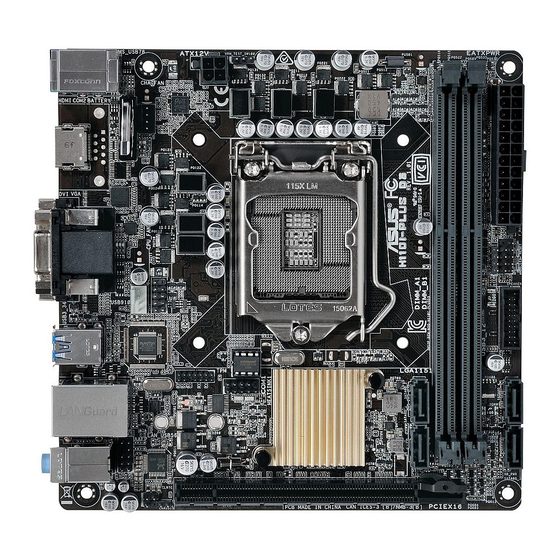
Motherboard overview Before you install the motherboard, study the configuration of your chassis to ensure that the motherboard fits. Unplug the power cord before installing or removing the motherboard. Failure to do so can cause you physical injury and damage to motherboard components. 1.2.1 Placement direction When installing the motherboard, place it into the chassis in the correct orientation. The edge with external ports goes to the rear part of the chassis as indicated in the image. 1.2.2 Screw holes Place four screws into the holes indicated by circles to secure the motherboard to the chassis. - Page 11 3. Intel LGA1151 CPU socket ® 4. DDR3 DIMM slots 5. Speaker connector (4-pin SPEAKER) 1-17 6. System panel connector (10-1 pin F_PANEL) 1-18 7. USB 3.0 connector (20-1 pin USB3_12) 1-16 8. Serial ATA 6.0 Gb/s connectors (7-pin SATA6G_1~4) 1-15 9. Serial port connector (10-1 pin COM1) 1-14 10. TPM connector (14-1 pin TPM) 1-18 11. Chassis intrusion connector (4-1 pin CHASSIS) 1-19 12. Clear RTC RAM (2-pin CLRTC) 1-11 13. Front panel audio connector (10-1 pin AAFP) 1-14 14. USB 2.0 connector (10-1 pin USB910) 1-16 ASUS H110I-PLUS D3...
-
Page 12: Central Processing Unit (Cpu)
Central Processing Unit (CPU) This motherboard comes with a surface mount LGA1151 socket designed for 6th Generation Intel Core™ i7 / i5 / i3, Pentium , and Celeron processors. ® ® ® H110I-PLUS D3 CPU socket LGA1151 Unplug all power cables before installing the CPU. • Ensure that you install the correct CPU designed for the LGA1151 socket only. DO NOT install a CPU designed for LGA1150, LGA1155 and LGA1156 sockets on the LGA1151 socket. • Upon purchase of the motherboard, ensure that the PnP cap is on the socket and the socket contacts are not bent. Contact your retailer immediately if the PnP cap is missing, or if you see any damage to the PnP cap/socket contacts/motherboard components. -
Page 13: Installing The Cpu
1.3.1 Installing the CPU ASUS H110I-PLUS D3... -
Page 14: Cpu Heatsink And Fan Assembly Installation
1.3.2 CPU heatsink and fan assembly installation Apply the Thermal Interface Material to the CPU heatsink and CPU before you install the heatsink and fan if necessary. To install the CPU heatsink and fan assembly Chapter 1: Product introduction... -
Page 15: System Memory
To uninstall the CPU heatsink and fan assembly System memory 1.4.1 Overview This motherboard comes with two Double Data Rate 3 (DDR3) Dual Inline Memory Module (DIMM) sockets. The figure illustrates the location of the DDR3 DIMM sockets: Channel Sockets Channel A DIMM_A1 Channel B DIMM_B1 H110I-PLUS D3 240-pin DDR3 DIMM sockets ASUS H110I-PLUS D3... - Page 16 Use a maximum of 3 GB system memory if you are using a 32-bit Windows OS. ® I nstall a 64-bit Windows OS if you want to install 4GB or more on the ® motherboard. F or more details, refer to the Microsoft support site at http://support.microsoft. ® com/kb/929605/en-us. • The default memory operation frequency is dependent on its Serial Presence Detect (SPD), which is the standard way of accessing information from a memory module. Under the default state, some memory modules for overclocking may operate at a lower frequency than the vendor-marked value. To operate at the vendor-marked or at a higher frequency, refer to section 2.5 Ai Tweaker menu for manual memory frequency adjustment. • Always install the DIMMs with the same CAS Latency. For an optimum compatibility, we recommend that you install memory modules of the same version or data code (D/C) from the same vendor. Check with the vendor to get the correct memory modules. Visit the ASUS website at www.asus.com for the latest QVL. Chapter 1: Product introduction...
-
Page 17: Installing A Dimm
1.4.3 Installing a DIMM To remove a DIMM ASUS H110I-PLUS D3... -
Page 18: Expansion Slots
Expansion slots In the future, you may need to install expansion cards. The following sub-sections describe the slots and the expansion cards that they support. Unplug the power cord before adding or removing expansion cards. Failure to do so may cause you physical injury and damage motherboard components. 1.5.1 Installing an expansion card To install an expansion card: Before installing the expansion card, read the documentation that came with it and make the necessary hardware settings for the card. Remove the system unit cover (if your motherboard is already installed in a chassis). -
Page 19: Headers
Headers Clear RTC RAM (2-pin CLRTC) This header allows you to clear the Real Time Clock (RTC) RAM in CMOS. You can clear the CMOS memory of date, time, and system setup parameters by erasing the CMOS RTC RAM data. The onboard button cell battery powers the RAM data in CMOS, which include system setup information such as system passwords. H110I-PLUS D3 Clear RTC RAM To erase the RTC RAM: Turn OFF the computer and unplug the power cord. Use a metal object such as a screwdriver to short the two pins. Plug the power cord and turn ON the computer. Hold down the <Del> key during the boot process and enter BIOS setup to re- enter data. • If the steps above do not help, remove the onboard battery and short the two pins again to clear the CMOS RTC RAM data. After clearing the CMOS, reinstall the battery. • You do not need to clear the RTC when the system hangs due to overclocking. For system failure due to overclocking, use the CPU Parameter Recall (C.P.R.) feature. Shut down and reboot the system, then the BIOS automatically resets parameter settings to default values. ASUS H110I-PLUS D3 1-11... -
Page 20: Connectors
Connectors 1.7.1 Rear panel connectors PS/2 mouse/keyboard combo port. This port connects to a PS/2 mouse or PS/2 keyboard. Video Graphics Adapter (VGA) port. This 15-pin port is for a VGA monitor or other VGA-compatible devices. LAN (RJ-45) port. This port allows Gigabit connection to a Local Area Network (LAN) through a network hub. LAN port LED indications Activity/Link LED Speed LED Speed Activity Link Status Description Status Description No link 10Mbps connection Orange Linked ORANGE 100Mbps connection... - Page 21 Front Speaker Out Pink (Rear panel) Mic In Mic In Bass/Center Bass/Center Lime (Front panel) Side Speaker Out To configure a 7.1-channel audio output: Use a chassis with HD audio module in the front panel to support a 7.1-channel audio output. USB 2.0 ports. These 4-pin Universal Serial Bus (USB) ports are for USB 2.0/1.1 devices. USB 3.0 ports. These 9-pin Universal Serial Bus (USB) ports are for USB 3.0 devices. • Due to the limitation of USB 3.0 controller, USB 3.0 devices can only be used under Windows OS environment and after the USB 3.0 driver installation. • We strongly recommend that you connect USB 3.0 devices to USB 3.0 ports for faster and better performance from your USB 3.0 devices. DVI-D port. This port is for any DVI-D compatible device. DVI-D can not be converted to output from RGB Signal to CRT and is not compatible with DVI-I. HDMI port. This port is for a High-Definition Multimedia Interface (HDMI) connector, and is HDCP compliant allowing playback of HD DVD, Blu-ray, and other protected content. USB 2.0 ports. These 4-pin Universal Serial Bus (USB) ports are for USB 2.0/1.1 devices. ASUS H110I-PLUS D3 1-13...
-
Page 22: Serial Port Connector/Front Panel Audio Connector
1.7.2 Internal connectors Serial port connector (10-1 pin COM1) This connector is for a serial (COM) port. Connect the serial port module cable to this connector, then install the module to a slot opening at the back of the system chassis. COM1 PIN 1 H110I-PLUS D3 Serial port (COM) connector The COM module is purchased separately. Front panel audio connector (10-1 pin AAFP) This connector is for a chassis-mounted front panel audio I/O module that supports either HD Audio or legacy AC`97 audio standard. Connect one end of the front panel audio I/O module cable to this connector. AAFP PORT2 L SENSE2_RETUR Line out_L SENSE_SEND PORT2 R... -
Page 23: Cpu And Chassis Fan Connectors (4-Pin Cpu_Fan, 4-Pin Cha_Fan)
CPU and chassis fan connectors (4-pin CPU_FAN, 4-pin CHA_FAN) Connect the fan cables to the fan connectors on the motherboard, ensuring that the black wire of each cable matches the ground pin of the connector CHA_FAN CHA FAN PWR CHA FAN IN CPU_FAN CPU FAN IN CPU FAN PWR H110I-PLUS D3 Fan connectors Do not forget to connect the fan cables to the fan connectors. Insufficient air flow inside the system may damage the motherboard components. These are not jumpers! Do not place jumper caps on the fan connectors! The CPU_FAN connector supports a CPU fan of maximum 1A (12 W) fan power. ASUS H110I-PLUS D3 1-15... -
Page 24: Usb 3.0/Usb 2.0 Connector
IntA_P2_SSTX- IntA_P1_SSTX+ IntA_P2_SSTX+ IntA_P1_D- IntA_P2_D- IntA_P1_D+ IntA_P2_D+ H110I-PLUS D3 USB3.0 front panel connector The USB 3.0 module is purchased separately. USB 2.0 connector (10-1 pin USB910) This connector is for USB 2.0 ports. Connect the USB module cable to this connector, then install the module to a slot opening at the back of the system chassis. This USB connector complies with USB 2.0 specifications and supports up to 480Mbps connection speed. -
Page 25: Atx Power/Speaker Connector
+5V Standby +5 Volts Power OK -5 Volts PIN 1 +5 Volts +5 Volts PSON# +3 Volts -12 Volts +3 Volts +3 Volts H110I-PLUS D3 ATX power connectors • For a fully configured system, we recommend that you use a power supply unit (PSU) that complies with ATX 12 V Specification 2.0 (or later version) and provides a minimum power of 350 W. • DO NOT forget to connect the 4-pin ATX +12V power plug. Otherwise, the system will not boot up. • We recommend that you use a PSU with higher power output when configuring a system with more power-consuming devices or when you intend to install additional devices. The system may become unstable or may not boot up if the power is inadequate. -
Page 26: System Panel Connector (10-1 Pin F_Panel)
System panel connector (10-1 pin F_PANEL) This connector supports several chassis-mounted functions. F_PANEL (NC) HWRST# Ground PWR_LED- HDD_LED- PWR_LED+ HDD_LED+ PIN 1 H110I-PLUS D3 System panel connector • System power LED (2-pin +PWR_LED-) This 2-pin connector is for the system power LED. Connect the chassis power LED cable to this connector. The system power LED lights up when you turn on the system power, and blinks when the system is in sleep mode. • Hard disk drive activity LED (2-pin +HDD_LED-) This 2-pin connector is for the HDD Activity LED. Connect the HDD Activity LED cable to this connector. The HD LED lights up or flashes when data is read from or written to the HDD. • ATX power button/soft-off button (2-pin PWRBTN) This connector is for the system power button. -
Page 27: Chassis Intrusion Connector (4-1 Pin Chassis)
Connect one end of the chassis intrusion sensor or switch cable to this connector. The chassis intrusion sensor or switch sends a high-level signal to this connector when a chassis component is removed or replaced. The signal is then generated as a chassis intrusion event. By default, the pins labeled “Intruder” are shorted with a jumper cap. Remove the jumper caps only when you intend to use the chassis intrusion detection feature. CHASSIS H110I-PLUS D3 Chassis intrusion connector ASUS H110I-PLUS D3 1-19... -
Page 28: Software Support
Motherboard settings and hardware options vary. Refer to your OS documentation for detailed information. 1.8.2 Support DVD information The Support DVD that comes with the motherboard package contains the drivers, software applications, and utilities that you can install to avail all motherboard features. The contents of the Support DVD are subject to change at any time without notice. Visit the ASUS website at www.asus.com for updates. To run the Support DVD Place the Support DVD into the optical drive. If Autorun is enabled in your computer, the DVD automatically displays the lists of the unique features of your ASUS motherboard. Click the Driver, Utilities, Manual, or Special tabs to display their respective menus. The following screen is for reference only. Click an icon to display a tab Click to install Tick an item and click Install... -
Page 29: Chapter 2: Bios Information
Managing and updating your BIOS Save a copy of the original motherboard BIOS file to a USB flash disk in case you need to restore the BIOS in the future. Copy the original motherboard BIOS using the ASUS Update utility. -
Page 30: Asus Ez Flash
2.1.2 ASUS EZ Flash 3 The ASUS EZ Flash 3 feature allows you to update the BIOS without using an OS‑based utility. • Ensure that you load the BIOS default settings to ensure system compatibility and stability. Select the Load Optimized Defaults item under the Exit menu. See section 2.10 Exit Menu for details. -
Page 31: Asus Crashfree Bios 3 Utility
2.1.3 ASUS CrashFree BIOS 3 utility The ASUS CrashFree BIOS 3 is an auto recovery tool that allows you to restore the BIOS file when it fails or gets corrupted during the updating process. You can restore a corrupted BIOS file using the motherboard support DVD or a USB flash drive that contains the updated BIOS file. - Page 32 ENTER to select boot device ESC to boot using defaults P2: ST3808110AS (76319MB) aigo miniking (250MB) UEFI: (FAT) ASUS DRW-2014L1T(4458MB) P1: ASUS DRW-2014L1T(4458MB) UEFI: (FAT) aigo miniking (250MB) Enter Setup When the booting message appears, press <Enter> within five (5) seconds to enter FreeDOS prompt.
- Page 33 DO NOT shut down or reset the system while updating the BIOS to prevent system boot failaure. Ensure to load the BIOS default settings to ensure system compatibility and stability. Select the Load Optimized Defaults item under the Exit BIOS menu. See section 2.10 Exit Menu for details. ASUS H110I-PLUS D3 2‑5...
-
Page 34: Bios Setup Program
The BIOS setup screens shown in this section are for reference purposes only, and may not exactly match what you see on your screen. Visit the ASUS website at www.asus.com to download the latest BIOS file for this • motherboard. - Page 35 Search on FAQs tune the fans Saves the changes and resets the Selects the boot Loads optimized system device priority default settings The boot device options vary depending on the devices you installed to the system. ASUS H110I-PLUS D3 2‑7...
-
Page 36: Advanced Mode
2.2.2 Advanced Mode The Advanced Mode provides advanced options for experienced end‑users to configure the BIOS settings. The figure below shows an example of the Advanced Mode. Refer to the following sections for the detailed configurations. To access the EZ Mode, click EzMode(F7) or press <F7>. MyFavorite Q-Fan control Quick Note... -
Page 37: Menu Bar
This button above the menu bar allows you to key in notes of the activities that you have done in BIOS. • The Quick Note function does not support the following keyboard functions: delete, cut, copy and paste. • You can only use the alphanumeric characters to enter your notes. ASUS H110I-PLUS D3... -
Page 38: Hot Keys
Search on FAQ Move your mouse over this button to show a QR code. Scan this QR code with your mobile device to connect to the ASUS BIOS FAQ web page. You can also scan the QR code below. Scroll bar A scroll bar appears on the right side of a menu screen when there are items that do not fit on the screen. -
Page 39: Qfan Control
Click to activate DC Click to activate to be configured Mode PWM Mode Select a profile to apply Click to apply to your fans the fan setting Click to undo Click to the changes go back to main menu ASUS H110I-PLUS D3 2-11... - Page 40 Configuring fans manually Select Manual from the list of profiles to manually configure your fans’ operating speed. Click to manually Speed points configure your fans To configure your fans: Select the fan that you want to configure and to view its current status. Click and drag the speed points to adjust the fans’...
-
Page 41: My Favorites
BIOS screen to open Setup Tree Map screen. On the Setup Tree Map screen, select the BIOS items that you want to save in MyFavorites screen. Main menu panel Selected shortcut items Submenu panel ASUS H110I-PLUS D3 2‑13... -
Page 42: Main Menu
Select an item from main menu panel, then click the submenu that you want to save as favorite from the submenu panel and click You cannot add the following items to My Favorite items: • User‑managed items such as language and boot order Click Exit (ESC) or press <esc>... -
Page 43: Administrator Password
To clear the user password, follow the same steps as in changing a user password, but click OK when prompted to create/confirm the password. After you clear the password, the User Password item on top of the screen shows Not Installed. ASUS H110I-PLUS D3 2‑15... -
Page 44: Ai Tweaker Menu
Ai Tweaker menu The Ai Tweaker menu items allow you to configure overclocking‑related items. Be cautious when changing the settings of the Ai Tweaker menu items. Incorrect field values can cause the system to malfunction. The configuration options for this section vary depending on the CPU and DIMM model you installed on the motherboard. - Page 45 Selecting a very high memory frequency may cause the system to become unstable! If this happens, revert to the default setting. 2.5.5 GPU Boost [Keep Current Settings] Enable this item to accelerate the integrated GPU for extreme graphics performance. Configuration options: [Keep Current Settings] [Enabled] ASUS H110I-PLUS D3 2‑17...
-
Page 46: Dram Timing Control
2.5.6 EPU Power Saving Mode [Disabled] ASUS EPU (Energy Processing Unit) sets the CPU in its minimum power consumption settings. Enable this item to set lower CPU VCCIN and Vcore voltages and achieve the best energy saving condition. Configuration options: [Disabled] [Enabled] 2.5.7... - Page 47 Allows you to configure the total power range, and extends the overclocking frequency range simultaneously. Configuration options: [Auto] [100%] [110%] [120%] [130%] [140%] Choose a higher value when overclocking, or under a high GT loading for extra power support. ASUS H110I-PLUS D3 2-19...
- Page 48 CPU Graphics Switching Frequency [Auto] This item affects the GT transient response speed and the component thermal production. Select [Manual] to configure a higher frequency for a quicker transient response speed. Configuration options: [Auto] [Manual] DO NOT remove the thermal module. The thermal conditions should be monitored. The following item appears only when you set the GT VRM Switching Frequency to [Manual].
- Page 49 2.5.15 Max. CPU Graphics Ratio [Auto] Allows you to set the maximum CPU graphics ratio. Use the <+> or <‑> keys to adjust the value. The values range from 1 to 60 with a 1 interval. ASUS H110I-PLUS D3 2-21...
-
Page 50: Advanced Menu
Advanced menu The Advanced menu items allow you to change the settings for the CPU and other system devices. Be cautious when changing the settings of the Advanced menu items. Incorrect field values can cause the system to malfunction. 2.6.1 CPU Configuration The items in this menu show the CPU‑related information that the BIOS automatically detects. - Page 51 This item allows you to set the a C‑state support for the CPU package. Configuration options: [C0/C1] [C2] [C3] [C6] [C7] [C7s] [C8] [Auto] CFG lock [Disabled] This item allows you to enable or disable the CFG lock. Configuration options: [Disabled] [Enabled] ASUS H110I-PLUS D3 2‑23...
-
Page 52: Platform Misc Configuration
ASPM to take effect. Configuration options: [Disabled] [L1] PEG-ASPM [Disabled] This item allows you to select the ASPM state for energy‑saving conditions, or use the ASUS optimized energy saving profile. Configuration options: [Disabled] [Auto] [ASPM L0s] [ASPM L1] [ASPM L0sL1] 2.6.3... -
Page 53: Memory Configuration
SATA Port items show Empty if no SATA device is installed to the corresponding SATA port. SATA Controller(s) [Enabled] Enables or disables onboard the SATA device. Configuration options: [Disabled] [Enabled] The following items appear only when you set the SATA Controller(s) to [Enabled]. ASUS H110I-PLUS D3 2‑25... -
Page 54: Usb Configuration
Aggressive LPM Support [Disabled] This item is designed for LPM (link power management) support with a better energy saving conditions. When disabled, the hot plug function of SATA ports are disabled. Configuration options: [Disabled] [Enabled] SMART Self Test [On] S.M.A.R.T. (Self‑Monitoring, Analysis and Reporting Technology) is a monitoring system that shows a warning message during POST (Power‑on Self Test) when an error occurs in the hard disks. -
Page 55: Onboard Devices Configuration
When the system enters the S4 state and this item is set to [Enabled], the system will be put to deep S4 sleep state to reduce power consumption. The system in deep S4 state can only be woken up via the power button. Configuration options: [Disabled] [Enabled] ASUS H110I-PLUS D3 2‑27... -
Page 56: Network Stack Configuration
Restore AC Power Loss [Power Off] [Power On] The system goes into on state after an AC power loss. [Power Off] The system goes into off state after an AC power loss. [Last State] The system goes into either off or on state, whatever the system state was before the AC power loss. -
Page 57: Monitor Menu
Click this item to automatically detect the lowest speed and configure the minimum duty cycle for each fan. CPU Q-Fan Control [PWM Mode] [Disabled] Disables the CPU Q‑Fan control feature. [PWM Mode] Enable the CPU Q‑Fan control in PWM mode for 4‑pin CPU fan. ASUS H110I-PLUS D3 2-29... - Page 58 CPU Fan Speed Lower Limit [200 RPM] This item appears only when you enable the CPU Q‑Fan Control feature and allows you to disable or set the CPU fan warning speed. Configuration options: [Ignore] [100RPM] [200RPM] [300 RPM] [400 RPM] [500 RPM] CPU Fan Profile [Standard] This item appears only when you enable the CPU Q‑Fan Control feature and allows you to set the appropriate performance level of the CPU fan.
- Page 59 Allow Fan Stop [Disabled] This item allows you to enable to disable fan stop. Configuration options: [Enabled] [Disabled] 2.7.6 Anti Surge Support [Off] This item allows you to enable or disable the Anti Surge function. Configuration options: [On] [Off] ASUS H110I-PLUS D3 2‑31...
-
Page 60: Chassis Intrusion Detection Support Off
2.7.7 Chassis Intrusion Detection Support [Off] This item allows you to enable or disable the chassis intrusion detection function. Connect one end of the chassis intrusion sensor or switch cable to the chassis instrusion connector. The chassis intrusion sensor or switch cable sends high‑level signal to the connector when a chassis component is removed or replaced. - Page 61 Option ROM Messages [Force BIOS] [Force BIOS] The third‑party ROM messages will be displayed during POST. [Keep Current] Disables the ROM messages and displays only the ASUS logo during POST. 2.8.6 Interrupt 19 Capture [Disabled] This item allows you to trap Interrupt 19 by the option ROMs. Configuration options: [Disabled] [Enabled] 2.8.7...
-
Page 62: Secure Boot
The following four items appear when you set Launch CSM to [Enabled]. Boot Device Control [UEFI and Legacy OPROM] Allows you to select the type of devices that you want to boot up. Configuration options: [UEFI and Legacy OPROM] [Legacy OPROM only] [UEFI only] Boot from Network Devices [Legacy only] Allows you to select the type of network devices that you want to launch. - Page 63 Set New Key Allows you to load the downloaded dbx from a USB storage device. Append Key Allows you to load the additional KEK from a storage device for an additional db and dbx loaded management. ASUS H110I-PLUS D3 2‑35...
-
Page 64: Boot Option Priorities
OS in Safe Mode, press <F8 > after POST (Windows 8 not supported). • To select the boot device during system startup, press <F8> when ASUS Logo appears. 2.8.11 Boot Override These items displays the available devices. The number of device items that appears on the screen depends on the number of devices installed in the system. -
Page 65: Tool Menu
<Enter> to display the submenu. 2.9.1 ASUS EZ Flash 3 Utility Allows you to run ASUS EZ Flash 3. Press [Enter] to launch the ASUS EZ Flash 3 screen. For more details, see section 2.1.2 ASUS EZ Flash 3. 2.9.2 Setup Animator [Disabled] Enables or disables the Setup animator. -
Page 66: Exit Menu
2.9.4 ASUS SPD Information DIMM Slot Number [DIMM_A1] Displays the Serial Presence Detect (SPD) information of the DIMM module installed on the selected slot. Configuration options: [DIMM_A1] [DIMM_B1] 2.10 Exit menu The Exit menu items allow you to load the optimal default values for the BIOS items, and save or discard your changes to the BIOS items. -
Page 67: Appendices
Cet appareil est conforme aux normes CNR exemptes de licence d’Industrie Canada. Le fonctionnement est soumis aux deux conditions suivantes : (1) cet appareil ne doit pas provoquer d’interférences et (2) cet appareil doit accepter toute interférence, y compris celles susceptibles de provoquer un fonctionnement non souhaité de l’appareil. ASUS H110I-PLUS D3... -
Page 68: Canadian Department Of Communications Statement
ASUS Recycling/Takeback Services ASUS recycling and takeback programs come from our commitment to the highest standards for protecting our environment. We believe in providing solutions for you to be able to responsibly recycle our products, batteries, other components as well as the packaging materials. - Page 69 CE. das Diretivas da CE. Para mais detalhes, consulte a Declaração de Компания ASUS заявляет, что это устройство соответствует основным Conformidade CE. требованиям и другим соответствующим условиям европейских Română Prin prezenta, AsusTek Inc. declară faptul că acest dispozitiv директив.
-
Page 70: Asus Contact Information
+1-510-739-3777 +1-510-608-4555 Web site http://www.asus.com/us/ Technical Support Support fax +1-812-284-0883 General support +1-812-282-2787 Online support http://www.service.asus.com/ ASUS COMPUTER GmbH (Germany and Austria) Address Harkort Str. 21-23, D-40880 Ratingen, Germany +49-2102-959931 Web site http://www.asus.com/de Online contact http://eu-rma.asus.com/sales Technical Support Telephone +49-2102-5789555... - Page 71 ASUS H110I-PLUS D3...
- Page 72 Appendices...
Need help?
Do you have a question about the H110I-PLUS D3 and is the answer not in the manual?
Questions and answers