Table of Contents
Advertisement
Advertisement
Table of Contents

Related Manuals for Asus H110M-C D3


Summary of Contents for Asus H110M-C D3
- Page 1 H110M-C D3...
- Page 2 Product warranty or service will not be extended if: (1) the product is repaired, modified or altered, unless such repair, modification of alteration is authorized in writing by ASUS; or (2) the serial number of the product is defaced or missing.
-
Page 3: Table Of Contents
Contents Safety information ..................iv About this guide ..................iv Package contents ..................vi H110M-C D3 specifications summary ............vi Chapter 1 Product introduction Before you proceed ..............1-1 Motherboard overview ..............1-1 Central Processing Unit (CPU) ........... 1-3 System memory ................1-7 Expansion slots ................ -
Page 4: Safety Information
Safety information Electrical safety • To prevent electrical shock hazard, disconnect the power cable from the electrical outlet before relocating the system. • When adding or removing devices to or from the system, ensure that the power cables for the devices are unplugged before the signal cables are connected. If possible, disconnect all power cables from the existing system before you add a device. -
Page 5: Conventions Used In This Guide
Refer to the following sources for additional information and for product and software updates. ASUS websites The ASUS website provides updated information on ASUS hardware and software products. Refer to the ASUS contact information. Optional documentation Your product package may include optional documentation, such as warranty flyers, that may have been added by your dealer. -
Page 6: Package Contents
DDR3 1600 MHz. *** To prevent system instability, either install DDR3L DIMMs or DDR3 DIMMs with voltage lower than 1.5V. **** Refer to www.asus.com for the Memory QVL(Qualified Vendors List). Integrated Graphics Processor - Intel HD Graphics support ®... - Page 7 - ASUS LANGuard - Surge-protected networking - ASUS Overvoltage Protection - World-class circuit-protecting power design - ASUS DRAM Overcurrent Protection - Enhanced DRAM overcurrent protection - ASUS Stainless Steel Back I/O - 3X more durable - ESD Guards - Electrostatic discharge protection Superb performance: UEFI BIOS:...
- Page 8 1 x Chassis Intrusion header 128 Mb Flash ROM, UEFI AMI BIOS, PnP, DMI2.0, WfM2.0, SM BIOS 3.0, ACPI 5.0, Multi-language BIOS, ASUS EZ Flash 3, ASUS CrashFree BIOS 3, My BIOS features Favorites, Quick Note, Last Modified log, F12 PrintScreen, F3 Shortcut functions...
-
Page 9: Chapter 1 Product Introduction
When installing the motherboard, place it into the chassis in the correct orientation. The edge with external ports goes to the rear part of the chassis as indicated in the image. 1.2.2 Screw holes Place eight screws into the holes indicated by circles to secure the motherboard to the chassis. Do not overtighten the screws! Doing so can damage the motherboard. ASUS H110M-C D3... -
Page 10: Motherboard Layout
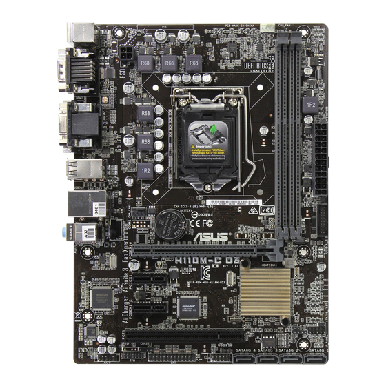
Place this side towards the rear of the chassis H110M-C D3 1.2.3 Motherboard layout 18.2cm(7.2in) CPU_FAN KBMS ATX12V LGA1151 USB5~8 CHA_FAN LAN_USB3_34 BATTERY AUDIO USB3_12 PCIEX16 H110M-C D3 8111H PCIEX1_1 Intel ® Super H110 PCIEX1_2 1083 PCI1 SPEAKER F_PANEL 128Mb... -
Page 11: Central Processing Unit (Cpu)
H110 Serial ATA 6.0 Gb/s connector (7-pin SATA6G_1~4) 1-18 ® 10. USB 2.0 connectors (10-1 pin USB910) 1-16 11. LPT connector (26-1 pin LPT) 1-15 12. Chassis intrusion connector (4-1 pin CHASSIS) 1-12 13. TPM connector (14-1 pin TPM) 1-20 14. Front panel audio connector (10-1 pin AAFP) 1-18 Central Processing Unit (CPU) This motherboard comes with a surface mount LGA1151 socket designed for the 6th Generation Intel Core™ i7 / Core™ i5 / Core™ i3, Pentium and Celeron processors. ® ® ® H110M-C D3 H110M-C D3 CPU socket LGA1151 ASUS H110M-C D3... -
Page 12: Installing The Cpu
Unplug all power cables before installing the CPU. • Ensure that you install the correct CPU designed for the LGA1151 socket only. DO NOT install a CPU designed for LGA1150, LGA1155 and LGA1156 sockets on the LGA1151 socket. • Upon purchase of the motherboard, ensure that the PnP cap is on the socket and the socket contacts are not bent. Contact your retailer immediately if the PnP cap is missing, or if you see any damage to the PnP cap/socket contacts/motherboard components. • Keep the cap after installing the motherboard. ASUS will process Return Merchandise Authorization (RMA) requests only if the motherboard comes with the cap on the LGA1151 socket. • The product warranty does not cover damage to the socket contacts resulting from incorrect CPU installation/removal, or misplacement/loss/incorrect removal of the PnP cap. 1.3.1 Installing the CPU Chapter 1: Product introduction... -
Page 13: Cpu Heatsink And Fan Assembly Installation
1.3.2 CPU heatsink and fan assembly installation Apply the Thermal Interface Material to the CPU heatsink and CPU before you install the heatsink and fan if necessary. ASUS H110M-C D3... - Page 14 To install the CPU heatsink and fan assembly To uninstall the CPU heatsink and fan assembly Chapter 1: Product introduction...
-
Page 15: System Memory
System memory 1.4.1 Overview This motherboard comes with four Double Data Rate 3 (DDR3) Dual Inline Memory Module (DIMM) sockets. The figure illustrates the location of the DDR3 DIMM sockets: Channel Sockets Channel A DIMM_A1 Channel B DIMM_B1 H110M-C D3 H110M-C D3 240-pin DDR3 DIMM sockets 1.4.2 Memory configurations You may install 2 GB, 4 GB, and 8 GB unbuffered non-ECC DDR3 DIMMs into the DIMM sockets. You can refer to the recommended memory population below. Recommended memory configurations ASUS H110M-C D3... - Page 16 ® I nstall a 64-bit Windows OS if you want to install 4GB or more on the ® motherboard. F or more details, refer to the Microsoft support site at http://support.microsoft. ® com/kb/929605/en-us. • The default memory operation frequency is dependent on its Serial Presence Detect (SPD), which is the standard way of accessing information from a memory module. Under the default state, some memory modules for overclocking may operate at a lower frequency than the vendor-marked value. To operate at the vendor-marked or at a higher frequency, refer to section 2.5 Ai Tweaker menu for manual memory frequency adjustment. • Always install the DIMMS with the same CAS Latency. For an optimum compatibility, we recommend that you install memory modules of the same version or data code (D/C) from the same vendor. Check with the vendor to get the correct memory modules. • For system stability, use a more efficient memory cooling system to support a full memory load (2 DIMMs) or overclocking condition. Visit the ASUS website at www.asus.com for the latest QVL. Chapter 1: Product introduction...
-
Page 17: Installing A Dimm
1.4.3 Installing a DIMM To remove a DIMM ASUS H110M-C D3... -
Page 18: Expansion Slots
Expansion slots In the future, you may need to install expansion cards. The following sub-sections describe the slots and the expansion cards that they support. Unplug the power cord before adding or removing expansion cards. Failure to do so may cause you physical injury and damage motherboard components. 1.5.1 Installing an expansion card To install an expansion card: Before installing the expansion card, read the documentation that came with it and make the necessary hardware settings for the card. Remove the system unit cover (if your motherboard is already installed in a chassis). -
Page 19: Headers And Jumpers
– – – Headers and Jumpers Clear RTC RAM (2-pin CLRTC) This header allows you to clear the Real Time Clock (RTC) RAM in CMOS. You can clear the CMOS memory of date, time, and system setup parameters by erasing the CMOS RTC RAM data. The onboard button cell battery powers the RAM data in CMOS, which include system setup information such as system passwords. CLRTC H110M-C D3 PIN 1 H110M-C D3 Clear RTC RAM To erase the RTC RAM: Turn OFF the computer and unplug the power cord. Use a metal object such as a screwdriver to short the two pins. Plug the power cord and turn ON the computer. Hold down the <Del> key during the boot process and enter BIOS setup to re- enter data. ASUS H110M-C D3 1-11... -
Page 20: Connectors
Chassis intrusion header (4-1 pin CHASSIS) This header is for a chassis-mounted intrusion detection sensor or switch. Connect one end of the chassis intrusion sensor or switch cable to this header. The chassis intrusion sensor or switch sends a high-level signal to this header when a chassis component is removed or replaced. The signal is then generated as a chassis intrusion event. By default, the pin labeled “Chassis Signal” and “Ground” are shorted with a jumper cap. Remove the jumper caps only when you intend to use the chassis intrusion detection feature. CHASSIS H110M-C D3 H110M-C D3 Chassis intrusion connector 1-12 Chapter 1: Product introduction... - Page 22 Audio 2.1, 4.1, 5.1, or 7.1-channel configuration Headset Port 4-channel 6-channel 8-channel 2-channel Light Blue (Rear panel) Line In Rear Speaker Out Rear Speaker Out Rear Speaker Out Lime (Rear panel) Line Out Front Speaker Out Front Speaker Out Front Speaker Out Pink (Rear panel) Mic In Mic In Bass/Center Bass/Center Lime (Front panel) Side Speaker Out USB 3.0 ports 3 and 4. These 9-pin Universal Serial Bus (USB) ports are for USB 3.0 devices. • The plugged USB 3.0 device may run on xHCI or EHCI mode, depending on the operating system’s setting. •...
-
Page 23: Internal Connectors
CPU_FAN CHA_FAN H110M-C D3 H110M-C D3 Fan connectors Do not forget to connect the fan cables to the fan connectors. Insufficient air flow inside the system may damage the motherboard components. These are not jumpers! Do not place jumper caps on the fan connectors! The CPU_FAN connector supports a CPU fan of maximum 1A (12 W) fan power. Only the 4-pin CPU fan supports the ASUS Fan Xpert 3 feature. LPT connector (26-1 pin LPT) The LPT (Line Printing Terminal) connector supports devices such as a printer. LPT standardizes as IEEE 1284, which is the parallel port interface on IBM PC-compatible computers. PIN 1 H110M-C D3 H110M-C D3 Parallel Port connector ASUS H110M-C D3 1-15... -
Page 24: Usb 3.0/Usb 2.0 Connector
USB 3.0 connector (20-1 pin USB3_12) This connector allows you to connect a USB 3.0 module for additional USB 3.0 front or rear panel ports. With an installed USB 3.0 module, you can enjoy all the benefits of USB 3.0 including faster data transfer speeds of up to 5 Gbps, faster charging time for USB-chargeable devices, optimized power efficiency, and backward compatibility with USB 2.0. USB3_12 PIN 1 USB3+5V USB3+5V IntA_P1_SSRX- IntA_P2_SSRX- IntA_P1_SSRX+ IntA_P2_SSRX+ IntA_P1_SSTX- IntA_P2_SSTX- IntA_P1_SSTX+ H110M-C D3 IntA_P2_SSTX+ IntA_P1_D- IntA_P2_D- IntA_P1_D+ IntA_P2_D+ H110M-C D3 USB3.0 Front panel connector The USB 3.0 module is purchased separately. 1-16 Chapter 1: Product introduction... -
Page 25: Atx Power/Speaker Connector
+5 Volts Power OK -5 Volts +5 Volts +5 Volts PSON# H110M-C D3 +3 Volts -12 Volts +3 Volts +3 Volts PIN 1 H110M-C D3 ATX power connectors • For a fully configured system, we recommend that you use a power supply unit (PSU) that complies with ATX 12 V Specification 2.0 (or later version) and provides a minimum power of 350 W. • DO NOT forget to connect the 4-pin ATX +12V power plug. Otherwise, the system will not boot up. • We recommend that you use a PSU with higher power output when configuring a system with more power-consuming devices or when you intend to install additional devices. The system may become unstable or may not boot up if the power is inadequate. - Page 26 This connector is for a chassis-mounted front panel audio I/O module that supports either HD Audio or legacy AC`97 audio standard. Connect one end of the front panel audio I/O module cable to this connector. AAFP PIN 1 PIN 1 H110M-C D3 HD-audio-compliant Legacy AC’97 pin definition compliant definition H110M-C D3 Front panel audio connector • We recommend that you connect a high-definition front panel audio module to this connector to avail of the motherboard’s high-definition audio capability. • If you want to connect a high-definition front panel audio module to this connector, set the Front Panel Type item in the BIOS setup to [HD Audio]. If you want to connect an AC’97 front panel audio module to this connector, set the item to [AC97]. By default, this connector is set to [HD Audio]. See section Onboard Devices Configuration for details. Intel H110 Serial ATA 6.0Gb/s connectors (7-pin SATA6G_1~4) ®...
-
Page 27: System Panel Connector
System panel connector (10-1 pin F_PANEL) This connector supports several chassis-mounted functions. F_PANEL +PWR LED PWR BTN PIN 1 H110M-C D3 +HDD_LED RESET H110M-C D3 System panel connector • System power LED (2-pin PWR_LED) This 2-pin connector is for the system power LED. Connect the chassis power LED cable to this connector. The system power LED lights up when you turn on the system power, and blinks when the system is in sleep mode. • Hard disk drive activity LED (2-pin HDD_LED) This 2-pin connector is for the HDD Activity LED. Connect the HDD Activity LED cable to this connector. The HDD LED lights up or flashes when data is read from or written to the HDD. • ATX power button/soft-off button (2-pin PWR_BTN) This connector is for the system power button. - Page 28 TPM connector (14-1 pin TPM) This connector supports a Trusted Platform Module (TPM) system, which can securely store keys, digital certificates, passwords, and data. A TPM system also helps enhance network security, protects digital identities, and ensures platform integrity. PIN 1 H110M-C D3 H110M-C D3 TPM connector The TPM module is purchased separately. 1-20 Chapter 1: Product introduction...
-
Page 30: Installing An Operating System
® detailed information. Windows 7 and USB 3.0 driver for 100 Series ® Based on the chipset specification, the 100 series requires USB 3.0 drivers to be preloaded in order to use USB keyboard/mouse during Windows 7 installation. This section is a guide ® on preloading USB 3.0 drivers and installing Windows ® Method 1: Using SATA ODD & USB devices Load USB 3.0 drivers using the ASUS support DVD and install Windows 7 using a USB ® device. Requirement: • 1 x ASUS support DVD • 1 x Windows 7 installation source ® • 1 x SATA ODD •... - Page 31 Select the USB ODD or USB storage device as the boot device. The USB 3.0 driver will be loaded automatically during installation startup. The “Setup is starting...” screen will show up if the USB 3.0 driver is loaded correctly. Follow the onscreen instructions to complete the Windows 7 installation. ® ASUS H110M-C D3 1-23...
- Page 32 Method 2: Using a modified Windows 7 ISO ® Load USB 3.0 drivers and install Windows 7 using a modified Windows 7 installation DVD. ® ® Requirement: • 1 x ASUS support DVD • 1 x Windows 7 installation source ® • 1 x Working system (PC or notebook) • 1 x SATA ODD On your working system, create an ISO image file of the Windows 7 installation ® source using a third-party ISO software. Copy both “Auto_Unattend.xml” and “Auto_Unattend” folder from the root directory of the ASUS supporting DVD to your system. Edit the ISO file and add both “Auto_Unattend.xml” and “Auto_Unattend” folder into the ISO file. Burn this ISO file onto an empty DVD to create a modified Windows 7 installation ® DVD. Insert the modified Windows 7 installation DVD into an ODD on your 100 series ®...
- Page 36 - S elect the folder to save the modified Windows 7 installation ISO file and click ® Next. - Once completed, click OK to finish. - B urn this ISO file onto an empty DVD to create a modified Windows ® installation DVD. Insert the modified Windows 7 installation DVD into an ODD or connect the USB ® storage device with modified Windows 7 installation files onto your 100 series ® platform. Power on your system and press F8 during POST (Power-On Self Test) to enter the boot screen. Select the ODD or USB storage device as the boot device. The USB 3.0 driver will be loaded automatically during installation startup. The “Setup is starting...” screen will show up if the USB 3.0 driver is loaded correctly. Follow the onscreen instructions to complete the Windows 7 installation. ® 1-28 Chapter 1: Product introduction...
-
Page 37: Chapter 2 Bios Information
Managing and updating your BIOS Save a copy of the original motherboard BIOS file to a USB flash disk in case you need to restore the BIOS in the future. Copy the original motherboard BIOS using the ASUS Update utility. -
Page 38: Asus Ez Flash
2.1.2 ASUS EZ Flash 3 The ASUS EZ Flash 3 feature allows you to update the BIOS without using an OS‑based utility. • Ensure to load the BIOS default settings to ensure system compatibility and stability. Select the Load Optimized Defaults item under the Exit menu. See section 2.10 Exit Menu for details. -
Page 39: Asus Crashfree Bios 3 Utility
2.1.3 ASUS CrashFree BIOS 3 utility The ASUS CrashFree BIOS 3 is an auto recovery tool that allows you to restore the BIOS file when it fails or gets corrupted during the updating process. You can restore a corrupted BIOS file using the motherboard support DVD or a USB flash drive that contains the updated BIOS file. - Page 40 ENTER to select boot device ESC to boot using defaults P2: ST3808110AS (76319MB) aigo miniking (250MB) UEFI: (FAT) ASUS DRW-2014L1T(4458MB) P1: ASUS DRW-2014L1T(4458MB) UEFI: (FAT) aigo miniking (250MB) Enter Setup When the booting message appears, press <Enter> within five (5) seconds to enter FreeDOS prompt.
- Page 41 DO NOT shut down or reset the system while updating the BIOS to prevent system boot failaure. Ensure to load the BIOS default settings to ensure system compatibility and stability. Select the Load Optimized Defaults item under the Exit BIOS menu. See section 2.10 Exit Menu for details. ASUS H110M-C D3 2‑5...
-
Page 42: Bios Setup Program
The BIOS setup screens shown in this section are for reference purposes only, and may not exactly match what you see on your screen. • Visit the ASUS website at www.asus.com to download the latest BIOS file for this motherboard. •... - Page 43 Searches FAQ Loads optimized Saves the changes default settings and resets the Selects the boot system device priority The boot device options vary depending on the devices you installed to the system. ASUS H110M-C D3 2‑7...
-
Page 44: Advanced Mode
2.2.2 Advanced Mode The Advanced Mode provides advanced options for experienced end‑users to configure the BIOS settings. The figure below shows an example of the Advanced Mode. Refer to the following sections for the detailed configurations. To access the EZ Mode, click EzMode(F7) or press <F7>. Q-Fan MyFavorite Quick Note... -
Page 45: Menu Bar
This button above the menu bar allows you to key in notes of the activities that you have done in BIOS. • The Quick Note function does not support the following keyboard functions: delete, cut, copy and paste. • You can only use the alphanumeric characters to enter your notes. ASUS H110M-C D3... -
Page 46: Hot Keys
Hot keys This button above the menu bar contains the navigation keys for the BIOS setup program. Use the navigation keys to select items in the menu and change the settings. Scroll bar A scroll bar appears on the right side of a menu screen when there are items that do not fit on the screen. - Page 47 Select the fan that you want to configure and to view its current status. Click and drag the speed points to adjust the fans’ operating speed. Click Apply to save the changes then click Exit (ESC). ASUS H110M-C D3 2-11...
-
Page 48: My Favorites
My Favorites MyFavorites is your personal space where you can easily save and access your favorite BIOS items. 2-12 Chapter 2: Getting started... - Page 49 You cannot add the following items to My Favorite items: • User‑managed items such as language and boot order Click Exit (ESC) or press <esc> key to close Setup Tree Map screen. Go to My Favorites menu to view the saved BIOS items. ASUS H110M-C D3 2‑13...
-
Page 50: Main Menu
Main menu The Main menu screen appears when you enter the Advanced Mode of the BIOS Setup program. The Main menu provides you an overview of the basic system information, and allows you to set the system date, time, language, and security settings. Language [English] Allows you to choose the BIOS language version from the options. -
Page 51: Administrator Password
To clear the user password, follow the same steps as in changing a user password, but press <Enter> when prompted to create/confirm the password. After you clear the password, the User Password item on top of the screen shows Not Installed. ASUS H110M-C D3 2‑15... -
Page 52: Ai Tweaker Menu
Ai Tweaker menu The Ai Tweaker menu items allow you to configure overclocking‑related items. Be cautious when changing the settings of the Ai Tweaker menu items. Incorrect field values can cause the system to malfunction. The configuration options for this section vary depending on the CPU and DIMM model you installed on the motherboard. -
Page 53: Dram Timing Control
<+> and <‑> keys to adjust the value. To restore the default setting, type [auto] using the keyboard and press the <Enter> key. Changing the values in this menu may cause the system to become unstable! If this happens, revert to the default settings. ASUS H110M-C D3 2‑17... - Page 54 Internal CPU Power Management The subitems in this menu allow you to set the CPU ratio and features. Intel SpeedStep(tm) [Enabled] ® Allows you to enable or disable the Intel SpeedStep Technology (EIST). ® [Disabled] Disables this function. [Enabled] The operating system dynamically adjusts the processor voltage and core frequency which may result in decreased average consumption and decreased average heat production.
- Page 55 DRAM REF Voltage Control The subitems in this menu allow you to set the DRAM reference voltage on the control lines from the memory bus. You can use the <+> or <‑> keys to adjust the value. ASUS H110M-C D3 2-19...
-
Page 56: Advanced Menu
Advanced menu The Advanced menu items allow you to change the settings for the CPU and other system devices. Be cautious when changing the settings of the Advanced menu items. Incorrect field values can cause the system to malfunction. CPU Configuration The items in this menu show the CPU‑related information that the BIOS automatically detects. -
Page 57: Cpu Power Management Configuration
Allows you to disable or enable the CPU C3 report to OS. Configuration options: [Enabled] [Disabled] CPU C6 Report [Enabled] Allows you to disable or enable the CPU C6 report to OS. Configuration options: [Enabled] [Disabled] ASUS H110M-C D3 2-21... -
Page 58: Platform Misc Configuration
ASPM to take effect. Configuration options: [Disabled] [L1] PEG ASPM [Disabled] This item allows you to select the ASPM state for energy‑saving conditions, or use the ASUS optimized energy saving profile. Configuration options: [Disabled] [Auto] [ASPM L0s] [ASPM... -
Page 59: Graphics Configuration
Configuration options: [Enabled] [Disabled] PCH Configuration This item allows you to configure the PCI Express configuration settings. PCI Express Configuration PCIe Speed [Auto] Allows you to configure the PCIe speed. Configuration options: [Auto] [Gen1] [Gen2] ASUS H110M-C D3 2‑23... -
Page 60: Pch Storage Configuration
PCH Storage Configuration While entering Setup, the BIOS automatically detects the presence of SATA devices. The SATA Port items show Not Present if no SATA device is installed to the corresponding SATA port. SATA Controller(s) [Enabled] Enables or disables onboard the SATA device. Configuration options: [Disabled] [Enabled] The following items appear only when you set SATA Controller(s) to [Enabled]. -
Page 61: Onboard Devices Configuration
[Disabled] Disables this function. Serial Port Configuration The sub‑items in this menu allow you to set the serial port configuration. Serial Port [On] Allows you to enable or disable the serial port (COM).Configuration options: [On] [Off] ASUS H110M-C D3 2‑25... -
Page 62: Parallel Port Configuration
Change Settings [IO=3F8h; IRQ=4] This item appears only when you set the Serial Port to [Enabled] and allows you to select the Serial Port base address. Configuration options: [IO=3F8h; IRQ=4] [IO=2F8h; IRQ=3] [IO=3E8h; IRQ=4] [IO=2E8h; IRQ=3] Parallel Port Configuration The sub‑items in this menu allow you to set the parallel port configuration. Parallel Port [On] Allows you to enable or disable the parallel port (LPT/LPTE). -
Page 63: Network Stack Configuration
The following two items appear only when you set the previous item to [Enabled]. Ipv4 / Ipv6 PXE Support [Enabled] This item allows you to enable or disable the Ipv4/Ipv6 PXE wake event. Configuration options: [Disabled] [Enabled] ASUS H110M-C D3 2‑27... -
Page 64: Monitor Menu
Monitor menu The Monitor menu displays the system temperature/power status, and allows you to change the fan settings. Scroll down to display the other BIOS items. CPU / MotherBoard Temperature [xxxºC/xxxºF]/ [Ignore] The onboard hardware monitor automatically detects and displays the CPU and motherboard temperatures. - Page 65 Use the <+> and <‑> keys to adjust the minimum CPU fan duty cycle. The values range from 20% to 100%. When the CPU temperature is under the lower limit, the CPU fan will operate at the minimum duty cycle. ASUS H110M-C D3 2-29...
- Page 66 Chassis Fan Q-Fan Control [DC Mode] [PWM mode] Enables the chassis Q‑Fan control in PWM mode for 4‑pin chassis fan. [DC mode] Enables the chassis Q‑Fan control in DC mode for 3‑pin chassis fan. [Disabled] Disables the chassis Q‑Fan control feature. The following items appear only when you set the Chassis Fan Q‑Fan Control to [PWM Mode] or [DC Mode].
-
Page 67: Boot Menu
Next Boot after AC Power Loss [Normal Boot] [Normal Boot] Returns to normal boot on the next boot after AC power loss. [Fast Boot] Accelerates the boot speed on the next boot after AC power loss. ASUS H110M-C D3 2‑31... - Page 68 Boot Logo Display [Auto] [Auto] Adjusts logo automatically based on Windows display requirements. ® [Full Screen] Maximize the boot logo size. [Disabled] Hide the logo during POST. POST Delay Time [3 sec] This item appears only when you set Boot Logo Display to [Auto] and [Full Screen]. This item allows you to select the desired additional POST waiting time to easily enter the BIOS setup.
-
Page 69: Secure Boot
This item allows you to immediately load the default Security Boot keys, Platform key (PK), Key‑exchange Key (KEK), Signature database (db), and Revoked Signatures (dbx). When the default Secure boot keys are loaded, all the Secure Boot keys’ state will change from Unloaded mode to loaded mode. ASUS H110M-C D3 2‑33... - Page 70 Clear Secure Boot keys This item appears only when you load the default Secure Boot keys. This item allows you to clear all the previously applied Secure Boot keys. Save Secure Boot Keys This item allows you to save all the Secure Boot keys to a USB storage device. PK Management The Platform Key (PK) locks and secures the firmware from any non‑permissible changes.
-
Page 71: Boot Option Priorities
OS in Safe Mode, press <F8 > after POST (Windows 8 not supported). • To select the boot device during system startup, press <F8> when ASUS Logo appears. Boot Override These items displays the available devices. The number of device items that appears on the screen depends on the number of devices installed in the system. -
Page 72: Tool Menu
<Enter> to display the submenu. ASUS EZ Flash 3 Utility Allows you to run ASUS EZ Flash 3. Press [Enter] to launch the ASUS EZ Flash 3 screen. For more details, see section 2.1.2 ASUS EZ Flash 3. Setup Animator [Disabled] Enables or disables the Setup animator. -
Page 73: Exit Menu
<Esc>, a confirmation window appears. Select OK to discard changes and exit. Launch EFI Shell from USB drives This option allows you to attempt to launch the EFI Shell application (shellx64.efi) from one of the available USB devices. ASUS H110M-C D3 2‑37... - Page 74 2‑38 Chapter 2: Getting started...
-
Page 75: Appendices
Cet appareil est conforme aux normes CNR exemptes de licence d’Industrie Canada. Le fonctionnement est soumis aux deux conditions suivantes : (1) cet appareil ne doit pas provoquer d’interférences et (2) cet appareil doit accepter toute interférence, y compris celles susceptibles de provoquer un fonctionnement non souhaité de l’appareil. ASUS H110M-C D3... -
Page 76: Canadian Department Of Communications Statement
ASUS Recycling/Takeback Services ASUS recycling and takeback programs come from our commitment to the highest standards for protecting our environment. We believe in providing solutions for you to be able to responsibly recycle our products, batteries, other components as well as the packaging materials. - Page 77 CE. das Diretivas da CE. Para mais detalhes, consulte a Declaração de Компания ASUS заявляет, что это устройство соответствует основным Conformidade CE. требованиям и другим соответствующим условиям европейских Română Prin prezenta, AsusTek Inc. declară faptul că acest dispozitiv директив.
-
Page 78: Asus Contact Information
+1-510-739-3777 +1-510-608-4555 Web site http://www.asus.com/us/ Technical Support Support fax +1-812-284-0883 General support +1-812-282-2787 Online support http://www.service.asus.com/ ASUS COMPUTER GmbH (Germany and Austria) Address Harkort Str. 21-23, D-40880 Ratingen, Germany +49-2102-959931 Web site http://www.asus.com/de Online contact http://eu-rma.asus.com/sales Technical Support Telephone +49-2102-5789555... - Page 79 ASUS H110M-C D3...
Need help?
Do you have a question about the H110M-C D3 and is the answer not in the manual?
Questions and answers