Table of Contents
Advertisement
Quick Links
Advertisement
Table of Contents

Related Manuals for Asus H110M-CS


Summary of Contents for Asus H110M-CS
- Page 1 H110M-CS...
- Page 2 Product warranty or service will not be extended if: (1) the product is repaired, modified or altered, unless such repair, modification of alteration is authorized in writing by ASUS; or (2) the serial number of the product is defaced or missing.
-
Page 3: Table Of Contents
Contents Safety information ..................iv About this guide ..................iv Package contents ..................vi H110M-CS specifications summary ............vi Chapter 1: Product introduction Motherboard overview ................1-1 Central Processing Unit (CPU) ..............1-7 System memory ..................1-8 Intel SBB support ................... 1-9 ®... -
Page 4: Safety Information
Safety information Electrical safety • To prevent electrical shock hazard, disconnect the power cable from the electrical outlet before relocating the system. • When adding or removing devices to or from the system, ensure that the power cables for the devices are unplugged before the signal cables are connected. If possible, disconnect all power cables from the existing system before you add a device. - Page 5 Refer to the following sources for additional information and for product and software updates. ASUS websites The ASUS website provides updated information on ASUS hardware and software products. Refer to the ASUS contact information. Optional documentation Your product package may include optional documentation, such as warranty flyers, that may have been added by your dealer.
-
Page 6: Package Contents
Extreme Memory Profile (XMP) Memory * Refer to www.asus.com for the latest Memory QVL (Qualified Vendors List). ** Due to Intel® chipset limitation, DDR4 2133 MHz and higher memory modules on XMP mode will run at the maximum transfer rate of DDR4 2133 Mhz. - Page 7 - ASUS Overvoltage Protection - World-class circuit-protecting power design - ASUS DIGI+ VRM - 3+1+1 Phase digital power design - ASUS DRAM Overcurrent Protection - Enhanced DRAM Overcurrent Protection - ASUS Stainless Steel Back I/O - 3X more durable corrosion-resistant coating Superb Performance UEFI BIOS...
- Page 8 1 x System panel connector 128 Mb Flash ROM, UEFI AMI BIOS, PnP, DMI 2.0, WfM2.0, SM BIOS 3.0, ACPI 5.0, Multi-language BIOS, ASUS EZ Flash 3, ASUS CrashFree BIOS 3, BIOS features My Favorites, Quick Note, Last Modified Log, F12 PrintScreen function, and...
-
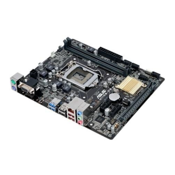
Page 9: Motherboard Overview
17.78cm(7.0in) CPU_FAN KBMS CHA_FAN DIGI +VRM ATX12V 2168 Place this side towards the rear of the chassis LGA1151 USB3_34 Realtek 8111H USB78 USB3_12 USB910 LAN_USB56 H110M-CS AUDIO PCIEX1_1 Intel ® Super H110 PCIEX1_2 128Mb BIOS AAFP PCIEX16 Scan the QR code to get the detailed pin definitions. ASUS H110M-CS... - Page 10 F_LAD1 security, protects digital identities, and ensures F_LAD0 PIN 1 platform integrity. ATX power connectors (24-pin EATXPWR, 4-pin ATX12V) Correctly orient the ATX power supply plugs into these connectors and push down firmly until the connectors completely fit. • For a fully configured system, we recommend that you use a power supply unit (PSU) that complies with ATX 12 V Specification 2.0 (or later version) and provides a minimum power of 350 W. • If you are uncertain about the minimum power supply requirement for your system, refer to the Recommended Power Supply Wattage Calculator at http://support.asus.com/PowerSupplyCalculator/ PSCalculator.aspx?SLanguage=en-us for details. Intel LGA1151 CPU socket ® Install Intel LGA1151 CPU into this surface mount LGA1151 socket, which is ® designed for 6th Generation Intel Core™ i7 / i5 / i3, Pentium , and Celeron ® ® ® processors. For more details, refer to Central Processing Unit (CPU).
- Page 11 Speaker connector (4-pin SPEAKER) This 4-pin connector is for the chassis-mounted system warning speaker. The speaker allows you to hear system beeps and warnings. PCI Express 3.0/2.0 x16 slot This motherboard supports PCI Express 3.0/2.0 x16 graphic cards complying with the PCI Express specifications. Clear RTC RAM (2-pin CLRTC) CLRTC This header allows you to clear the CMOS RTC RAM data of the system setup information such as date, time, and system passwords. To erase the RTC RAM: PIN 1 Turn OFF the computer and unplug the power cord. Use a metal object such as a screwdriver to short the two pins. Plug the power cord and turn ON the computer. Hold down the <Del> key during the boot process and enter BIOS setup to re-enter data. If the steps above do not help, remove the onboard battery and short the two pins again to clear the CMOS RTC RAM data. After clearing the CMOS, reinstall the battery. ASUS H110M-CS...
- Page 12 Front panel audio connector (10-1 pin AAFP) This connector is for a chassis-mounted front panel audio I/O module that supports either HD Audio or legacy AC`97 audio standard. Connect one end of the front panel audio I/O module cable to this connector. • We recommend that you connect a high-definition front panel audio module to this connector to avail of the motherboard’s high-definition audio capability. • If you want to connect a high-definition front panel audio module to this connector, set the Front Panel Type item in the BIOS setup to [HD Audio]. If you want to connect an AC’97 front panel audio module to this connector, set the item to [AC97]. By default, this connector is set to [HD Audio]. Serial port connector (10-1 pin COM) Connect the serial port module cable to this connector, then install the module to a slot opening at the back of the system chassis. PCI Express 2.0 x1 slots This motherboard has two PCI Express 2.0 x1 slots that support PCI Express x1 network cards, SCSI cards, and other cards that comply with the PCI Express specifications. IRQ assignments for this motherboard PCIEx16_1 shared –...
- Page 13 LAN port LAN port LED indications Activity/Link LED Speed LED Status Description Status Description No link 10Mbps connection Orange Linked ORANGE 100Mbps connection Orange (Blinking) Data activity GREEN 1Gbps connection Orange (Blinking Ready to wake up then steady) from S5 mode Line In port (light blue). This port connects to the tape, CD, DVD player, or other audio sources. Line Out port (lime). This port connects to a headphone or a speaker. In the 4.1, 5.1 and 7.1-channel configurations, the function of this port becomes Front Speaker Out. ASUS H110M-CS...
- Page 14 Microphone port (pink). This port connects to a microphone. Refer to the audio configuration table for the function of the audio ports in 2.1, 4.1, 5.1, or 7.1-channel configuration. Audio 2.1, 4.1, 5.1, or 7.1-channel configuration Headset Port 4.1-channel 5.1-channel 7.1-channel 2.1-channel Light Blue (Rear Line In Rear Speaker Out Rear Speaker Out Rear Speaker Out panel) Lime (Rear panel) Line Out Front Speaker Out Front Speaker Out Front Speaker Out Pink (Rear panel) Mic In Mic In Bass/Center Bass/Center Lime (Front panel) Side Speaker Out To configure a 7.1-channel audio output: Use a chassis with HD audio module in the front panel to support a 7.1-channel audio output.
-
Page 15: Central Processing Unit (Cpu)
Central Processing Unit (CPU) This motherboard comes with a surface mount LGA1151 socket designed for 6th Generation Intel Core™ i7 / i5 / i3, Pentium , and ® ® Celeron processors. ® Unplug all power cables before installing the CPU. • Ensure that you install the correct CPU designed for the LGA1151 socket only. DO NOT install a CPU designed for LGA1150, LGA1155 and LGA1156 sockets on the LGA1151 socket. • Upon purchase of the motherboard, ensure that the PnP cap is on the socket and the socket contacts are not bent. Contact your retailer immediately if the PnP cap is missing, or if you see any damage to the PnP cap/socket contacts/motherboard components. • Keep the cap after installing the motherboard. ASUS will process Return Merchandise Authorization (RMA) requests only if the motherboard comes with the cap on the LGA1151 socket. • The product warranty does not cover damage to the socket contacts resulting from incorrect CPU installation/removal, or misplacement/loss/incorrect removal of the PnP cap. Installing the CPU Apply the Thermal Interface Material to the CPU heatsink and CPU before you install the heatsink and fan if necessary. ASUS H110M-CS... -
Page 16: System Memory
(D/C) from the same vendor. Check with the vendor to get the correct memory modules. • According to Intel CPU spec, DIMM voltage below 1.35V is recommended to protect ® the CPU. • Due to the memory address limitation on 32-bit Windows OS, when you install 4GB ® or more memory on the motherboard, the actual usable memory for the OS can be about 3GB or less. For effective use of memory, we recommend that you do any of the following: Use a maximum of 3 GB system memory if you are using a 32-bit Windows OS. ® I nstall a 64-bit Windows OS if you want to install 4GB or more on the ® motherboard. F or more details, refer to the Microsoft support site at http://support.microsoft. ® com/kb/929605/en-us. Visit the ASUS website at www.asus.com for the latest QVL. Installing a DIMM To remove a DIMM Chapter 1: Product introduction... -
Page 17: Intel ® Sbb Support
® the-box value for small business. Intel SBB requires MEI driver (AMT host software kit) to be installed and running. ® Platform requirements: • Windows 7 (32/64-bit) / Windows 8.1 (64-bit) / Windows 10 (64-bit) ® ® ® • PCH with 6th-generation Intel Core™ CPU (100 Series platforms) with 2MB Intel ® ® Management Engine 11.0 firmware installed CPU and chipsets requirements: • Intel Core™ i3 / i5 /i7 with one of these chipsets: H110, B150, H170, Q170 ® Other requirements: • Local Administrator rights on the target machine • Visit the ASUS website at www.asus.com for the latest CPU QVL (Qualified Vendors List). • Uninstall SBA4.0 before you install and upgrade to the latest version. ASUS H110M-CS... -
Page 18: Chapter 2: Bios Information
To enter BIOS Setup after POST: • Press <Ctrl>+<Alt>+<Del> simultaneously. • Press the reset button on the system chassis. • Press the power button to turn the system off then back on. Do this option only if you failed to enter BIOS Setup using the first two options. Using the power button, reset button, or the <Ctrl>+<Alt>+<Del> keys to force reset from a running operating system can cause damage to your data or system. We recommend you always shut down the system properly from the operating system. • The BIOS setup screens shown in this section are for reference purposes only, and may not exactly match what you see on your screen. • Visit the ASUS website at www.asus.com to download the latest BIOS file for this motherboard. • If the system becomes unstable after changing any BIOS setting, load the default settings to ensure system compatibility and stability. Select the Load Optimized Defaults item under the Exit menu or press hotkey F5. • If the system fails to boot after changing any BIOS setting, try to clear the CMOS and reset the motherboard to the default value. See section Motherboard overview for information on how to erase the RTC RAM. BIOS menu screen The BIOS setup program can be used under two modes: EZ Mode and Advanced Mode. Press <F7> to change between the two modes. ASUS H110M-CS... -
Page 19: Ez Mode
EZ Mode By default, the EZ Mode screen appears when you enter the BIOS setup program. The EZ Mode provides you an overview of the basic system information, and allows you to select the display language, system performance mode, fan profile and boot device priority. To access the Advanced Mode, click Advanced Mode(F7) or press <F7>. The default screen for entering the BIOS setup program can be changed. Refer to the Setup Mode item under the Boot menu for details. Displays the system properties of the selected mode. Click <Enter> to Displays the CPU/motherboard switch EZ System Tuning modes temperature, CPU voltage output, Selects the display CPU/chassis fan speed, DRAM language of the BIOS status, and SATA information setup program... -
Page 20: Advanced Mode
Q-Fan control Language Hot Keys Menu bar Configuration fields Scroll bar Last modified General help Sub-menu item settings Menu items Goes back to EZ Mode Popup window Search on FAQs Displays the CPU temperature, CPU and memory voltage output ASUS H110M-CS... -
Page 21: Exit Menu
Search on FAQ Move your mouse over this button to show a QR code. Scan this QR code with your mobile device to connect to the ASUS BIOS FAQ web page. You can also scan the QR code below. Exit menu The Exit menu items allow you to load the optimal default values for the BIOS items, and save or discard your changes to the BIOS items. Load Optimized Defaults This option allows you to load the default values for each of the parameters on the Setup menus. When you select this option or if you press <F5>, a confirmation window appears. Select OK to load the default values. Save Changes & Reset Once you are finished making your selections, choose this option from the Exit menu to ensure the values you selected are saved. When you select this option or if you press <F10>, a confirmation window appears. Select OK to save changes and exit. Discard Changes and Exit This option allows you to exit the Setup program without saving your changes. When you select this option or if you press <Esc>, a confirmation window appears. Select OK to discard changes and exit. Launch EFI Shell from USB drives This option allows you to attempt to launch the EFI Shell application (shellx64.efi) from one of the available USB devices. Chapter 2: Getting started... -
Page 22: Appendices
Consult the dealer or an experienced radio/TV technician for help. The use of shielded cables for connection of the monitor to the graphics card is required to assure compliance with FCC regulations. Changes or modifications to this unit not expressly approved by the party responsible for compliance could void the user’s authority to operate this equipment. H110M-CS... - Page 23 IC: Canadian Compliance Statement Complies with the Canadian ICES-003 Class B specifications. This device complies with RSS 210 of Industry Canada. This Class B device meets all the requirements of the Canadian interference-causing equipment regulations. This device complies with Industry Canada license exempt RSS standard(s). Operation is subject to the following two conditions: (1) this device may not cause interference, and (2) this device must accept any interference, including interference that may cause undesired operation of the device.
- Page 24 ASUS Recycling/Takeback Services ASUS recycling and takeback programs come from our commitment to the highest standards for protecting our environment. We believe in providing solutions for you to be able to responsibly recycle our products, batteries, other components as well as the packaging materials.
- Page 25 Slovenščina AsusTek Inc. tukaj izjavlja, da je ta naprava skladna s di conformità CE. temeljnimi zahtevami in drugimi relevantnimi določili direktiv CE. Za več Русский Компания ASUS заявляет, что это устройство соответствует informacij glejte Izjavo CE o skladnosti. основным требованиям и другим соответствующим условиям...
-
Page 26: Asus Contact Information
+1-510-739-3777 +1-510-608-4555 Web site http://www.asus.com/us/ Technical Support Support fax +1-812-284-0883 Telephone +1-812-282-2787 Online support http://qr.asus.com/techserv ASUS COMPUTER GmbH (Germany and Austria) Address Harkort Str. 21-23, D-40880 Ratingen, Germany +49-2102-959931 Web site http://www.asus.com/de Online contact http://eu-rma.asus.com/sales Technical Support Telephone +49-2102-5789555 Support Fax... - Page 27 Appendices...
Need help?
Do you have a question about the H110M-CS and is the answer not in the manual?
Questions and answers