Advertisement
Safe Operation Practices • Set-Up • Operation • Maintenance • Service • Troubleshooting • Warranty
O
'
M
peratOr
s
anual
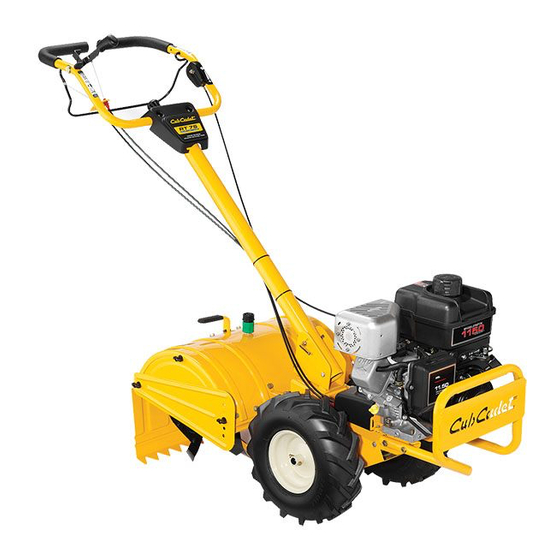
Rear Tine Tiller — RT-75
WARNING
READ AND FOLLOW ALL SAFETY RULES AND INSTRUCTIONS IN THIS MANUAL
BEFORE ATTEMPTING TO OPERATE THIS MACHINE.
FAILURE TO COMPLY WITH THESE INSTRUCTIONS MAY RESULT IN PERSONAL INJURY.
CUB CADET LLC, P.O. BOX 361131 CLEVELAND, OHIO 44136-0019
Printed In USA
Form No. 769-10469
(December 10, 2014)
Advertisement
Table of Contents

Related Manuals for Cub Cadet RT-75


Summary of Contents for Cub Cadet RT-75
- Page 1 READ AND FOLLOW ALL SAFETY RULES AND INSTRUCTIONS IN THIS MANUAL BEFORE ATTEMPTING TO OPERATE THIS MACHINE. FAILURE TO COMPLY WITH THESE INSTRUCTIONS MAY RESULT IN PERSONAL INJURY. CUB CADET LLC, P.O. BOX 361131 CLEVELAND, OHIO 44136-0019 Printed In USA Form No. 769-10469...
-
Page 2: Table Of Contents
See How-to Maintenance and Parts Installation Videos at www.cubcadet.com/tutorials ◊ Call a Customer Support Representative at (800) 965-4CUB ◊ Locate your nearest Cub Cadet Dealer at (877) 282-8684 ◊ Write to Cub Cadet LLC • P.O. Box 361131 • Cleveland, OH • 44136-0019... -
Page 3: Safe Operation Practices
Important Safe Operation Practices WARNING! This symbol points out important safety instructions which, if not followed, could endanger the personal safety and/or property of yourself and others. Read and follow all instructions in this manual before attempting to operate this machine. Failure to comply with these instructions may result in personal injury. - Page 4 When practical, remove gas-powered equipment After striking a foreign object, stop the engine, disconnect from the truck or trailer and refuel it on the ground. the spark plug wire and ground against the engine. If this is not possible, then refuel such equipment on Thoroughly inspect the machine for any damage.
- Page 5 Spark Arrestor If the fuel tank has to be drained, do this outdoors. Observe proper disposal laws and regulations for gas, oil, WARNING! This machine is equipped with an etc. to protect the environment. internal combustion engine and should not be used According to the Consumer Products Safety Commission on or near any unimproved forest-covered, (CPSC) and the U.S.
- Page 6 Safety Symbols This page depicts and describes safety symbols that may appear on this product. Read, understand, and follow all instructions on the machine before attempting to assemble and operate. Symbol Description READ THE OPERATOR’S MANUAL(S) Read, understand, and follow all instructions in the manual(s) before attempting to assemble and operate WARNING—...
-
Page 7: Assembly & Set-Up
Assembly & Set-Up Contents of Carton • One Tiller • One Handlebar Assembly • One Bottle of Engine Oil • Two Cable Ties • One Operator’s Manual • One Engine Operator’s Manual Handle NOTE: Reference to the right or left side of the tiller is determined from the operator’s position behind the machine. - Page 8 Forward & Reverse Clutch Cables Using a cable tie secure the two cables onto the handle about mid-way down the shaft. See Fig. 1-3. To attach the cables, follow these steps: Route the forward (black) clutch cable along the handle assembly on the right-hand side.
- Page 9 Set-Up Secure the throttle cable to the handle with a cable tie as shown in Figure 3-5. Tires The tires on the tiller may be over-inflated for shipping purposes. Reduce the tire pressure before operating the tiller. Recommended operating tire pressure is approximately 20 PSI (check the sidewall of the tire for the manufacturer’s recommended pressure).
-
Page 10: Controls & Features
Controls & Features Reverse Clutch Handle Forward Clutch Bail Handle Pivot Control Knob Throttle Control Handle Adjustment Lock Depth Adjustment Lever Neutral Lever Tine Shield Wash Nozzle Side Shield Rear Tine Shield Tines Throttle Control WARNING! Before operating your machine, carefully read and understand all safety, controls The throttle control is located on the inside, left of the and operating instructions in this manual and on the... - Page 11 Rear Tine Shield The rear tine shield protects the operator from flying debris while also smoothing out freshly tilled soil. Side Shield The side shields are located on the right and left sides of the tine shield and can be used with the depth adjustment lever to control tilling depth.
-
Page 12: Operation
Operation Starting the Engine Setting The Depth Tilling depth is controlled by the depth stake which can be WARNING! Read, understand, and follow all adjusted to seven different settings. Adjust the side shields as instructions and warnings on the machine and in you adjust the depth stake. -
Page 13: Operating The Tiller
To adjust the side shields, remove the wing nuts. Move the Squeeze the clutch handle against the handle to engage side shield to the desired position and replace the wing the wheels and tines. nuts. Tighten securely. See Figure 5-1. WARNING! Do not push down on the handles so that the wheels are lifted off the ground while using... -
Page 14: Maintenance & Adjustments
Maintenance & Adjustments Place the depth adjustment lever in the the highest position. WARNING! Disconnect the spark plug wire and Place the neutral lever in the neutral position. ground it against the engine before performing any maintenance or repairs. Turn the water on. While standing in the operator’s position behind the tiller, Maintenance start the engine and place the throttle in the FAST... - Page 15 Off-Season Storage The gear oil level is correct if the gear oil is approximately halfway up the side of the main drive shaft. If the tiller will not be used for a period longer than 30 days, the If the gear oil level is low, add gear oil as described next. If following steps should be taken to prepare the tiller for storage.
-
Page 16: Service
Service Belt Replacement Remove the four hex washer screws that secure the pulley shield to the frame as seen in Figure 7-2, and remove If the drive belt need to be replaced, it is best to replace both the pulley shield and set aside in a safe location until belts at the same time. - Page 17 Unhook the drive cable from the idler bracket. See Figure 7-3. Before reinstalling the tine assembly, inspect the tine shaft for rust, rough spots or burrs and file or sand as needed. Remove the belt from the transmission, engine and idler Then apply a thin coat of grease to the shaft.
-
Page 18: Troubleshooting
Troubleshooting Problem Cause Remedy Tines do not engage 1. Foreign object lodged in tines. 1. Dislodge foreign object. 2. Tine clevis pin(s) missing. 2. Replace tine clevis pin(s). 3. Pulley and idler not in correct adjustment. 3. Take tiller to authorized service dealer. 4. -
Page 19: Replacement Parts
Replacement Parts Component Part Number and Description 954-04090 Reverse V-Belt 954-04091 Forward V-Belt 742-05065 LH Tine 742-05064 RH Tine 946-04506 Forward Drive Cable 946-04504 Reverse Drive Cable 634-05054 Tires, 14 x 4.5-6 714-04043 Cotter Pin, Tine Assembly 911-0415 Clevis Pin, Tine Assembly BS-491055S Spark Plug BS-493537S... -
Page 20: Warranty
MANUFACTURER’S LIMITED WARRANTY FOR EDGERS, STRING TRIMMERS & TILLERS The limited warranty set forth below is given by Cub Cadet LLC Cub Cadet does not extend any warranty for products sold with respect to new merchandise purchased and used in the United...
Need help?
Do you have a question about the RT-75 and is the answer not in the manual?
Questions and answers