Cub Cadet RT65 Operator's Manual
Hide thumbs
Also See for RT65:
- Parts manual (41 pages) ,
- Operator's manual (40 pages) ,
- Illustrated parts manual (24 pages)
Table of Contents
Advertisement
Safe Operation Practices • Set-Up • Operation • Maintenance • Service • Troubleshooting • Warranty
O
'
M
peratOr
s
anual
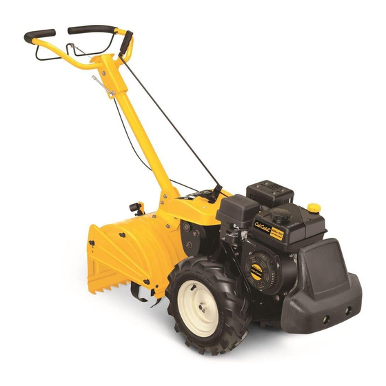
Rear Tine Tiller — RT65
WARNING
READ AND FOLLOW ALL SAFETY RULES AND INSTRUCTIONS IN THIS MANUAL
BEFORE ATTEMPTING TO OPERATE THIS MACHINE.
FAILURE TO COMPLY WITH THESE INSTRUCTIONS MAY RESULT IN PERSONAL INJURY.
CUB CADET LLC, P.O. BOX 361131 CLEVELAND, OHIO 44136-0019
Printed In USA
Form No. 769-05933
(February 22, 2010)
Advertisement
Table of Contents

Subscribe to Our Youtube Channel
Related Manuals for Cub Cadet RT65


Summary of Contents for Cub Cadet RT65
- Page 1 READ AND FOLLOW ALL SAFETY RULES AND INSTRUCTIONS IN THIS MANUAL BEFORE ATTEMPTING TO OPERATE THIS MACHINE. FAILURE TO COMPLY WITH THESE INSTRUCTIONS MAY RESULT IN PERSONAL INJURY. CUB CADET LLC, P.O. BOX 361131 CLEVELAND, OHIO 44136-0019 Printed In USA Form No. 769-05933...
-
Page 2: Table Of Contents
Visit us on the web at www.cubcadet.com ◊ Call a Customer Support Representative at (800) 965-4CUB ◊ Locate your nearest Cub Cadet Dealer at (877) 282-8684 ◊ Write us at Cub Cadet LLC • P.O. Box 361131 • Cleveland, OH • 44136-0019... -
Page 3: Important Safe Operation Practices
Important Safe Operation Practices WARNING! This symbol points out important safety instructions which, if not followed, could endanger the personal safety and/or property of yourself and others. Read and follow all instructions in this manual before attempting to operate this machine. Failure to comply with these instructions may result in personal injury. - Page 4 When practical, remove gas-powered equipment After striking a foreign object, stop the engine, disconnect from the truck or trailer and refuel it on the ground. the spark plug wire and ground against the engine. If this is not possible, then refuel such equipment on Thoroughly inspect the machine for any damage.
-
Page 5: Spark Arrester
Spark Arrester If the fuel tank has to be drained, do this outdoors. Observe proper disposal laws and regulations for gas, oil, WARNING! This machine is equipped with an etc. to protect the environment. internal combustion engine and should not be used According to the Consumer Products Safety Commission on or near any unimproved forest-covered, (CPSC) and the U.S. - Page 6 Safety Symbols This page depicts and describes safety symbols that may appear on this product. Read, understand, and follow all instructions on the machine before attempting to assemble and operate. Symbol Description READ THE OPERATOR’S MANUAL(S) Read, understand, and follow all instructions in the manual(s) before attempting to assemble and operate WARNING—...
-
Page 7: Assembly & Set-Up
Assembly & Set-Up Contents of Carton • One Tiller • One Handlebar Assembly • One Shift Rod • One Depth Stake • One Operator’s Manual • One Engine Operator’s Manual Assembly Depth Stake WARNING! Unpacking Instructions Before assembly, disconnect the spark plug wire and ground it against the engine to NOTE: References to the right or left side of the tiller are prevent unintended starting. - Page 8 Handlebar Assembly Remove the slot head screw, nut and two flat washers from the clutch bail. See Fig. 3-4. Remove the top two bolts and flange lock nuts from the handle mounting brackets, but do not remove the bottom Slot Head Screw bolt and nut.
- Page 9 Adjustments Control Rod Make sure the handle assembly is in the highest position. Clutch Cable Refer to the Controls & Features Section. NOTE: Service the engine with oil and gasoline before checking Remove the hairpin clips from the control rod, put the this adjustment.
- Page 10 Set-Up Tires The tires on your tiller may be over-inflated for shipping purposes. Reduce the tire pressure before operating the tiller. Recommended operating tire pressure is approximately 20 p.s.i. (check the sidewall of the tire for the manufacturer’s recommended pressure). WARNING! Maximum tire pressure under any circumstances is 30 p.s.i.
-
Page 11: Controls And Features
Controls and Features Gear Selection Handle Handle Adjustment Lock Clutch Control Depth Stake Figure 4-1 Engine Controls Choke Lever (If equipped) See the separate Engine Operator’s Manual for additional The choke lever is used to enrich the fuel mixture in the information and functions of the engine controls. -
Page 12: Operation
Operation Starting the Engine When using the tiller for the first time, use the second adjustment hole from the top (1” of tilling depth). See WARNING! Read, understand, and follow all the Figure 5-1. instructions and warnings on the machine and in this manual before operating. -
Page 13: Operating The Tiller
Operating the Tiller To adjust the side shields, remove the wing nuts. Move the side shield to the desired position and replace the wing Select the depth stake setting. nuts. Tighten securely. See Fig. 5-2. Start the engine as instructed in the Engine Operator’s Manual. -
Page 14: Maintenance & Adjustment
Maintenance & Adjustments Lubrication WARNING! Disconnect the spark plug wire and ground it against the engine before performing any Transmission maintenance or repairs. The transmission is pre-lubricated and sealed at the factory. It Maintenance requires no checking unless the transmission is disassembled. To fill with grease, lay the right half of the transmission on its side, Engine add 22 ounces of Benalene 920 grease, and assemble the left... - Page 15 Idler Pulley Rod After the belt tension has been adjusted, if the belt is excessively stretched, you may need to adjust the idler pulley rod. This can be checked easily. With the engine off and the clutch control bail disengaged, shift the gear selection handle to each forward mode.
-
Page 16: Engine Maintenance
Engine Maintenance Maintenance Schedule Each Use or Every Season Every Season Every Season Service First 5 Hours Every 5 Hrs. or 25 Hours or 50 Hours or 100 Hours Dates Check Engine Oil Level Change Engine Oil Check Air Cleaner Service Air Cleaner Check Spark Plug Replace Spark Plug... -
Page 17: Air Filter
20w40, 20w50 15w40, 15w50 10w40 10w30 (ºC) -30º -20º -10º 0º 10º 20º 30º 40º (ºF) -20º 0º 20º 40º 60º 80º 100º Drain Ambient Temperature Figure 6-1 Reinstall the drain plug and tighten it securely. Single Viscosity Refill with the recommended oil and check the oil level. Multi Viscosity Refer to the Assembly &... - Page 18 To clean foam element, separate it from the paper element Check that the spark plug washer is in good condition and wash in liquid detergent and water. Allow to dry and thread the spark plug in by hand to prevent cross- thoroughly before using.
- Page 19 Off-Season Storage Engines stored between 30 and 90 days need to be treated with a gasoline stabilizer and engines stored over 90 days need to be drained of fuel to prevent deterioration and gum from forming in fuel system or on essential carburetor parts. If the gasoline in your engine deteriorates during storage, you may need to have the carburetor, and other fuel system components, serviced or replaced.
-
Page 20: Service
Service Belt Replacement Remove the belt keeper assembly located behind the engine pulley by removing the two hex bolts and lock Your tiller has been engineered with a belt designed for long washers.. See Fig. 7-2. life and optimal performance. It should never be replaced with a non-OEM belt. -
Page 21: Troubleshooting
Troubleshooting Problem Cause Remedy Engine fails to start Fuel tank empty or stale fuel. Fill tank with clean, fresh gasoline. Throttle control lever not in correct starting Move throttle lever to start position. position (if equipped). Blocked fuel line. Clean fuel line. Dirty air cleaner. -
Page 22: Replacement Parts
Replacement Parts Component Part Number and Description 954-0434 Belt, 4L x 58.16 742-0305A-0637 Articulating Tine 946-1117 Clutch Cable 934-04365 Tires, 16 x 4.6 x 8 714-04043 Cotter Pin, Tine Assembly 911-0415 Clevis Pin, Tine Assembly 714-0147 Cotter Pin, Depth Stake 911-0415 Clevis Pin, Depth Stake 951-10794... - Page 23 Notes...
- Page 24 MANUFACTURER’S LIMITED WARRANTY FOR EDGERS, STRING TRIMMERS & TILLERS The limited warranty set forth below is given by Cub Cadet LLC with c. Cub Cadet does not extend any warranty for products sold or respect to new merchandise purchased and used in the United States,...
Need help?
Do you have a question about the RT65 and is the answer not in the manual?
Questions and answers
Where is the transmission oil fill plug on a RT 65 CUB CADET TILLER??? What type a weight of oil fill this transmission??