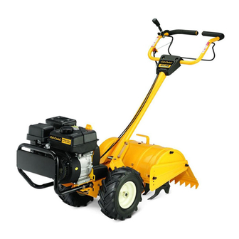
Cub Cadet RT 45 Operator's Manual
Rear tine tiller
Hide thumbs
Also See for RT 45:
- Operator's manual (32 pages) ,
- Parts manual (93 pages) ,
- Brochure & specs (2 pages)
Table of Contents
Advertisement
Available languages
Available languages
Safe Operation Practices • Set-Up • Operation • Maintenance • Service • Troubleshooting • Warranty
O
'
M
peratOr
s
anual
Rear Tine Tiller — Model RT 45
WARNING
READ AND FOLLOW ALL SAFETY RULES AND INSTRUCTIONS IN THIS MANUAL
BEFORE ATTEMPTING TO OPERATE THIS MACHINE.
FAILURE TO COMPLY WITH THESE INSTRUCTIONS MAY RESULT IN PERSONAL INJURY.
CUB CADET LLC, P.O. BOX 361131 CLEVELAND, OHIO 44136-0019
Printed In USA
Form No. 769-07570
(December 14, 2011)
Advertisement
Chapters
Table of Contents

Related Manuals for Cub Cadet RT 45


Summary of Contents for Cub Cadet RT 45
- Page 1 READ AND FOLLOW ALL SAFETY RULES AND INSTRUCTIONS IN THIS MANUAL BEFORE ATTEMPTING TO OPERATE THIS MACHINE. FAILURE TO COMPLY WITH THESE INSTRUCTIONS MAY RESULT IN PERSONAL INJURY. CUB CADET LLC, P.O. BOX 361131 CLEVELAND, OHIO 44136-0019 Printed In USA Form No. 769-07570...
-
Page 2: Table Of Contents
Visit us on the web at www.cubcadet.com See How-to Maintenance and Parts Installation Videos at www.cubcadet.com/tutorials ◊ Locate your nearest Cub Cadet Dealer at (877) 282-8684 ◊ Write to Cub Cadet LLC • P.O. Box 361131 • Cleveland, OH • 44136-0019... -
Page 3: Safe Operation Practices
Important Safe Operation Practices WARNING! This symbol points out important safety instructions which, if not followed, could endanger the personal safety and/or property of yourself and others. Read and follow all instructions in this manual before attempting to operate this machine. Failure to comply with these instructions may result in personal injury. - Page 4 When practical, remove gas-powered equipment After striking a foreign object, stop the engine, disconnect from the truck or trailer and refuel it on the ground. the spark plug wire and ground against the engine. If this is not possible, then refuel such equipment on Thoroughly inspect the machine for any damage.
- Page 5 Spark Arrestor If the fuel tank has to be drained, do this outdoors. Observe proper disposal laws and regulations for gas, oil, WARNING! This machine is equipped with an etc. to protect the environment. internal combustion engine and should not be used According to the Consumer Products Safety Commission on or near any unimproved forest-covered, (CPSC) and the U.S.
-
Page 6: Safety Symbols
Safety Symbols This page depicts and describes safety symbols that may appear on this product. Read, understand, and follow all instructions on the machine before attempting to assemble and operate. Symbol Description READ THE OPERATOR’S MANUAL(S) Read, understand, and follow all instructions in the manual(s) before attempting to assemble and operate WARNING—... -
Page 7: Assembly & Set-Up
Assembly & Set-Up Contents of Carton • One Tiller • One Handlebar Assembly • One Operator’s Manual • One Engine Operator’s Manual NOTE: This Operator’s Manual covers several models. Garden Install the handle-crank adjustment rod into the top hole of Tiller features may vary by model. - Page 8 Attaching the Cables Clip the cables into the cable guides located on the handle assembly panel as seen in Fig. 3-3. To attach the cables, follow these steps: Route the two cables along the handle assembly on the right-hand side. See Fig. 3-2. Black Black Figure 3-3...
- Page 9 Set-Up Remove the oil fill plug from the transmission housing cover and locate the main drive shaft situated inside the Tire Pressure housing. See Fig. 3-6. Check the air pressure with a tire gauge. Deflate or inflate the tires equally to between 15 and 20 PSI. DO NOT EXCEED 20 P.S.I. NOTE: Be sure that both tires are inflated equally or the tiller will pull to one side.
-
Page 10: Controls & Features
Controls & Features Reverse Handle Forward Clutch Bail & Tine Engagement Depth Regulator Handle Height Adjustment Rear Tine Shield Side Shield Tines Wheel Drive Pin Figure 4-1 Handlebar Height Adjustment NOTE: This Operator’s Manual covers several models. Garden Tiller features may vary by model. Not all features in this manual The handlebar height is adjustable to three different settings. -
Page 11: Operation
Operation Starting & Stopping the Engine WARNING: Before operating your machine, carefully read and understand this manual and all of Pre-Start Checklist its safety, operating and maintenance sections and instructions, along with all of the decals on the With the spark plug wire disconnected from the spark plug, machine. - Page 12 To Engage Drive & Tines To adjust the depth stake, pull back on the depth adjustment bracket (A) and push up or down (B) until the bracket reaches the For forward motion of the wheels and power to the tines pull desired position, see Fig.
- Page 13 Tilling Tips & Techniques Suggested Tilling Patterns • When preparing a seedbed, go over the same path twice in Tilling Depth the first row, then overlap one-half the tiller width on the rest of the passes. See Fig. 5-5. WARNING! Before tilling, contact your telephone or utilities company and inquire if underground equipment/ lines are used on your property.
- Page 14 Terrace Gardening • If the garden size will not permit lengthwise and then crosswise tilling, then overlap the first pass by one-half a To create a terrace, start at the top of the slope and work tiller width, followed by successive passes at one-quarter down.
- Page 15 Loading & Unloading the Tiller WARNING! Loading and unloading the tiller into a vehicle is potentially hazardous and doing so is not recommended unless absolutely necessary, as this could result in personal injury or property damage. However, if you must load or unload the tiller, follow the guidelines given next.
-
Page 16: Maintenance & Adjustments
Maintenance & Adjustments Maintenance Schedule Check After Every Every Every Before each use first 2 hours 5 Hours 10 Hours 30 Hours Clean Engine Check Drive Belt Tension Check Nuts and Bolts Lubricate Tiller Check Gear Oil Level in Transmission Check Tines for Wear Check Air Pressure in Tires WARNING! - Page 17 Off-Season Storage If adding only a few ounces of gear oil, use API rated GL-4 or GL-5 gear oil having a viscosity of SAE 140, SAE 85W-140 When the tiller won’t be used for an extended period, prepare it or SAE 80W-90. If refilling an empty transmission, use only for storage as follows: GL-4 gear oil having a viscosity of SAE 85W-140 or SAE 140.
-
Page 18: Service
Service Belt Replacement Remove the idler bracket extension spring, as pointed out in Fig. 7-3. It is recommended to use a pair of needle-nosed If the drive or reverse belts need to be replaced, it is best to replace pliers, and grab the spring by the end that hooks over the both belts at the same time. - Page 19 Removing/Installing a Tine Assembly Remove the flange nut securing the transmission drive pulley, then remove the pulley along with the two belts. Remove the tine shield end covers and side shields by See Fig. 7-5. removing the three wing nuts on each side that secure them.
-
Page 20: Troubleshooting
Troubleshooting Problem Cause Remedy Wheels/Tines will not turn 1. Improper use of controls. 1. Review Operation section. 2. Worn, broken, or misadjusted drive belt(s). 2. Replace or adjust belts. 3. Internal transmission wear or damage. 3. Contact authorized service dealer. 4. -
Page 21: Replacement Parts
Replacement Parts Component Part Number and Description 754-04090 Reverse V-Belt 754-04091 Forward V-Belt 946-04506 Forward Drive Cable 946-04504 Reverse Drive Cable 642-04072 4-Point Tine Assembly (RH) 642-04071 4-Point Tine Assembly (LH) 911-0415 Clevis Pin, .375 x 1.75 714-04043 Internal Cotter Pin 634-04736 Wheels, 13 x 5 x 6... - Page 22 Notes...
- Page 23 10 — n ection oteS...
-
Page 24: Warranty
MANUFACTURER’S LIMITED WARRANTY FOR EDGERS, STRING TRIMMERS & TILLERS The limited warranty set forth below is given by Cub Cadet LLC with c. Cub Cadet does not extend any warranty for products sold or respect to new merchandise purchased and used in the United States,... - Page 25 Medidas importantes de seguridad • Configuración • Funcionamiento • Mantenimiento • Servicio • Solución de problemas • Garantía aNual del operador Cultivadora de Dientes Frontales — Modelo RT 45 ADVERTENCIA LEA Y SIGA TODAS LAS INSTRUCCIONES DE ESTE MANUAL ANTES DE PONER EN FUNCIONAMIENTO ESTA MÁQUINA.
- Page 26 Visite nuestro sitio web en www.cubcadet.com Ver Vídeos demostrativos de instalación de mantenimiento y piezas en www.cubcadet.com/Tutorials ◊ Llame a un representante de Asistencia al Cliente al (800) 965-4CUB ◊ Escríbanos a Cub Cadet LLC • P.O. Box 361131 • Cleveland, OH • 44136-0019...
-
Page 27: Importante Medidas Importantes De Seguridad
Medidas importantes de seguridad ¡ADVERTENCIA! La presencia de este símbolo indica que se trata de instrucciones importantes de seguridad que se deben respetar para evitar poner en peligro su seguridad personal y/o material y la de otras personas. Lea y siga todas las instrucciones de este manual antes de poner en funcionamiento esta máquina. - Page 28 Manejo seguro de la gasolina: Tenga cuidado cuando labre tierras duras. Los dientes pueden clavarse en la tierra e impulsar la cultivadora Para evitar lesiones personales o daños materiales tenga mucho hacia adelante. Si esto ocurre, suelte el manubrio y deje la cuidado cuando trabaje con gasolina.
- Page 29 Aviso referido a emisiones Antes de limpiar, reparar o inspeccionar la máquina, detenga el motor y asegúrese de que los dientes y todas las partes móviles se hayan detenido. Desconecte el cable Los motores que están certificados y cumplen con las de la bujía y póngalo haciendo masa contra el motor para regulaciones de emisiones federales EPA y de California para evitar que se encienda accidentalmente.
- Page 30 Símbolos de Seguridad Esta página describe los símbolos y figuras de seguridad internacionales que pueden aparecer en este producto. Lea el manual del operador para obtener la información terminada sobre seguridad, reunirse, operación y mantenimiento y reparación. Símbolo Descripción LEA EL MANUAL DEL OPERADOR (S) Lea, entienda, y siga todas las instrucciones en el manual (es) antes de intentar reunirse y funcionar.
-
Page 31: Ensamblado Y Configuración
Montaje y Configuración Contenido de la caja • Una Cultivadora • Un Montaje De Las Barras De Control • Un Manual Del Operador • Un Paquete De Hardware • Un Motor Manual Del Usuario • Un 20 Oz Botella De Aceite Sae 10w30 ¡ADVERTENCIA! Para evitar lesiones personales o Instale la varilla de ajuste de la manivela en el orificio... - Page 32 Unión de los cables Clip de los cables en las guías de cable situado en el panel conjunto de la palanca como se ve en la fig. 3-3. Delante del Embrague por Cable Pase los dos cables a lo largo del conjunto de la palanca en el lado derecho.
- Page 33 Configuración Retire el tapón de llenado de aceite de la tapa de la caja de transmisión y localizar el eje principal situado en el interior Presión de los neumáticos de la vivienda. Vea Fig. 3.6. Verifique la presión de aire con un manómetro para neumáticos. Infle o desinfle los neumáticos en forma uniforme entre 15 y 20 PSI.
-
Page 34: Controles Y Características
Controles y Características Manija de marcha atrás Gancho del embrague de marcha directa y engranaje de dientes. Regulador de profundidad Ajuste de la altura de la manija Protector de dientes trasero Side Shield Dientes Pasador de transmisión en las ruedas Figura 4-1 Protector lateral NOTA: Este manual del operador cubre varios modelos de... -
Page 35: Funcionamiento
Funcionamiento Arranque y detención del motor ¡ADVERTENCIA! Antes de hacer funcionar la máquina, lea con atención este manual y todas Lista de verificación previa al arranque las instrucciones de las secciones de seguridad, funcionamiento y mantenimiento, además de todas Con el cable de la bujía desconectado de la bujía, realice los las calcomanías que se encuentran en la máquina. - Page 36 Procedimiento para engranar la transmisión y los dientes Establecimiento de la profundidad Para mover las ruedas hacia adelante e impulsar los La profundidad de labranza está controlada por la estaca dientes coloque el gancho del embrague de marcha directa de profundidad que se puede regular en cinco posiciones contra la barra de control.
- Page 37 Ajuste de la altura de la manija • Al realizar tareas de labranza (rompiendo la superficie de suelo alrededor de las plantas para destruir las malezas, vea la Fig. 5-4), ajuste los dientes para cavar únicamente a La manija debe ajustarse para que cuando la cultivadora esté una profundidad de 1”...
- Page 38 Modelos de labranza sugeridos • Si las dimensiones del jardín no permiten la labranza en sentido longitudinal y luego en sentido transversal, • Al preparar el lecho de siembra, recorra la misma senda dos traslape las primeras pasadas por la mitad del ancho de veces en la primera hilera, luego traslape la mitad del ancho la cultivadora, continuando con sucesivas pasadas a un de la cultivadora en el resto de las pasadas.
- Page 39 Jardinería en terrazas Carga y descarga de la cultivadora Para crear una terraza, comience en la cima de la pendiente ¡ADVERTENCIA! La carga y descarga de la y trabaje hacia abajo. Recorra la primera hilera hacia atrás y cultivadora en un vehículo es potencialmente hacia adelante como se muestra en la Fig.
-
Page 40: Mantenimiento Y Ajustes
Mantenimiento y Ajustes Calendario de mantenimiento Verifique después de las primeras 2 Antes de cada uso Cada 5 horas Cada 10 horas Cada 30 horas horas Verifique la tensión de la correa de transmisión Verifique las tuercas y los pernos Lubrique la cultivadora Verifique el nivel de aceite de engranajes de la transmisión... - Page 41 Almacenamiento fuera de temporada El nivel de aceite de engranajes es correcto si el aceite del cambio es de aproximadamente la mitad de la cara del eje Si la cultivadora no se va a usar durante un período prolongado, principal. prepárela para el almacenamiento de la siguiente forma: Si el nivel de aceite en el cambio está...
-
Page 42: Servicio
Servicio Cambio de correa Saque los cuatro tornillos hexagonales autorroscantes de 1/4-20 que aseguran el protector de la polea al bastidor Si es necesario reemplazar la correa de transmisión o las correas como se ve en la Fig. 7-2, retire el protector de la polea y de barrenas, conviene reemplazar ambas al mismo tiempo. - Page 43 Retire el soporte de la polea loca sacando el tornillo Vuelva a armar la cultivadora en el orden inverso a como de cabeza hexagonal de 5/16-24, la arandela plana y la fue desarmada. arandela de seguridad, como en la Fig. 7-4. NOTA: Cuando reinstale la cubierta de la correa, asegúrese de acoplar el gancho y retenerlo para que la correa de transmisión esté...
- Page 44 Antes de volver a instalar el conjunto de dientes, inspeccione el eje de los dientes para verificar si esta oxidado, tiene asperezas o rebabas. Lime o lije ligeramente, según sea necesario. Aplique al eje una capa delgada de grasa. Instale cada conjunto de dientes de modo que el borde cortante (afilado) de los dientes se introduzca en el suelo primero cuando la cultivadora se mueva hacia adelante.
-
Page 45: Solución De Problemas
Solución de Problemas Problema Causa Solución Las ruedas y los dientes no giran 1. Uso incorrecto de los controles. 1. Revise la sección de Funcionamiento 2. Correa(s) de transmisión desgastada(s), rota(s) o mal 2. Reemplace o ajuste las correas. ajustada(s). 3. - Page 46 Notas...
- Page 47 9 — n ection otaS...
- Page 48 Cub Cadet para su uso con el o los productos con respecto a los productos, obligará a Cub Cadet. Durante el incluido(s) en este manual anulará...
Need help?
Do you have a question about the RT 45 and is the answer not in the manual?
Questions and answers