Cub Cadet RT 65 Operator's Manual
Rear tine
Hide thumbs
Also See for RT 65:
- Parts manual (41 pages) ,
- Illustrated parts manual (24 pages) ,
- Operator's manual (24 pages)
Table of Contents
Advertisement
Available languages
Available languages
Safe Operation Practices • Set-Up • Operation • Maintenance • Service • Troubleshooting • Warranty
O
'
M
peratOr
s
anual
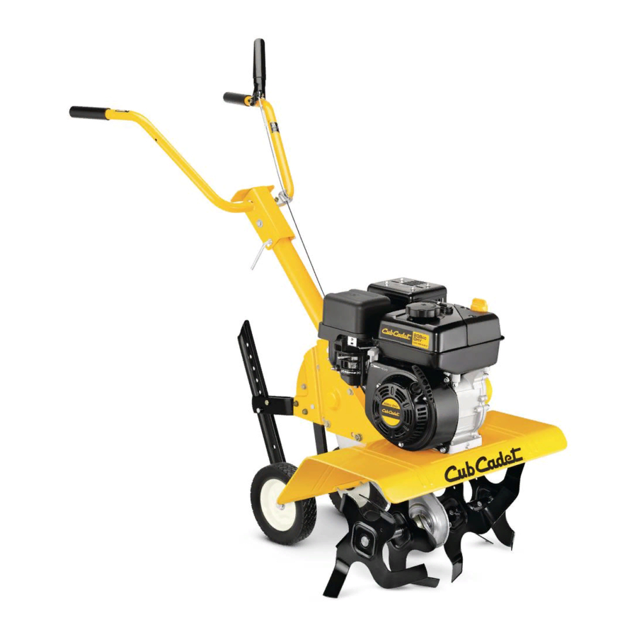
Rear Tine Tiller — Model RT 65
WARNING
READ AND FOLLOW ALL SAFETY RULES AND INSTRUCTIONS IN THIS MANUAL
BEFORE ATTEMPTING TO OPERATE THIS MACHINE.
FAILURE TO COMPLY WITH THESE INSTRUCTIONS MAY RESULT IN PERSONAL INJURY.
CUB CADET LLC, P.O. BOX 361131 CLEVELAND, OHIO 44136-0019
Printed In USA
Form No. 769-07317A
(October 31, 2011)
Advertisement
Chapters
Table of Contents

Related Manuals for Cub Cadet RT 65


Summary of Contents for Cub Cadet RT 65
- Page 1 READ AND FOLLOW ALL SAFETY RULES AND INSTRUCTIONS IN THIS MANUAL BEFORE ATTEMPTING TO OPERATE THIS MACHINE. FAILURE TO COMPLY WITH THESE INSTRUCTIONS MAY RESULT IN PERSONAL INJURY. CUB CADET LLC, P.O. BOX 361131 CLEVELAND, OHIO 44136-0019 Printed In USA Form No. 769-07317A...
-
Page 2: Table Of Contents
Choose from the options below: ◊ Visit us on the web at www.cubcadet.com ◊ Locate your nearest Cub Cadet Dealer at (877) 282-8684 ◊ Write us at Cub Cadet LLC • P.O. Box 361131 • Cleveland, OH • 44136-0019... -
Page 3: Important Safe Operation Practices
Important Safe Operation Practices WARNING! This symbol points out important safety instructions which, if not followed, could endanger the personal safety and/or property of yourself and others. Read and follow all instructions in this manual before attempting to operate this machine. Failure to comply with these instructions may result in personal injury. - Page 4 When practical, remove gas-powered equipment After striking a foreign object, stop the engine, disconnect from the truck or trailer and refuel it on the ground. the spark plug wire and ground against the engine. If this is not possible, then refuel such equipment on Thoroughly inspect the machine for any damage.
- Page 5 Spark Arrestor If the fuel tank has to be drained, do this outdoors. Observe proper disposal laws and regulations for gas, oil, WARNING! This machine is equipped with an etc. to protect the environment. internal combustion engine and should not be used According to the Consumer Products Safety Commission on or near any unimproved forest-covered, (CPSC) and the U.S.
- Page 6 Safety Symbols This page depicts and describes safety symbols that may appear on this product. Read, understand, and follow all instructions on the machine before attempting to assemble and operate. Symbol Description READ THE OPERATOR’S MANUAL(S) Read, understand, and follow all instructions in the manual(s) before attempting to assemble and operate WARNING—...
-
Page 7: Assembly & Set-Up
Assembly & Set-Up Contents of Carton • One Tiller • One Handlebar Assembly • One Shift Rod • One Depth Stake • One Operator’s Manual • One Engine Operator’s Manual NOTE: This Operator’s Manual covers several models. Garden Depth Stake tiller features may vary by model. -
Page 8: Handle
Handle Push the cable through the hole in the center of the handle and snap into the plastic fitting. See Fig. 3-4. Remove the top two hex screws and flange lock nuts from the handle mounting brackets, but do not remove the bottom hex screw and flange lock nut. - Page 9 Set-Up Control Rod Make sure the handle assembly is in the highest position. Tires Refer to the Controls & Features section. The tires on the tiller may be over-inflated for shipping Remove the cotter pins from the control rod, leave the purposes.
- Page 10 Carefully engage the clutch by lifting the clutch control Handle bail against the handle. The wheels should spin. If the The handle should be adjusted so that when the tiller is digging wheels do not spin with the tiller in forward, adjust by 3-4”...
-
Page 11: Controls & Features
Controls & Features Gear Selection Handle Handle Adjustment Lock Clutch Control Depth Stake Shift Lever Indicator Figure 4-1 Clutch Control NOTE: This Operator’s Manual covers several models. Garden tiller features may vary by model. Not all features in this manual The clutch control is located beneath the handle. -
Page 12: Operation
Operation Starting the Engine When breaking up sod and for shallow cultivation, use the setting which gives 1” of tilling depth (second hole from the top). Place the side shields in their lowest position. See Fig. 5-2. WARNING! Read, understand, and follow all instructions and warnings on the machine and in Use This Hole for this manual before operating. -
Page 13: Operating The Tiller
Operating the Tiller Select the depth stake setting. Start the engine as instructed on the previous page. Move the gear selection handle to one of the forward modes or reverse. WARNING! Do not move the gear selection handle with the wheels or tines engaged. Make certain the tiller is stopped completely before changing the gear selection. -
Page 14: Maintenance & Adjustments
Maintenance & Adjustments Adjustments WARNING! Disconnect the spark plug wire and ground it against the engine before performing any WARNING! Never attempt to make any maintenance or repairs. adjustments while the engine is running, except Maintenance where specified in the Operator’s Manual. Engine Adjustment Engine Refer to the separate Engine Operator’s Manual for engine... -
Page 15: Service
Service NOTE: This Operator’s Manual covers several models. Garden Remove the belt keeper assembly located behind the tiller features may vary by model. Not all features in this manual engine pulley by removing the two hex bolts and lock are applicable to all garden tiller models and the garden tiller washers.. -
Page 16: Secondary Cable Adjustment
Secondary Cable Adjustment If additional adjustment is necessary after the primary adjustment can no longer be used, the secondary adjustment can be performed as follows: Remove the belt cover as instructed the Belt Replacement section above. Locate the spring at the end of the cable. See Fig. 7-3. Upper Nut Lower Nut Idler Pulley Bracket... -
Page 17: Troubleshooting
Troubleshooting Problem Cause Remedy Tines do not engage 1. Foreign object lodged in tines. 1. Dislodge foreign object. 2. Tine clevis pin(s) missing. 2. Replace tine clevis pin(s). 3. Pulley and idler not in correct adjustment. 3. Take tiller to authorized service dealer. 4. -
Page 18: Replacement Parts
Cotter Pin, Tine Assembly 911-0415 Clevis Pin, Tine Assembly 714-0147 Cotter Pin, Depth Stake 911-0415 Clevis Pin, Depth Stake 951-10794 Air Filter (Cub Cadet Engine) 17211-ZL8-023 Air Filter (Honda Engine) 951-10292 Spark Plug (Cub Cadet Engine) 98079-56846 Spark Plug (Honda Engine) (800) 965-4CUB... - Page 19 Notes...
-
Page 20: Warranty
MANUFACTURER’S LIMITED WARRANTY FOR EDGERS, STRING TRIMMERS & TILLERS The limited warranty set forth below is given by Cub Cadet LLC with c. Cub Cadet does not extend any warranty for products sold or respect to new merchandise purchased and used in the United States,... - Page 21 Medidas importantes de seguridad • Configuración • Funcionamiento • Mantenimiento • Servicio • Solución de problemas • Garantía aNual del operador Cultivadora de Dientes Traseros — Modelo RT 65 ADVERTENCIA LEA Y SIGA TODAS LAS INSTRUCCIONES DE ESTE MANUAL ANTES DE PONER EN FUNCIONAMIENTO ESTA MÁQUINA.
- Page 22 Elija entre las opciones que se presentan a continuación: ◊ Visite nuestro sitio web en www.cubcadet.com ◊ Llame a un representante de Cub Cadet Dealer at (877) 282-8684 ◊ Escríbanos a Cub Cadet LLC • P.O. Box 361131 • Cleveland, OH • 44136-0019...
-
Page 23: Importante Medidas Importantes De Seguridad
Medidas importantes de seguridad ¡ADVERTENCIA! La presencia de este símbolo indica que se trata de instrucciones importantes de seguridad que se deben respetar para evitar poner en peligro su seguridad personal y/o material y la de otras personas. Lea y siga todas las instrucciones de este manual antes de poner en funcionamiento esta máquina. - Page 24 Manejo seguro de la gasolina: Tenga cuidado cuando labre tierras duras. Los dientes pueden clavarse en la tierra e impulsar la cultivadora Para evitar lesiones personales o daños materiales tenga mucho hacia adelante. Si esto ocurre, suelte el manubrio y deje la cuidado cuando trabaje con gasolina.
- Page 25 Aviso referido a emisiones Antes de limpiar, reparar o inspeccionar la máquina, detenga el motor y asegúrese de que los dientes y todas las partes móviles se hayan detenido. Desconecte el cable Los motores que están certificados y cumplen con las de la bujía y póngalo haciendo masa contra el motor para regulaciones de emisiones federales EPA y de California para evitar que se encienda accidentalmente.
- Page 26 Símbolos de Seguridad Esta página describe los símbolos y figuras de seguridad internacionales que pueden aparecer en este producto. Lea el manual del operador para obtener la información terminada sobre seguridad, reunirse, operación y mantenimiento y reparación. Símbolo Descripción LEA EL MANUAL DEL OPERADOR (S) Lea, entienda, y siga todas las instrucciones en el manual (es) antes de intentar reunirse y funcionar.
-
Page 27: Ensamblado Y Configuración
Montaje y Configuración El Contenido del Cartón • Un Cultivadora • Un Unidad de la Manija • Un Varilla de control • Un Depth Stake • Un Manual de Operario • Un Manual de Operario de Motor NOTA: Este Manual abarca varios modelos. características Jardín Estaca de profundidad caña puede variar según el modelo. - Page 28 Manija Empuje el cable a través del orificio del centro de la manija e introduzca a presión el accesorio plástico. Vea la Fig. 3-4. Retire los dos tornillos de cabeza hexagonal y tuercas de bloqueo de los soportes de montaje de la manija, pero no quite el tornillo hexagonal final y la tuerca de la brida.
- Page 29 Configuración Varilla de Control Asegúrese de que la unidad de la manija esta en la posición Neumáticos más alta. Consulte la sección Conozca la cultivadora. Tal vez los neumáticos de la unidad hayan sido inflados en exceso Retire los broches de horquilla de la varilla de control (las para el envío del producto.
- Page 30 Manejar Cuidadosamente el embrague mediante el levantamiento de la fianza de control de embrague contra el larguero. Las El mango debe ser ajustado de manera que cuando la caña está ruedas deben girar. Si las ruedas no giran con el timón en cavando 3-4“en el suelo, el mango cae sobre los residuos de adelante, ajuste de la ONU-threading el tubo en el extremo alta.
-
Page 31: Controles Y Características
Controles y Características Manija selectora de cambios Traba de ajuste de la manija Control de embrague Estaca de Cambie de puesto profundidad el indicador de la palanca Figura 4-1 Control de embrague NOTA: Este Manual abarca varios modelos. características Jardín caña puede variar según el modelo. -
Page 32: Funcionamiento
Funcionamiento Encendido del motor Al romper el césped y para el cultivo poco profundo, utilice la configuración que le da una “profundidad de la labranza (segundo agujero desde la parte superior). Coloque los ¡ADVERTENCIA! Lea, comprenda y siga todas las protectores laterales en su posición más baja. - Page 33 Funcionamiento de la Cultivadora Seleccione la posición de la estaca de profundidad. Arranque el motor según las instrucciones de la página anterior. Mueva la manija selectora de cambios a uno de los modos de marcha directa o marcha atrás.. ¡ADVERTENCIA! No mueva la manija selectora de cambios con las ruedas o dientes enganchados.
-
Page 34: Mantenimiento Y Ajustes
Mantenimiento y Ajustes Ajustes ¡ADVERTENCIA! Desconecte el cable de la bujía y póngalo haciendo masa contra el motor antes de ¡ADVERTENCIA! NUNCA intente realizar ningún tipo realizar cualquier reparación. de ajuste mientras el motor está encendido, excepto si así lo especifica el Manual de Operario de Motor. Mantenimiento Ajuste del motor Motor... - Page 35 Mueva la varilla de la polea loca al orificio más bajo de la ménsula intermedia. Vuelva a colocar la arandela de resorte y el broche de horquilla. Compruebe el espacio libre entre la varilla de la polea loca y el soporte del indicador cambiando a cada una de las marchas directas, como anteriormente.
-
Page 36: Servicio
Servicio NOTA: Este Manual abarca varios modelos. características Jardín Retire la ménsula del guardacorrea ubicado detrás de la caña puede variar según el modelo. No todas las características polea del motor extrayendo dos pernos hexagonales y de este manual son aplicables a todos los modelos de jardín arandelas de seguridad. - Page 37 Ajuste del cable del secundario Si el ajuste adicional es necesaria después de que el ajuste primario no puede ser utilizado, el ajuste secundario se puede realizar de la siguiente manera: Retire la tapa de la correa como se indica la sección Reemplazo de la correa por encima.
-
Page 38: Solución De Problemas
Solución de Problemas Problema Causa Solución Los dientes no enganchan 1. Hay un objeto extraño entre los dientes. 1. Desaloje el objeto extraño. 2. Falta la o las chavetas de horquilla de los 2. Cambie la o las chavetas de horquilla de los dientes. - Page 39 Notas...
- Page 40 Cub Cadet para su uso con el o los productos con respecto a los productos, obligará a Cub Cadet. Durante el incluido(s) en este manual anulará...
Need help?
Do you have a question about the RT 65 and is the answer not in the manual?
Questions and answers
When I put the tiller in neutral it won't roll forward or backwards
The Cub Cadet RT 65 tiller won't roll forward or backward when in neutral because, in that gear position, none of the drive gears are engaged. As described, when the tiller is in neutral, only the shaft turns while the internal gears do not move, preventing the wheels from rotating.
This answer is automatically generated
tiller will not shift into reverse
The gear shifter is stuck and won’t move either way. It appears to be stuck in reverse but don’t know for sure. How can I get it to shift?