Table of Contents
Advertisement
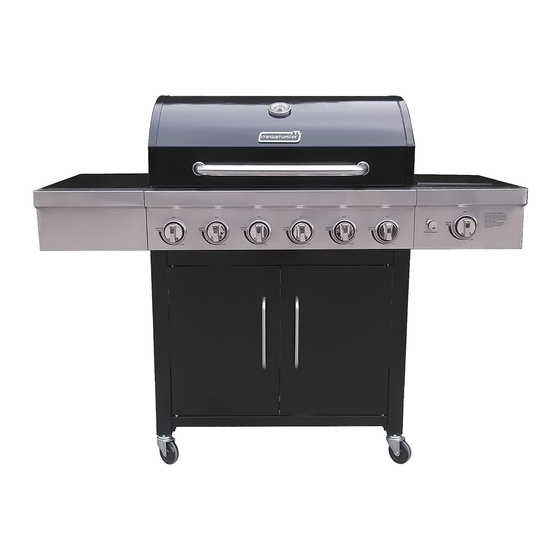
USER MANUAL & ASSEMBLY INSTRUCTIONS
Important: Read these instructions and warnings carefully so as to familiarize yourself with the
appliance before connecting it to its gas container. Keep these instructions for future reference.
LPGSASA Permit Number (1185-11/2-RSA-12A)
Manufactured in China· Distributed by Mega Group · PO Box 15, Woodlands, 0027, South Africa· Tel: +27(0)12 802 1515
WARNING
To reduce the risk of fire,burn hazard or
other injury,read the manual carefully and
completely before using your grill.
WARNING
This grill is not intended to be
installed in or on recreational vehicles
and/or boats.
Blaze 600 Black
www.megamaster.co.za
f
WARNING
d
FOR OUTDOOR USE ONLY
.
Advertisement
Table of Contents

Subscribe to Our Youtube Channel
Related Manuals for Megamaster Blaze 600 Black


Summary of Contents for Megamaster Blaze 600 Black
- Page 1 Blaze 600 Black USER MANUAL & ASSEMBLY INSTRUCTIONS Important: Read these instructions and warnings carefully so as to familiarize yourself with the appliance before connecting it to its gas container. Keep these instructions for future reference. LPGSASA Permit Number (1185-11/2-RSA-12A) www.megamaster.co.za...
-
Page 2: Table Of Contents
Table of Contents Safety Instructions Operating Instructions Package Contents List Braai ignition Instructions 30-31 Hardware Contents Care and Maintenance Exploded View Trouble Shooting Part List 12-13 Warranty Information Assembly Instructions 14-26 Gas Hook –Up Installer Final Check List Leak Testing 28-29 Safety Instructions DANGER... -
Page 3: Safety Instructions
Safety Instructions DANGER Never leave the braai unattended while it is on. Never operate this appliance within 10 ft (3 m) of any structure, combustible material or other LP gas cylinder. Never operate this appliance within 25 ft (7.5 m) of any flammable substance. Do not fill cooking vessel beyond maximum fill line. - Page 4 Safety Instructions WARNING CAUTION: Beware of Burn-Back Do not try lighting this appliance without reading the “LIGHTING INSTRUCTIONS” section of this manual CAUTION: Spiders and small insects occasionally spin webs or make nests in the braai burner tubes during transit and warehousing.
- Page 5 Safety Instructions LP-Gas Supply System • When your gas braai is not in use the gas must be turned off at LP gas cylinder. • If this information is not followed exactly, a fire • The gas must be turned off at the supply cylinder resulting in death or serious injury could occur.
- Page 6 Safety Instructions PROPER PLACEMENT AND CLEARANCE OF BRAAI CAUTION: TO ENSURE CONTINUED PROTECTION AGAINST RISK OF ELECTRIC • Never use your gas braai in a garage, porch, shed, SHOCK, CONNECT TO PROPERLY or any other enclosed area. Your gas braai is to be GROUNDED OUTLETS ONLY.
- Page 7 Safety Instructions Keep the area surrounding the braai free from Do not heat unopened food containers on the braai. combustible materials including, fluids, trash and A build-up of pressure may cause the containers vapours such as gasoline or charcoal lighter fluid. Do to burst.
-
Page 8: Package Contents List
Package Contents List C. Cart leg front,right -- A. Cart leg front,left--- B. Cart leg rear,left --- -1pc D. Cart leg rear,right D.Cart leg rear,right E. Swivel caster --- F. Swivel caster with 2pcs brake---2pcs I. Bottom panel ---1pc G. Side panel---3pcs H. - Page 9 Package Contents List S.Side burner,right --- T. Side burner end U. Side shelf---1pc cap,right --- 1pc V. Side shelf end X.Side tube burner --- W. Triangle braket for cap,left ---1pc side shelf ---2pcs Y.Control knob ---1pc Z.Pulse igniter module AA.Grease tray---1pc AB.Grease try support AC.Grease try support AD.
-
Page 10: Hardware Contents
Hardware Contents REF# Description Specification Quantity Truss Head Screw 1/4-20x3/5’’ 14PCS Truss Head Screw 5/32-32x2/5’’ 18PCS Flat Washer 1/4” 6PCS Flat Washer 5/32” 4PCS... -
Page 11: Exploded View
Exploded view... -
Page 12: Part List
Part List Warranty Warranty coverage coverage Part (Description) Part (Description) (year) (year) Main lid Main manifold Main lid screw Side burner flex gas line Main lid handle Side burner gas valve Temperature gauge Side manifold Temperature gauge seat Regulater,LP Logo Main control panel Hood buffer A Bezel... - Page 13 Part List Warranty Warranty Part (Description) coverage Part (Description) coverage (year) (year) Pulse igniter module Cart leg front,right Side burner igniter wire Cart leg rear,right Triangle bracket,right Swivel caster with brake Triangle bracket,left Swivel caster Side panel Door, right Side panel right,top Door, left Bottom panel Door handle...
-
Page 14: Assembly Instructions
Assembly Instructions Fig. 1 Cart Caster and Cart Assembly Loosen, but do not remove the screws that are pre- assembled on the Cart Leg Rear Left (B) and Cart Leg Front Left (A). Attach Cart Leg Rear Left (B) and Cart Leg Front Left (A) to Side panel (G)by aligning the holes on the Side Panel(G).Tighten the screws that were loosened above.As shown in Fig.1. - Page 15 Assembly Instructions Loosen, but do not remove the screws that are Fig. 4 pre- assembled on the Cart Leg Rear Leg Right(D) and Cart Leg Front Right (C). Attach Cart Leg Rear Right(D) and Cart Leg Front Right (C) to Side panel,Top (H)by aligning the holes on the Side Panel,Top(H).Tighten the screws that were loosened above.As shown in Fig.4.
- Page 16 Assembly Instructions Fig. 7 c) Loosen but do not remove the screws that were pre-assembled on the Cart Leg Front Left(A) and Cart Leg Front Right(C), Attach Cart Leg Front Left (A) and Cart Leg Front Right (C) to Cart Frame (N), by aligning the holes on the Cart Frame.Then tighten the screws that are loosed before.As shown in Fig.7.
- Page 17 Assembly Instructions Fig. 10 5. Door Assembly a) Loosen but do not remove the screws that were pre-assembled on the Bottom Panel (I),Attach Door iron piece(K), Tighten the screws that were loosened above.As .As shown in Fig.10. Fig. 11 b) Unscrew the screws that were pre-assembled on the Door handle(Q),Attach Door handle(Q) onto the Door Left (O) and Door Right (P).Tighten the screws that were unscrew above.As shown in Fig.11.
- Page 18 Assembly Instructions 6. Firebox Assembly Fig. 13 a) Move the firebox Asssembly (R) from the carton and carefully place onto the grill cart.Lid handle will face front and be above front panel.As shown in Fig.13. NOTE:The firebox assembly is heavy and will require two or more people to lift and position onto grill cart.Failure to do so may result in injury.Be sure to remove all packaging material during...
- Page 19 Assembly Instructions Fig. 16 Using 2 pcs Truss Head Screw (B) to connect Bx 2 Side shelf end cap,left (V) and side shelf (U) .As shown in Fig.16. Fig. 17 Bx 2 Using 2 pcs Truss Head Screw (B) to connect Triangle braket for side shelf (V) and side shelf (U).As shown in Fig.17.
- Page 20 Assembly Instructions Fig. 19 e) Using 3pcs Truss Head Screw (A) and 3 pcs flat Ax 3 washer (C) to connect left side shelf and firebox Cx 3 assembly (R),Using 1pcs Truss Head Screw (B) Bx 1 to connect Side shelf front panel,left and main control panel.
- Page 21 Assembly Instructions Fig. 22 c) Using 2 pcs Truss Head Screw (B) to connect Bx 2 Side burnder end cap,right(T) and side burner,right (S)).As shown in Fig.22. d) Loosen but do not remove the 2 pcs screws that Fig. 23 were pre-assembled on the firebox assembly (R) right side,attached right side burner onto the firebox, Tighten the screws that were loosened...
- Page 22 Assembly Instructions Fig. 25 Loosen the screws which pre-assembled on the side burner gas valve then align the screws to the valve with the large side of the holes on the bezel,fix with vertical gourd holes,then tighten the screws.As shown in Fig. 25. Insert Control Knob (Y) into the valve setem and tightenit.As shown in Fig.26 Fig.
- Page 23 Assembly Instructions 9. Pulse Igniter Module and Battery Assembly Fig. 28 Remove igniter battery cap and lock washer from igniter.Insert Pulse Igniter Module (Z)throuth from back of side burner control panel,secure lock washer from front of side burner control panel.Then insert the ignition wires to the Pulse Ignition Module (Z) located on the right side burner control panel.As shown in Fig.
- Page 24 Assembly Instructions Fig. 31 Bx 4 Grease Tary and Grease Box installation Dx 4 Attached Grease Cup Support Bracket A(AB) to Grease Tray(AA) by using 2pcs Truss Head Screw(B) and 2 pcs Flat Washers (D).As shown in Fig.31.As shown in Fig.31. Fig.
- Page 25 Assembly Instructions Fig. 34 d) Install the Grease Tray (AA) from the rear of the grill by sliding the tray on the glides at the rear of the grill until centered under the cooking area.As shown in Fig. 34. Fig. 35 e) Install the Grease Box (AE) under the Grease Tray(AA).As shown in Fig.35.
- Page 26 Assembly Instructions Fig. 37 b) Place the Cooking Grids (AG) into the grill. As shown in Fig.37. Fig. 38 c) Insert legs of Warming Rack (AH) into the holes on the top of firebox side panels.Place Side Burnder Cooking Grid (AI) into the side burner.As shown in Fig.38.
-
Page 27: Gas Hook-Up
Gas Hook-up NEVER CONNECT AN UNREGULATED GAS Regulator Connection SUPPLY LINE TO THE APPLIANCE. USE THE REGULATOR/HOSE ASSEMBLY SUPPLIED. This is a LP Gas configured braai. Do not attempt to use a natural gas supply unless the braai has been reconfigured for natural gas use. -
Page 28: Installer Final Check List
Installation final check list Minimum clearance from the sides and back of USER, PLEASE RETAIN THIS MANUAL FOR the unit to combustible constructions is, 61cm FUTURE REFERENCE. from the sides and 61cm from the back. LP GAS CYLINDER CAUTIONS ... - Page 29 Leak Test CAUTION Place dust cap on cylinder valve outlet when the cylinder is not in use. Only install the type of dust cap on the cylinder valve outlet that is provided with the cylinder valve. Other types of caps or plugs may result in leaking of LP gas.
-
Page 30: Operating Instructions
Operating Instructions Using the braai NOTE: The hot braai sears the food, sealing in the juices. The more thoroughly the braai is preheated, the Each main burner is rated at 12,000 Btu/hr. The main faster the meat browns and the darker the braai marks. braai burners encompass the entire cooking area and are side ported to minimize blockage from falling DO NOT LEAVE THE BRAAI UNATTENDED WHILE... - Page 31 Braai ignition instructions Flame characteristics Check for proper burner flame characteristics. Burner flames should be blue and stable with no yellow tips, excessive noise, or lifting. If any of these conditions Visually check the burner flames prior to each exist call our customer service line. If the flame is yellow, use, The flames should look like this picture, if this is a indication of insufficient air.
-
Page 32: Care And Maintenance
Care and maintenance Stainless steel Warning: If you wish to replace the main burner, we strongly recommend that you hire a There are many different stainless steel cleaners available. professionally trained technician to replace it. Always use the mildest cleaning procedure first, scrubbing in Please understand that we will not be responsible the direction of the grain. -
Page 33: Trouble Shooting
Trouble shooting Spider and insect warning Checking and cleaning burner/ venturi tubes for insects and insect nests. A clogged tube can lead to a fire beneath the braai. Spiders and small insects occasionally spin webs or make nests in the braai burner tubes during transit and warehousing. These webs can lead to gas flow obstruction which could result in a fire in and around burner tubes. - Page 34 Trouble shooting PROBLEM SOLUTION When attempting to light my braai, it will Make sure you have a spark while you are trying to ignite the burner not light immediately. If there is no spark: -Ensure that the wire is connected to the electrode assembly. -Clean wire (s) and / or electrode with rubbing alcohol and a clean swab.
-
Page 35: Warranty Information
Warranty information This braai has a one (1) year limited warranty. The warranty period is valid from the date of purchase. Please retain your proof of purchase. This is subject to correct assembly, use, storage and regular maintenance of the product. - Page 36 Blaze 600 Black FOR OUTDOOR USE ONLY WARNING Read and follow all Safety, Assembly, and Use & Care Instructions in this guide before assembling and cooking with this grill. Failure to follow all instructions in this Use & Care Guide may lead to fire or explosion, which could result in property damage,personal injury or death.
Need help?
Do you have a question about the Blaze 600 Black and is the answer not in the manual?
Questions and answers