
Related Manuals for CTC Union FTH4-1000MS


Summary of Contents for CTC Union FTH4-1000MS
-
Page 1: User Manual
USER MANUAL FTH4-1000M(S) FTH4-100M Managed Gigabit & Fast Ethernet OAM/IP Media Converter with Cable Tray... - Page 2 Operation Manual Version 1.0 April 2014 This Manual supports the following models: FTH4-1000M: 1x100/1000Base-FX + 1x10/100/1000Base-TX FTH4-1000MS: 1x100/1000Base-FX (SFP) + 1x10/100/1000Base-TX FTH4-100M: 1x100Base-FX + 1x10/100Base-TX 2014 CTC Union Technologies Co., LTD. All trademarks are the property of their respective owners.
- Page 3 CTC Union Technologies reserves the right to make changes in its products or product specifications with the intent to improve function or design at any time and without notice and is not required to update this documentation to reflect such changes.
-
Page 4: Table Of Contents
ANAGEMENT 2.2 W ....................................................14 ALL MOUNTING 2.3 I SFP M FTH4-1000MS ) ........................................15 NSTALLATION OF ODULES ONLY 2.3.1 Inserting a Bale Clasp SFP Module into the Cage ........................................15 2.3.2 Removing a Bale Clasp SFP Module ............................................15 CHAPTER 3 WEB BASED PROVISIONING ............................................ - Page 5 3.5.6.2 VLAN Per Port Configuration ....................................................29 3.5.7 Management VLAN Setting ................................................ 30 3.6 R ....................................................31 EMOTE ETTINGS 3.7 802.3 OAM F ..................................................31 UNCTIONS 3.7.1 802.3ah Configuration ................................................32 3.7.2 Loop Back Test .................................................... 34 3.7.3 802.3ah Status .................................................... 35 3.8 T ........................................................
-
Page 6: Chapter 1 Introduction
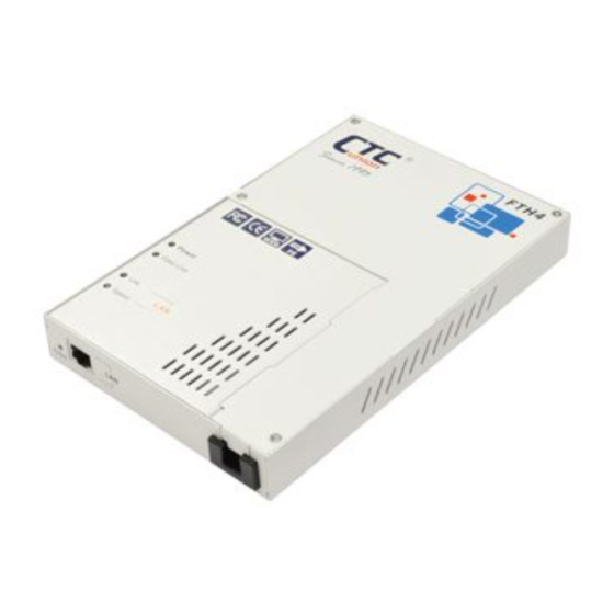
Thank you for choosing FTH4-1000MS & FTH4-100M Managed Gigabit & Fast Ethernet OAM/IP Media Converter with cable tray. Throughout this document, the two different models of this family will be referred to as FTH4-1000M & FTH4-100M (FTH4-1000MS will also be stated when necessary). -
Page 7: Product Features
Supports Auto Laser Shutdown (ALS) Function With built-in fiber cable tray FTH4-1000MS SFP socket supports a wide range of standard SFP modules to address any network situation. WARNING: Fiber optic equipment may emit laser or infrared light that can injure your eyes. Never look into an optical fiber or connector port. -
Page 8: Specifications
1.4 Specifications Model FTH4-1000M(S) FTH4-100M Item Optical Interface Duplex SC, ST, FC (FTH4-1000M) or SFP cage Connector Duplex SC, ST, FC (FTH4-1000MS) Data rate 100/1000Base-X 100Base-FX Duplex mode Full duplex on fiber Full duplex on fiber Electrical Interface Connector RJ-45, shielded... -
Page 9: Panel
1.6 Panel 1.6.1 Top & Front panel FTH4-1000M & FTH4-1000MS FTH4-100M Reset to default button LED indicators Cable holder RJ-45 port Figure 1. Top panel Figure 2. Front panel... -
Page 10: Wall Mounting Holes & Inside The Media Converter
1.6.2 Wall Mounting Holes & Inside the Media Converter Power DC jack Fiber optic port Cable tray management Wall mounting holes Figure 3. Wall mounting holes Figure 4. Inside the media converter... -
Page 11: Led Indicators
Flash when there is Ethernet traffic. LAN LINK There is no LAN port link. Light when the LAN speed is 100M. Green LAN Speed Amber Light when the LAN speed is 1000M. (for FTH4-1000MS only) If not lit, the LAN speed of 10M is indicated. -
Page 12: Reset To Default Button
1.8 Reset to Default Button The “Reset to Default” button is located next to RJ-45 UTP port. It is used to recover lost password or to return TCP/IP settings to factory default values. Use a pencil or blue-point pen and then press the button for 6 seconds then release to reset the device to the factory default settings. -
Page 13: Chapter 2 Installation
Chapter 2 Installation 2.1 Cable Tray Management FTH4-1000M & FTH4-100M have built-in cable tray that is used to organize excessive fiber in order. The installation of fiber cable in the cable tray is simple and straightforward. The following pictures describe the fiber installation step by step. Step 1. -
Page 14: Wall Mounting
2.2 Wall mounting FTH4-1000M & FTH4-100M can not only be placed on the flat desk but also be mounted on the wall. The media converter provides three wall mounting holes at the bottom panel that allows users to hang it vertically or horizontally depending on the actual wall mounting needs. The wall mounting installation methods are simple and straightforward. -
Page 15: Installation Of Sfp Modules (For Fth4-1000Ms Only)
2.3 Installation of SFP Modules (for FTH4-1000MS only) We supplied SFP modules are of the Bale Clasp type. The bale clasp pluggable module has a bale clasp that secures the module into the SFP cage and has a handle to aid in removing the module. -
Page 16: Chapter 3 Web Based Provisioning
Chapter 3 Web Based Provisioning 3.1 Introduction In an effort to make Networking devices easier to configure, many devices can now be configured via a Web Page, which should be familiar to all Internet users. The webpage is accessed by the Default IP Address of the device from a Web Browser such as Internet Explorer or Firefox in the following way: http://10.1.1.1/ (Assuming the device has Default IP Address of 10.1.1.1) Before accessing this device by web browser, the IP address must be known or it must be reset or changed to be used on the desired... -
Page 17: Web Main Page
3.3 Web Main Page When you successfully access the device, the first page you will see look like the one provided below. In this manual, we use Gigabit media converter’s (FTH4-1000M) Web configuration page as example. If you use Fast Ethernet media converter, some pages may vary. -
Page 18: System Information
3.4 System Information 3.4.1 Network Information The information displayed on this page gives specific device, network information, and port status for the local FTH4-1000MS and for any remote that is accessible via IEEE802.3ah OAM in-band management. -
Page 19: Dd Information
3.4.2 DD Information The DD or DDOM information is read from the MSA compliant SFP module and can be displayed via the web user interface. -
Page 20: Local Settings
3.5 Local Settings The following is a listing of the local settings that can be performed via the web interface for the Gigabit & Fast Ethernet media converter. We will go through the settings here, one by one, in detail. -
Page 21: Ip Configuration
3.5.1 IP Configuration Use this screen to set the TCP/IP configuration for the local unit. Note, that if you change the IP address you could lose remote management for this device. Remember to save settings under the “Tools” menu. The above shows the factory default TCP/IP settings for Gigabit & Fast Ethernet media converters. The “Description” field varies depending on the device you use. -
Page 22: Password Setting
3.5.2 Password Setting This function is used to modify the default password for the device. The password is required so that only authorized users have access to the management of the device. Key in the current password and type in the new password twice, then click the “Apply” button. After applying settings, do not forget to save the configuration under the ‘Tools’... -
Page 23: Converter Configuration
3.5.3 Converter Configuration The Converter configuration menu includes special features of Gigabit & Fast Ethernet media converter. All of these special functions will be explained on the following two pages. Select the proper radio buttons and then click the “Apply” button. Remember to save settings under the “Tools”... - Page 24 This converter is capable of supporting Jumbo Frames (9k byte packets) when this option is enabled. Note that in order to support jumbo frames, the TP speed and duplex must match the FX. Jumbo Frames are not typically used on a normal network, since most devices are not able to handle them and they would be truncated.
- Page 25 Management Packet High Priority is a function which is enabled by default. Unless VLAN is enabled, this function is meaningless. The packet priority is included as 3 bit priority in the VLAN tag. Management packets will be assigned the highest priority so that even in the presence of high traffic throughput, this converter can still be easily managed.
-
Page 26: Port Configuration
3.5.4 Port Configuration This screen is for the configuration of the electrical Ethernet port (TP) and the optical port (FX). Both the TP and FX Port Active are enabled by default. If a port is disabled, all transmission through this port will be stopped. The device’s LAN or Fiber Link LED will be extinguished if the port is made inactive. -
Page 27: Mib Counters
3.5.5 MIB Counters The counters have an accumulation of received bytes and packets for each port (UTP, Fiber and Management). The distribution of those packets is further delineated into packet types (Unicast, Multicast, Broadcast) and packet sizes. Also counted are illegal packets and dropped events. -
Page 28: Vlan
3.5.6 VLAN 3.5.6.1 VLAN Group... -
Page 29: Vlan Per Port Configuration
By default, this device is VLAN unaware, making it completely transparent to VLAN tags. In most application, this device only acts as a media converter and therefore the device should be transparent. This device does support up to 16 VLAN groups. By using the check boxes for each port, the ingress access to different VIDs can be controlled here for TP, FX and management. -
Page 30: Management Vlan Setting
3.5.7 Management VLAN Setting This function is independent of any other VLAN group or per port settings. The settings here provide a very quick method to configure how access to management is controlled. There are three control 'states' defined as follows: Disable: This means that the "access control"... -
Page 31: Remote Settings
3.6 Remote Settings When 802.3ah is active in both the local and remote unit (with fiber connection), the in-band management provides an embedded channel to control and configure the remote by using OAM (layer 2) Ethernet packets. The same settings available to the local unit are available under the Remote Setting menu, with the exception of password setting. -
Page 32: 802.3Ah Configuration
3.7.1 802.3ah Configuration To use the OAM functions, the 802.3ah Function setting must be enabled. It is not enabled by default. The 802.3ah mode is used to configure an OAM pair. In a pair, one unit must be ‘active’, while the other must be ‘passive’. We typically place the remote converter (CPE) in ‘passive’... - Page 33 * Error Frame Period (error frames per n frames): The number of frame errors within the last n frames has exceeded a threshold. * Error Frame Seconds Summary (error seconds per m seconds): The number of error seconds (1-second intervals with at least one frame error) within the last m seconds has exceeded a threshold.
-
Page 34: Loop Back Test
The unidirectional support indicates whether or not the device supports the transmission of OAMPDUs on links that operate in unidirectional mode. Use the radio button to enable Unidirection Support if it is capable of sending OAMPDUs when the receive path is non- operational. -
Page 35: 802.3Ah Status
3.7.3 802.3ah Status... - Page 36 The Global Config fields display the state of OAM, if OAM is enabled. We can also see the MAC addresses of the local and remote units in the OAM manageable pair. The Flags Field list the results of individual events based on the results of OAM protocol data units (OAMPDUs). Lastly, when two OAM devices start negotiation, there is Discovery Information passed between them.
- Page 37 One of the most critical problems in an access network for carriers is differentiating between a simple power failure at the customer premise and an equipment or facility failure. Dying gasp provides this information by having a station indicate to the network that it is having a power failure.
-
Page 38: Tools
3.8 Tools The Tools menu includes the System Reboot, Save and Restore settings and Firmware Upgrade functions. 3.8.1 System Reboot When the converter is rebooted, all counters and registers are cleared and the converter starts fresh. If OAM is enabled, the discovery process will start. -
Page 39: Save And Restore
3.8.2 Save and Restore After performing configuration of the converter, the settings must be saved. Click the “Save To Flash” button to save settings. If you wish to abandon all settings and return to the previous settings before doing configuration, click the “Load From Flash” button. To restore all settings to factory default, click the “Reset To Factory”... -
Page 40: Firmware Upgrade
3.8.3 Firmware Upgrade If functions are added or if factory default settings are changed, the firmware in the converter will require upgrading. The only method to do upgrade for this converter is through the local Web (HTTP) user interface. The firmware image is uploaded from the browser (Post), it is checked for integrity, the flash is erased and then the flash is written with the new image. -
Page 41: Logout
3.9 Logout Logging out will ensure that the management session with the device is terminated. This is especially important if you are using a public computer to manage the device. Once logged out, a password must be entered to access the device again. Click the “OK”... -
Page 42: Troubleshooting
3.10 Troubleshooting 3.10.1 Factory Default Apply power to the device and allow 25-30 seconds to fully boot. Using a pencil or ball-point pen, press the 'DEFAULT' recessed push- button switch (located on the face plate) and hold for 10 seconds or more then release. DO NOT POWER OFF; Allow the unit to again fully reboot (about 25 seconds). -
Page 43: Led Observations
3.10.3.3 Fiber Link Test Following a complete power and boot up (about 25 seconds) the converter will be active. For FTH4-1000MS, place a known good SFP module into Fiber Port cage. Use a simplex patch cable (single fiber strand, LC to LC), route the SFP Tx back to the Rx optical connection. -
Page 44: Operation Checks
3.10.4 Operation Checks 3.10.4.1 Converter Check A very easy way to ensure a pair of FTH4-1000M or FTH4-100M is passing traffic, is to place them between two PCs. Connect PC1 to LAN of one converter and PC2 to LAN of the other converter. When the two PCs can ping each other, it indicates FTH4-1000M or FTH4-100M pair is operational. -
Page 45: Web Access Test
3.10.4.3 Web Access Test With the device reset to factory default, connect a PC and configure the PC to the 10.1.1.0 network (10.1.1.100 recommended). Use a PC to connect to the device at its factory default IP address of 10.1.1.1 using a web browser (Internet Explorer, Firefox, Chrome, etc.). The local web page login page should display. - Page 46 This page is intentionally left blank.