Table of Contents
Advertisement
Service Booklet for the Engineer
for Gas Condensing Boilers
6 720 610 333-00.1R
ZSBR 7-28 ICS1
GC-Number: 41 108 04
ZWBR 8-30 ICC2
GC-Number: 41 108 09
ZBR 8-35 ICS1
GC-Number: 41 108 05
ZWBR 11-37 ICC1
GC-Number: 41 108 10
ZWBR 7-28 HE plus
GC-Number: 47 311 56
ZWBR 11-35 HE plus
GC-Number: 47 311 57
Advertisement
Table of Contents

Related Manuals for Worcester ZSBR 7-28 ICS1


Summary of Contents for Worcester ZSBR 7-28 ICS1
- Page 1 Service Booklet for the Engineer for Gas Condensing Boilers 6 720 610 333-00.1R ZSBR 7-28 ICS1 GC-Number: 41 108 04 ZWBR 8-30 ICC2 GC-Number: 41 108 09 ZBR 8-35 ICS1 GC-Number: 41 108 05 ZWBR 11-37 ICC1 GC-Number: 41 108 10...
-
Page 2: Table Of Contents
Contents Contents Safety precautions Symbols Layout of Appliance (ZSBR/ZWBR) Operation Standard display Displaying service functions Setting service functions Resetting service functions to factory settings 5 2.4.1 Resetting service functions 0.0 to 4.9 to their factory settings (Reset 1): 2.4.2 Resetting service functions 0.0 to 9.9 to the factory setting (Reset 2): Boiler service functions Summary... -
Page 3: Safety Precautions
Safety precautions Safety precautions Symbols Safety instructions in this document Repairs are identified by a warning-triangle sym- B Repairs may only be carried out by an approved bol and are printed on a grey back- installer! ground. B Before carrying out any work on the appliance, switch it off at the master switch! Signal words indicate the seriousness of the hazard in B Even when the appliance is switched off at the mas-... -
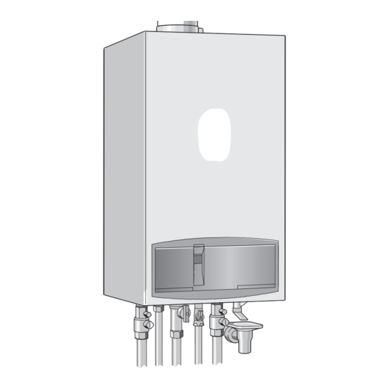
Page 4: Layout Of Appliance (Zsbr/Zwbr)
Layout of Appliance (ZSBR/ZWBR) Layout of Appliance (ZSBR/ZWBR) Testing points: flue gas Fan fixing screws Automatic vent Burner fixing screws Fan connector Electrode assembly: Flame sensing electrode Mixer unit Ignition electro- Silencer CH flow NTC CH flow sensor Gas supply pipe Flue gas safety CH flow safety... -
Page 5: Operation
Operation Operation B Press the Instructions on the use of the text display module are button. given in the operating and installation instructions for The cursor is pointing to Display service the boiler. parameters. B Press and hold the button (for about 5 sec- onds) until the display shows shows Adjust service parameters and the first service function to be set, e.g. -
Page 6: Boiler Service Functions
Boiler service functions Boiler service functions Summary Range adjustable Reset Text display message Display from - to Value Last fault 00 - FF Clear only Flow temp. sensor 0 - 99 °C Hot water temp. sensor 0 - 99 °C Stor. - Page 7 Boiler service functions Range adjustable Reset Text display message Display from - to Value Link 8 - 9 open closed Link Ls-Lr open closed Stor. tank. therm.. (7-9) blocked heat demand Room therm. LSM blocked heat demand LSM release blocked heat demand Timer ch.
- Page 8 Boiler service functions Range adjustable Reset Text display message Display from - to Value Cycle time (hot water) 0 - 60 min 0 min Duration (hot water) 0 - 30 min 1 min Pump map (heating) 0 Pump step adjustable 4 Prop.
-
Page 9: Explanation Of Service Functions
Boiler service functions Explanation of service functions • Min mode: the appliance runs constantly at minimum output. 0.0 Last fault The text display shows MIn mode. The 2-digit dis- play alternates between the CH flow temperature The last fault can also be recalled for servicing pur- poses when the appliance is functioning correctly. - Page 10 Boiler service functions 2.7 Autom. anti-cycle mode 3.5 Pump blocking time (ZBR.. models only) If an outside-temperature controlled programmer is con- nected to the appliance, the anti-cycle time is adjusted Only applies if service function 3.4, Pump automatically. mode, is set to Pump mode 1 (external 3- Automatic adjustment of the anti-cycle time can be dis- way valve for heat store charging is con- abled.
- Page 11 Boiler service functions Shows the status of channel 2 of the timer integrated in The heating output can be limited to any level between the text display module or the separate programmer. the min. rated heat output and the max. rated heat out- If that channel’s status is “Heat demand”, hot water put to suit the specific heat requirements.
- Page 12 Boiler service functions If a stratified-charge tank is connected, it is useful to 7.2 Antiblock. map pump (not ZBR...) have the function activated. The appliance is supplied with this function activated. The delayed cut-in of the pump then prevents cold If the pump threatens to jam, an oscillating pump action water being pumped through the tank and cooling it is activated.
- Page 13 Boiler service functions 8.5 Siphon fill program The trap filling programme ensures that the condensa- tion trap is filled when the appliance is first installed or after it has been shut down for a long period: The con- densation trap prevents flue gas escaping from the appliance into the room in which it is installed.
-
Page 14: Rectifying Faults
Rectifying faults Rectifying faults Boiler failure codes indication Summary 4.1.1 ... on the boiler 4.2.1 Appliance faults In order to identify the specific boiler failure a two digit alphanumeric code is used. This allows a quick fault identification and solution. The text display shows the message Fault EA. - Page 15 Rectifying faults Appliance faults Loose or broken contact on heat store NTC sensor Specified CH flow tempera- ture from TA... programmer exceeded Table 3 Programmer faults Set room temperature not reached Set room temperature exceeded by large amount Set room temperature not reached Temperature rises instead of falling...
-
Page 16: How To Use The Fault Tables
Rectifying faults How to use the fault tables The procedure is explained using the fault code If the fault is now cured, the appliance will revert to nor- EA as an example: mal operation and the fault-finding process is complete. Now simply re-check the setting of the two temperature The table heading shows the fault code and a general controls. -
Page 17: Faults Indicated On Display
Rectifying faults Faults indicated on display flashing. Controlled-characteristic pump has run dry Check Action B Power OFF the appliance. System pressure below 1.2 bar? yes: B Check appliance and system for water leaks and repair as necessary. B Top up system. B Turn ON the appliance. - Page 18 Rectifying faults flashing. Heat store NTC sensor 2 defective Check Action B Activate menu option B Is the connector for heat store NTC sensor 2 cor- yes: Show service parameters. roded , damaged or dirty? Replace affected components. B Select .4 Stor.tank temp.sensor2 .
- Page 19 Rectifying faults flashing. Hot water NTC sensor defective Check Action B Activate menu option B Is the connector for hot water NTC sensor corro- yes: Show service parameters. , damaged or dirty? Replace affected com- ponents. B Select .2 Hot water temp.sensor . ↓2.
- Page 20 Rectifying faults flashing. No correct electrical connection Check Action B Turn switch until it clicks into position. Mode selector switch is between two settings A8? ↓2. B Power OFF the appliance. B Turn ON the appliance. yes: Wiring between TR 2 and text- ↓3.
- Page 21 Rectifying faults flashing. Heat store NTC sensor 1 not detected Check Action ↓2. Is lead for heat store NTC sensor yes: correctly routed, i.e. not through B Route connecting lead for heat store tempera- cable clamp? ture sensor as specified in installation instruc- tions.
- Page 22 Rectifying faults flashing. Code plug not detected. Check Action B Power OFF the appliance. No fault or fault code FC displayed yes: on text display? B Fit code plug (correctly), making sure code number (see Appendix) is correct. B Turn ON the appliance. b1? ↓2.
- Page 23 Rectifying faults flashing. Fan speed too low Check Action ↓2. Fan lead connector properly con- yes: nected? B Power OFF the appliance. B Plug in connector. B Turn ON the appliance. C6? ↓2. Fan lead defective? yes: B Power OFF the appliance. B Replace fan lead.
- Page 24 Rectifying faults flashing. Wrong signal from pin 8-9. Check Action ↓2. Jumper 8 - 9 fitted correctly? yes: B Power OFF the appliance. B Fit jumper 8 - 9 correctly, tighten screw. B Turn ON the appliance. d3? ↓2. ↓3. B Turn ON the appliance.
- Page 25 Rectifying faults flashing. The heating outlet NTC sensor is damaged. Check Action B Activate menu option yes: The heating outlet NTC sensor is in short circuit: Show service parameters. B Power OFF the appliance. B Select .1 Flow temp.sensor. B Replace CH flow NTC sensor; observe fitting Is a temperature between 0.
- Page 26 Rectifying faults flashing. Safety temperature limiter has tripped. Check Action B Top up system. Is the heating pressure between 1 yes: and 2 bar? B Vent appliance. B Press , does appliance restart??? E9?↓2. ↓2. Is the pump blocked? yes: B Unblock the pump.
- Page 27 Rectifying faults flashing. Safety temperature limiter has tripped. Check Action B Power OFF the appliance. B Change the fuse. yes: B Remove fuse SI 3 from appliance B Turn ON the appliance. PCB control board and test for B Press , does appliance restart??? continuity.
- Page 28 Rectifying faults flashing. During operation: flame not detected Check Action ↓6. Is the flame present? yes: ↓2. ↓3. Is the gas cock open? yes: B Open the gas cock B Press , does appliance restart??? EA? ↓3. B Vent supply pipe. Is there air in the supply pipe? yes: B Press...
- Page 29 Rectifying faults flashing. During operation: flame not detected Check Action ↓7. Is the ground connection correct? yes: B Rewire correctly as specified in the installation instructions. B Press , does appliance restart??? EA? ↓7. ↓8. Two phase net: yes: Is there a resistor fitted between Pe B Power OFF the appliance.
- Page 30 Rectifying faults flashing. During operation: flame not detected Check Action B Adjust to correct level. Is flue gas CO level incorrect yes: B Press , does appliance restart??? EA? ↓12. ↓12. ↓13. B Activate menu option Show serv- yes: ice parameters. ↓16.
- Page 31 Rectifying faults flashing. During operation: flame not detected Check Action B Replace electrode assembly. Electrode assembly defective? yes: B Power OFF the appliance. B Turn ON the appliance. B Remove electrode assembly. B Press , does appliance restart??? Electrodes worn out? EA? ↓18.
- Page 32 Rectifying faults (and possibly ) flashing. Internal failure Check Action B Activate menu option B Record figure displayed in service report. Show service parameters. ↓2. B Select 9.3 GFA-Asic-error. A message is displayed. B Select 5.2 GFA status / error. B Record figure displayed in service report.
- Page 33 Rectifying faults flashing. Although appliance switches off, flame still detected Check Action B Power OFF the appliance. Electrode(s) dirty or defective. B Replace electrode assembly. B Turn ON the appliance. B Press , does appliance restart??? F7? ↓2. B Power OFF the appliance. B Dry PCB control board (e.g.
- Page 34 Rectifying faults flashing. After appliance switches off flame is detected Check Action B Clean condensation trap discharge pipe. Is condensation trap in condensing yes: boiler blocked? B Press , does appliance restart??? FA? ↓2. ↓2. Electrodes faulty. B Replace electrode assembly. B Turn ON the appliance.
- Page 35 Rectifying faults flashing. Text display module not detected Check Action B Power OFF the appliance. No fault or fault code FC displayed on text display? B Fit code plug (correctly), making sure code number is correct (see Appendix). B Turn ON the appliance. FC? ↓2.
-
Page 36: Faults That Are Not Displayed
Rectifying faults Faults that are not displayed 4.5.1 Appliance faults Boiler indicates P1, P2, P3 at start-up and then restarts with P1.. Check Action B Turn ON the appliance. Fuse T 1.6 A (312) defective. yes: B Change the fuse. B Power OFF the appliance. - Page 37 Rectifying faults Flue gas levels incorrect, CO level too high Check Action ↓2. Does the gas supply type match the yes: specifications on the appliance iden- B Convert appliance to correct gas type tification plate? ↓3. B Test gas supply pressure , - OK? yes: B Decommission appliance.
- Page 38 Rectifying faults Ignition too harsh, ignition poor Check Action ↓6. B Activate menu option yes: Show service parameters. ↓2. B Select 5.1 Permanent ignition. Continuous ignition OK? ↓3. Ignition lead connected to ignition yes: electrodes? B Connect cable to ignition electrode. B Press button Ignition poor? ↓3.
- Page 39 Rectifying faults Ignition too harsh, ignition poor Check Action ↓8. B Test gas supply pressure - OK?. yes: B Decommission appliance. B Notify gas company. B Check flue and repair or replace if necessary. Problem with flue? yes: B Check CO level in combustion Ignition poor? ↓8.
- Page 40 Rectifying faults Specified CH flow temperature from TA... programmer exceeded Check Action If outside-temperature controlled programmer (TA...) is connected to boiler: • The anti-cycle time is adjusted by the programmer to the suit the system. • The factory setting for the anti-cycle time (3 min.) and the heating mode hysteresis setting, if applicable, are deactivated.
-
Page 41: Programmer Faults
Rectifying faults 4.5.2 Programmer faults Set room temperature not reached (TR 2) Check Action B Turn up thermostatic valve(s). Thermostatic valve(s) set too low? yes: ↓2. ↓2. CH flow temperature control on yes: B Turn up CH flow temperature control. boiler set too low? ↓3. - Page 42 Rectifying faults Set room temperature not reached Check Action Thermostatic valve(s) set too low? yes: B Turn up thermostatic valve(s). ↓2. ↓2. B Correct heating characteristic. Heating characteristic set too low? yes: ↓3. ↓3. B Turn up CH flow temperature control. CH flow temperature control on yes: boiler set too low?
- Page 43 Rectifying faults Set room temperature exceeded by large amount Check Action Do radiators get too hot? yes: TR 2: B Decrease setting of “Heating” control ↓2. ↓2. B Select better installation location Bad choice of location for program- yes: mer, e.g. outside wall, near window, ↓3.
- Page 44 Rectifying faults Heat store fails to heat up Check Action with TR 2: B Increase CH flow temperature control setting. CH flow temperature control on boiler set too low. B Increase hot water temperature control setting. Hot water temperature control on boiler set too low 7 181 465 347 (01.07)
-
Page 45: Appendix
Appendix Appendix NTC values 5.1.2 CH flow NTC sensor, heat store NTC sen- sor, constant hot water NTC sensor and 5.1.1 Outside temperature sensor hot water NTC sensor Outside temperature Temperature ( °C) ( °C) Measurement Resistance tolerance ± 10% ( Ω) Measurement Resistance... -
Page 46: Electronic Schemes
Appendix Electronic schemes o - orange bl - black r - red p - purple 25 V 230 V 230V/AC 1 2 4 7 8 9 328.1 mains supply 52.1 6 720 610 603 - 03.1O Fig. 2 Ignition transformer Temperature limiter, heat exchanger Code plug Flue gas temperature limiter... -
Page 47: List Of Most Important Replacement Parts
Appendix List of most important replacement parts Component Order no. Remarks Component Order no. Remarks Switchbox Heat exchanger PCB control 8 748 300 385 board Temperature lim- 8 729 000 144 110 °C iter STB Transformer 8 747 201 358 Flue gas temper- 8 729 000 144 Ignition lead... -
Page 48: Approved Corrosion Inhibitors And Anti-Freeze Fluids For Central Heating Water
Appendix Approved corrosion inhibitors and anti-freeze fluids for central heating water Mixing concentra– tion % by Manufacturer Description Remarks weight With all anti-freeze fluids and corrosion inhibitors, it is extremely important to observe the manufacturer’s recom- mended concentration levels and to check the concentration regularly. In the case of anti-freeze fluids, it should be noted that the efficiency of fluid-to-fluid heat transfer diminishes as the anti-freeze concentration increases. -
Page 49: Detecting Corrosion By Cfcs
Appendix Detecting corrosion by CFCs Halogenated hydrocarbons in the combustion air cause surface corrosion of the affected metal components. The combustion chamber and the boiler heating sur- faces (including stainless steel) are particularly suscep- tible to this type of attack as are the metal components in the flue socket, flue joints and the chimney. - Page 50 Appendix 7 181 465 347 (01.07)
- Page 51 Appendix 7 181 465 347 (01.07)
- Page 52 Appendix...
Need help?
Do you have a question about the ZSBR 7-28 ICS1 and is the answer not in the manual?
Questions and answers