Table of Contents
Advertisement
Quick Links
Advertisement
Table of Contents

Subscribe to Our Youtube Channel
Related Manuals for Worcester ZWBR 7-28 HE plus


Summary of Contents for Worcester ZWBR 7-28 HE plus
-
Page 1: Installation And Servicing Instructions
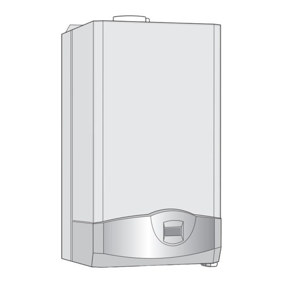
Installation and Servicing Instructions GREENSTAR HE plus combi Wall mounted condensing boiler for central heating and mains fed domestic hot water 6 720 610 598-00.1O ZWBR 7-28 HE plus GC-Number: 47 311 56 ZWBR 11-35 HE plus GC-Number: 47 311 57... -
Page 2: Table Of Contents
Contents Contents Settings Safety precautions 6.8.1 Heating (TR 2) 6.8.2 Hot Water Symbols (Storage Tank, ZSBR models only) 6.8.3 Service Details of the appliance Individual timer programmes EC Declaration of Conformity Standard package Individual settings Description of appliance Mechanical settings Accessories 7.1.1 Checking the size of the expansion vessel Casing dimensions... -
Page 3: Safety Precautions
Safety precautions Safety precautions Symbols Safety instructions in this document If you smell gas are identified by a warning-triangle sym- y Turn off gas service cock at the meter. bol and are printed on a grey back- y Open windows and doors. ground. -
Page 4: Details Of The Appliance
Details of the appliance Details of the appliance EC Declaration of Conformity Description of appliance This appliance is in accordance with the applicable • Wall-mounted appliance, siting not dependent on requirements of the Gas Appliance Directive, Boiler Effi- room size ciency Directive, Electromagnetic Compatibility Direc- •... -
Page 5: Accessories
Details of the appliance Accessories • Standard horizontal flue kit at 100 mm outside diameter for flues upto 4 m in length. • Flue duct kits for horizontal (125 mm outside diameter) for flue lengths upto 10 m (ZWBR 11-35) or 13 m (ZWBR 7-28) and vertical flue systems for flue lengths 12 m (ZWBR 11-35) or 15m (ZWBR 7- 28). -
Page 6: Layout Of Appliance
Details of the appliance Layout of appliance 221.1 221.2 234.1 32.1 6 720 610 597 - 02.1O Fig. 2 Heatronic control Fixing points Heat exchanger safety temperature limiter 221.1 Flue duct Hot water NTC sensor 221.2 Combustion air intake Testing point for gas supply pressure Fan assembly Pressure gauge Appliance type sticker... -
Page 7: Function
Details of the appliance Function 234.1 ϑ 29.1 52.1 ϑ 6 720 610 597- 03.1O Fig. 3 Bosch Heatronic control Adjustable gas flow restrictor Temperature limiter, heat exchanger Adjusting screw for min. gas flow volume Hot water NTC sensor Control valve Testing point for gas supply pressure Motor Pressure gauge... -
Page 8: Electrical Wiring Diagram
Details of the appliance Electrical wiring diagram o - orange g - green bl - black r - red p - purple 25 V 230 V 230V/AC 1 2 4 7 8 9 328.1 mains supply 52.1 6 720 610 602 - 02.1O Fig. -
Page 9: Technical Data
Details of the appliance Technical data ZWBR 7-28 ZWBR 11-28 ZWBR 11-35 ZWBR 14-35 Units Natural gas Propane Natural gas Propane Max. rated heat output net 40/30 °C central heating 30.1 30.1 37.5 37.5 Max. rated heat output net 50/30 °C central heating 29.8 29.8 37.1... - Page 10 Details of the appliance Condensate analysis, mg/l VERTICAL 125 mm FLUE SYSTEM Ammonium 1.2 Nickel 0.15 Lead ≤ 0.01 Mercury ≤ 0.0001 Overall Diametter of Duct Cadmium ≤ 0.001 Sulphate 1 Flue Terminal / Duct 1360 Chromium ≤ 0.005 Zinc ≤ 0.015 Assembly Tin ≤...
-
Page 11: Installation Regulations
Installation regulations Installation regulations Installation Gas Safety (Installation & Use) Regulations 1998: All y Always turn off the gas cock before car- gas appliances must be installed by a competent per- rying out any work on components son. Failure to install correctly could lead to prosecu- which carry gas. -
Page 12: Domestic Hot Water
Installation Domestic hot water Sealed systems Any regulations specified by the local water company The appliance must not be operated without the system must be observed. being full of water, properly vented and pressurised. The final 600 mm of the mains cold water connection to The expansion vessel has a volume of 10 litres (ZWBR the applaince should be made in copper tube only. -
Page 13: Siting The Appliance
Installation APPLIANCE Refer to Fig.1 Appliance water flow diagram A drain cock should be fitted at the lowest point of the heating circuit and the appliance WRC approved filling loop Lockshield valve Central heating return Domestic Central heating flow hot water Radiator valve Domestic... -
Page 14: Wall Mounting Frame Assembly
Installation Wall mounting frame assembly y Take the wall mounting frame out of the package and y Screw the pre-plumbing manifold with two screws to screw together with 6 screws as shown in fig. 7. Use the wall mounting frame. the outer lugs on the top and bottom horizontal sec- tions for the appliances that are 512 mm wide. -
Page 15: Fitting The Appliance
Installation Condensate drain Fitting the appliance Prepare the condensate discharge system. Refer to fig. 11. The condensate drainage pipe should be a Benchmark: For optimum performance standard drain pipe material , i . e. PVC, PVC-U, ABS after installation, this boiler and its asso- etc. -
Page 16: Checking The Connections
Fit flue duct connector onto appliance flue spigot. The only flue systems that may be used are those sup- plied by Worcester Heat Systems. y Secure with the two screws supplied. The flue system must be installed in accordance with the requirements of BS5440:1. -
Page 17: Siting The Flue Terminal
Installation 3.9.1 Siting the Flue Terminal The flue must be installed in accordance with lighting, activated by passive infra-red sensing heads. BS 5440:1 and the Building Regulations. Flue terminals If the terminal is less than 2 m above a surface to which in carports and under balconies are to be avoided. -
Page 18: Installation Of The Flue
Installation 3.9.2 Installation of the flue The standard 100 mm diameter horizontal flue system is suitable for lengths upto 4 m. Flues upto 650 mm do not require an extension duct assembly. Flues between 1600 mm and 4000 mm require exten- sion duct assemblies. - Page 19 Installation Terminal Assembly Flue Turret Maximum 1600mm Outer Wall Clamp Extension Clamp Duct 6 720 610 602 - 09.1O Fig. 17 Flue with one extension Terminal Assembly Flue Turret Outer Wall Clamp Clamp Extension Extension Clamp Duct Duct 6 720 610 602 - 10.1O Fig.
-
Page 20: Flue Duct Preparation And Assembly
Installation 3.9.3 Flue duct preparation and assembly Measure the flue length L. Refer to fig. 20, 21. Outer Wall Flue Terminal Face Raised Ring locating the terminal relative to the outside wall face NOTE: THE FLUE MUST BE INCLINED T O THE 6 720 610 576 - 20.1O BOILER 6 720 610 602 - 12.1O... -
Page 21: Electrical Connections
Electrical connections Electrical connections Connecting the appliance y Always disconnect the power supply to the appliance at the mains before carry- To gain access to the mains connection remove the ing out any work on the electrical sys- drop down facia cover. The drop down cover is tems and components. -
Page 22: Connecting Tr2 Room Thermostat
Electrical connections y Cut cable grommet to diameter of cable. Mains Voltage external controls connections NOTE: Only double insulated controls not requiring an earth can be used Ns Ls L Ns Ls L Remove Link Motor 230 V R oom Thermostat Connections 230 V Pr ogrammer Connections Ns Ls L 230 V r oom thermos t at and... -
Page 23: Commissioning
Commissioning Commissioning 317 366 367 6 720 610 597 - 05.1O Fig. 29 Commissioning Pressure gauge Safety valve Automatic vent Never run the appliance when empty or Reset button unpressurised. Master switch Temperature control for central heating Service cocks on CH flow and return Benchmark Water Treatment: For optimum perform- Hot water Gas cock (shown in off position) -
Page 24: Switching The Appliance On/Off
Commissioning y Unscrew the condensation trap (358) and pull out, fill y Always disconnect the appliance from with approx. 1/4 l of water and refit. Refer to fig. 29. the power supply (fuse, circuit breaker) y Adjust charge pressure of expansion vessel to static before carrying out any work on the head of the central heating system (see page 32). -
Page 25: Setting The Domestic Hot Water Temperature And Flow Rate
Commissioning Setting the domestic hot water y To increase the flow rate (max. 14 l/min): turn screw on flow switch anti-clockwise (+). temperature and flow rate The outlet temperature will decrease relative to the 5.5.1 Domestic hot water temperature increase in the flow rate. The hot water temperature can be set to between y To reduce the flow rate (min. -
Page 26: Fault Condition
Commissioning Fault Condition A list of faults that may occur is given on page 46. In the unlikely event of a fault occuring while the appli- ance is in operation: The display and the text display then show a fault code and the button may also flash. -
Page 27: Text Display
Text Display Text Display General Description y To start programming, press any button, e. g. The display lighting switches on and the main menu • The text display is used to display information about is displayed: the appliance and the system and to alter the settings displayed. -
Page 28: Deleting A Setting
Text Display y Use the button to set the day of the Menu structure week. Submenu y Press the button to confirm the setting. The cursor then returns to the top line. Main Parameters to -or- menu change/select - Hours y Press the button to confirm the setting and hour/day... -
Page 29: Setting The Time/Day
Text Display Setting the time/day Setting options • Maximum of six switching points per day with three 6.4.1 Setting the time and day different operating modes (Heating, Economy, Frost For details of how to set the time and day, refer to protection). -
Page 30: Setting The Economy Temperature
Text Display 6.5.2 Setting the Economy temperature i Info This option allows you to set the room temperature for y Select Info from the main menu. Economy mode ( Off (Economy) ). You can view the following information: This function is only active if: •... -
Page 31: Settings
Text Display Settings y Press the button. The display shows Change value. 6.8.1 Heating (TR 2) y Press to set the number of seconds in 24 hours. Optimum Start Basic setting: “+ 0 s” y From the main menu, select Settings and from the first submenu, select Heating. -
Page 32: Individual Settings
Individual settings Individual settings Mechanical settings y Rotate yellow button through 180° and replace (dot facing inwards). 7.1.1 Checking the size of the expansion vessel The CH flow temperature is no longer limited. Maximum pressure at maximum CH flow temperature is Control setting CH flow temperature 2.5 bar. -
Page 33: Setting The Anti-Cycle Time (Service Function 2.4)
Individual settings y Press the button to exit the menu. 7.2.3 Setting the maximum CH flow tempera- ture (Service Function 2.5) Setting service functions The maximum CH flow temperature can be set to Only the service functions that can be set are displayed. between 35 °C and 88 °C (factory setting). -
Page 34: Converting The Appliance To Different Gas Types
Converting the appliance to different gas types Converting the appliance to different gas types The setting is factory sealed at maximum. Adjustment to Setting the gas/air ratio the rated heat input and min. heat input is not neces- y Switch off the appliance at the master switch (O). sary. -
Page 35: Testing Combustion Air/Flue Gas At Set Heat Output
Converting the appliance to different gas types adjustable gas flow restrictor (63) until the CO level ZWBR 7-28 reading – below 100 ppm at ZWBR 7-28 at max. reading – below 200 ppm at ZWBR 11-35. rated heat at min. rated y Re-adjust the CO level if necessary. -
Page 36: Testing Co And Co
Maintenance y Insert testing probe about 80 mm into the testing Maintenance point and seal testing point. y Always disconnect the appliance from the electrical power supply (fuse, circuit breaker) before carrying out any work on the electrical systems or components. y Always turn off the gas cock before car- rying out any work on components which carry gas. -
Page 37: Pre-Service Check List
Maintenance Pre-Service Check List Date Call up the last fault stored by the text- display , (see page 31). Check ionisation current, Service Function 3.3, (see page 38). Perform visual check of air/flue duct. Check gas supply pressure mbar (see page 34). Test combustion air/flue gas (see page 35). -
Page 38: Description Of Servicing Operations
Maintenance Description of servicing operations Primary Heat exchanger There is a special accessory kit (no. 840) for cleaning The combustion performance must be checked before the heat exchanger, order no. 7 719 001 996. and after any servicing work on the combustion and burner components. - Page 39 Maintenance y Loosen any deposits in the heat exchanger from top Burner to bottom using the cleaning blade. Refer to fig. 46. y Check that the gas cock is turned off and the master switch is in the OFF position. y Remove the clips (1) and unscrew the two bolts (2).
- Page 40 Maintenance Condensation trap Expansion vessel In order to prevent spillage of condensate the conden- The expansion vessel should be checked once a year. sation trap should be completely removed, (see y Depressurise appliance. page 38, fig. 45). y If necessary, adjust expansion vessel charge pres- y Unscrew condensation trap and check connection to sure to static head of the heating system.
-
Page 41: Replacement Of Parts
Maintenance Replacement of Parts y Remove the pcb control board. Before changing any components check that the gas is turned off and that the appliance is electrically isolated. When necessary close the system valves and drain the appliance. Refitting is a reverse of the procedure for removal using new seals or o-rings as appropriate. -
Page 42: Fan Assembly
Maintenance 9.3.2 Fan Assembly 9.3.3 Pump y Switch off the appliance. y Disconnect the appliance from the power supply. y Remove two switchbox fixing screws (1.). Refer to fig. 55. y Lower switchbox (2.). y Remove screw from underside of right-hand plastic cover plate (3.). -
Page 43: 3-Way Diverter Valve
Maintenance 9.3.4 3-way diverter valve 9.3.6 Sensors y Switch off the appliance. y Check that the appliance is electrically isolated. y Disconnect appliance from the power supply. Central Heating Flow Temperature Sensor – y Turn off service cocks. Item 36, fig. 2, 52 y Unplug connector from 3-way valve motor. -
Page 44: Gas Valve
Maintenance 9.3.7 Gas Valve 9.3.8 Domestic Hot Water Heat Exchanger y Check that the gas cock is turned off. y Refer to section 9.2. y Lower the control panel. Refer to fig. 55. y Use new seals when fitting the new heat exchanger. y Pull off the solenoid connections at the rear of the 9.3.9 Electrode assembly... -
Page 45: 14Flow Switch
Maintenance 9.3.14 Flow switch y Pull forward from the top and lift the heat exchanger from the casing. y Shut the mains water inlet valve and drain the domes- y Transfer components, as necessary, to the new heat tic hot water circuit. exchanger. -
Page 46: Appendix
Appendix Appendix 10.1 Fault Codes More detailed fault finding procedures are described in the Service Booklet for the Engineer number 7 181 465 347. Display code Description Remedy pump has run dry Check system pressure, add water and bleed system as necessary Hot water NTC sensor defective. -
Page 47: Short Parts List
Appendix 10.2 Short parts list Description Qty GC Spare part number Sensor - Flue gas temp. 8 729 000 144 0 Sensor - CH flow temp. 8 714 500 087 0 Sensor - DHW flow temp. 8 714 500 054 0 Control board 8 748 300 418 0 Gas valve ZWBR 7-28... -
Page 48: Zwbr 7-28 N
Appendix 10.3 Heating/hot water output settings ZWBR 7-28 N.G. Natural gas G20 Display Heat output, Heat input, Gas vol. flow rate (l/min at t = 80/60 °C) code 15.0 11.3 11.4 20.0 14.1 14.3 24.9 16.9 17.1 29.9 19.8 20.0 34.9 22.6 22.8... -
Page 49: Zwbr 11-35 N
Appendix 10.5 Heating/hot water output settings ZWBR 11-35 N.G. Natural gas G20 Display Heat output, Heat input, Gas vol. flow rate (l/min at t = 80/60 °C) code 10.5 10.7 18.6 14.1 14.2 24.9 17.6 17.8 31.1 21.1 21.3 37.3 24.6 24.9 43.5... -
Page 50: Operational Flow Diagrams
** NOTE: The appliance controls can be set to one of Pump ON Fan to Ignition Diverter valve start speed. spark Ignition sequence 2 modes of operation. operates. Gas valve opens. 5 secs 1. “Comfort“ mode - Full pre-heat Burner shut-down if 2. -
Page 51: 2Central Heating Function
Over temperature Burner remains OFF Gas valve shuts. shut-down if water until flow temperature Pump remains ON. temperature is 5°C is below set value. above set value. Room thermostat and/or mains Boiler programmer or operates to link ON Pump ON Burner Fan speed Boiler... - Page 52 Appendix Appendix EXCELLENCE COMES AS STANDARD Worcester Heat Systems Limited, Cotswold Way, Warndon, Worcester WR4 9SW. Telephone: (01905) 754624 Fax: (01905) 754619...
Need help?
Do you have a question about the ZWBR 7-28 HE plus and is the answer not in the manual?
Questions and answers