Table of Contents
Advertisement
Quick Links
Advertisement
Table of Contents
Troubleshooting

Related Manuals for WarmFlow WS18


Summary of Contents for WarmFlow WS18
- Page 1 Boiler Manual Wood Pellet Boiler WS18/WP18 For use with ENplus A1 wood pellets only. Look for the ENplus A1 symbol. Incorporating: User Instructions Installation Instructions Service Record Guarantee Terms & Conditions Registration Documents LEAVE THIS MANUAL WITH THE END USER...
- Page 2 Servicing must be conducted by a Warmflow engineer or other trained and competent engineer. A service history must be maintained in Section 8 of this manual.
-
Page 3: Table Of Contents
CONTENTS KEY INFORMATION ......................1 The Clean Air Act 1993 and Smoke Control Areas ..............4 USER INSTRUCTIONS ......................5 Filling the Pellet Hopper ......................5 System Pressure ........................6 System Filling ..........................6 User Control Interface ........................ 7 2.4.1 Home Screen Icons and their meaning. - Page 4 APPLIANCE INSTALLATION/COMMISSIONING CERTIFICATE & REGISTRATION..69 APPLIANCE SERVICE RECORDS..................72 APPENDIX A – SUPPLEMENTARY INSTALLATION AND OPERATING INSTRUCTIONS FOR THE UK MARKET ......................83 APPENDIX B – CUSTOMER CONNECTION WIRING SCHEMATIC ......91...
-
Page 5: Key Information
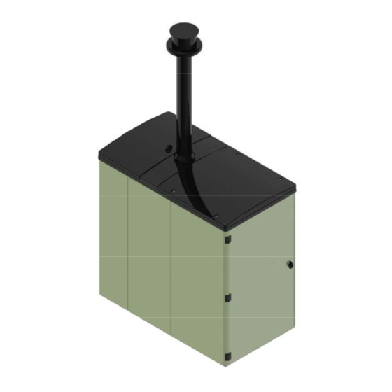
Extension pieces, bends and bracketry can be purchased from Warmflow stockists. The appliance is also fitted with a flue draught stabiliser. The wood pellet fuel is loaded into the integrated hopper located at the rear of the appliance (see Figure 1 above). - Page 6 Figure 2 - Service Access. (Service Lid and Insulation Removed) Once removed the service lid gives access to the heat exchanger for servicing and routine maintenance as shown in Figure 2. To clean the internal surfaces of the heat exchanger, remove the main HE inspection door and the HE cleaning mechanism door.
- Page 7 Vacuuming with a dedicated ash vacuum cleaner is recommended. Failure to clean the combustion pot as directed may restrict the flow of air within the appliance adversely affecting its performance. Description Model WS18/WP18 Type Wood Pellet Boiler Dimensions (mm) Width...
-
Page 8: The Clean Air Act 1993 And Smoke Control Areas
1.1 The Clean Air Act 1993 and Smoke Control Areas Both appliances, the WS18 and WP18 comply with the requirements of the Clean Air Act 1993 and are suitable for installation in smoke control areas. The appliances meet the emissions limits for particulate matter and NO as stated by DEFRA. -
Page 9: User Instructions
The wood pellets used to fuel the appliance must be compliant with the ENPlus A1 pellet standard. Using alternative pellets will invalidate the product warranty. It should be also noted that the Warmflow wood pellet boiler appliance is suitable for use in smoke control areas when burning ENPlus A1 pellets only. -
Page 10: System Pressure
The minimum pressure, as indicated by the black needle, must not be less than 0.5 bar when the appliance is cold and typically around 2.5 bar when the appliance is at normal operating temperature. If the pressure is outside this range contact Warmflow or your installer. -
Page 11: User Control Interface
2.4 User Control Interface The appliance’s user control interface (see Figure 5) has been designed to maximise the ease of use and efficiency of the heating system. All user interactions with the appliance are via the display panel. Hence the display panel should be mounted at an easily accessible location. -
Page 12: Home Screen Icons And Their Meaning
2.4.1 Home Screen Icons and their meaning. The home screen appears as shown in Figure 6. Fuel Status Current Page Boiler Status Cleaning Status Figure 6: Icon Descriptions. Boiler Status Icon Status Meaning Boiler OK The appliance is functioning normally. There are no faults or alerts. Servicing is not due. The appliance has reached alert condition but will continue to operate as normal. -
Page 13: Using The Main Menu
2.4.2 Using the Main Menu The main menu can be accessed by pressing once on the ‘Program key’. This displays the main menu as shown in the Figures 7 and 8 below. Figure 7: Main Menu Page 1. Figure 8: Main Menu Page 2. ‘Down Arrow’... - Page 14 Alarms: Selecting the alarms menu enters the alarms display. This can also be entered at any time by pressing the ‘Display active alarms’ key. The screen shown in Figure 10 will be displayed when no alarms are present. Figure 10: Alarms Screen. When an alarm is present, the ‘Display active alarms’...
- Page 15 Settings: Selecting the settings menu enters a sub-menu which has a number of information and setting screens. These can be viewed and adjusted by the user. The information and setting screens are displayed in the same format as the main menu screen and may be accessed in the same way.
- Page 16 Information: Selecting the information sub-menu allows 3 information screens to be viewed. The first two information screens display a list of values relating to the operational performance of the appliance as shown in Figures 15 and 16. These values are for monitoring purposes only and cannot be altered.
- Page 17 Figure 16: Information Screen (2 of 3). Text Description Expected Value(s) Valve Pos. Indicates the position of the anti- 50% in Standby Mode. condensation valve in the appliance. Modulates between 0 - 100% in all other modes. 0% = Valve fully opened = all heat to property 100% = Valve closed = water circulation in the heat exchanger (HE) only to raise the HE temperature and avoid condensation.
- Page 18 Information screen 3 displays a list of values relating to the software used in the appliance as shown in Figure 17. The most important of these values is the Software Ver. (meaning software version). The example in Figure 17 displays the Software Ver. as 3.106b. It is beneficial to be aware of the software version used on the appliance prior to seeking technical support.
- Page 19 The appliance has a start-up sequence as shown in Figure 18 (see page 16) and will only begin firing if there is a heat demand present, i.e. a signal from a time clock or programmer, or if Freeze Risk Mode is enabled (See table 6). As the appliance is fully modulating the control system will monitor the heat demand and work to meet the demand as efficiently as possible.
- Page 20 Figure 18: Flow Chart.
- Page 21 The “OK” status beside the time display on information screen 1 can change (see Figure 15). Further explanation of what can be displayed in this area on information screen 1 is provided in Table 6. Status Description The appliance can operate as normal providing there are no active alarms. Power Failure Recovery - There has been an electrical power failure (power cut) and power has now been restored.
- Page 22 Tests, In/Out. Help: Selecting the help menu, as shown in Figure 20 below, displays the contact details for Warmflow who should be contacted if you require further assistance or if you encounter a problem with your appliance. Figure 20: Help Screen.
-
Page 23: Cleaning
2.5 Cleaning 2.5.1 Cleaning Scheduler The control system built into the appliance includes a cleaning scheduler that continually records the operating hours of the appliance. When a pre-defined number of operating hours has elapsed, an alert is triggered to indicate that a scheduled clean is due. The ‘Display Active Alarms’... -
Page 24: Cleaning Status
2.5.2 Cleaning Status The cleaning status of the appliance can be viewed at any time. From the home screen (Figure 22), press the ‘Program key’ to view the main menu. Figure 22: Home Screen Scroll to “3. Cleaning” in the Main Menu using the ‘Down Arrow’... - Page 25 If the cleaning status screen in Figure 25 is displayed, sufficient operating hours have elapsed for the cleaning scheduler to trigger a cleaning alert and a scheduled clean is due. This status will be displayed for three days with a daily count down indicating the remaining time by which cleaning should be completed.
- Page 26 Once cleaning is initiated, if the cleaning procedure is interrupted for any reason, the screen in Figure 28 will be displayed when the cleaning menu option is selected. Press the ‘Enter’ key to resume and complete the cleaning procedure. Figure 28: Resume Cleaning Screen NOTE –...
-
Page 27: Cleaning Procedure
There are 16 steps to cleaning a WS18/WP18 Wood Pellet Boiler Appliance. Please complete all steps with care in order to prolong the life of the appliance. If an alert screen is displayed (Figure 21), press the ‘escape’... - Page 28 STEP 2 – Activate the Cleaning Preparation Utility • From the cleaning status screen, press the ‘Enter key’ to activate the cleaning preparation utility. • A progress bar will appear on screen as the appliance prepares itself for cleaning (See Figure 31).
- Page 29 STEP 4 – Open the Front Casing Door (PHOTOS) • Ensure that access to the front of the appliance is unobstructed and safe to work in. Ensure that the green coloured front casing door can be fully opened. • Unlock the front casing door of the appliance using the key provided as shown in Figure Figure 33: Opening the Front Casing Door.
- Page 30 Door Release Light Button Green Isolator Light Switch Figure 34: User Switches and Lights • Press and HOLD the large, green-coloured door release button located beside the isolator switch, highlighted in Figure 34. The combustion door interlock can be heard to release when this button is pressed.
- Page 31 • Lift the combustion door handle up while still holding the door release button as shown in Figure 35 “Lift UP”. • The combustion door can now be opened and the door release button can be released. Leave the combustion door handle fully up until STEP 14. •...
- Page 32 • Lift the combustion pot vertically upwards away from the cleaning knives (See Figure 38). • Set the combustion pot to the side ensuring that if hot, it is not placed in contact with materials that may be affected by heat. Heat Exchanger Combustion...
- Page 33 STEP 9 – Clean the Combustion Pot • Empty any loose material from the combustion pot into the ash pan as shown in Figure Figure 39: Emptying the Combustion Pot • Use a suitable brush* to dislodge any build-up of combustion deposits from the inside of the combustion pot as shown in Figure 40.
- Page 34 • Dislodge any hard deposits from the surface of the combustion pot as shown in Figure 41 Figure 41: Dislodging Hard Deposits from the Combustion Pot • Empty any dislodged material from the combustion pot into the ash pan for a second time (See Figure 39).
- Page 35 STEP 10 – Clean the Heat Exchanger • Use a suitable brush* to remove any build-up of ash/dust from the combustion pot area of the heat exchanger. (* A dedicated ash vacuum cleaner may also be used as shown in Figure 43.
- Page 36 • Check that the seal on the bottom of the combustion pot is in place and in good condition (Refer to Figure 45). If this seal is removed or has become worn or damaged it should be replaced by a Warmflow engineer or other trained and competent engineer. This seal is critical for efficient operation of the appliance.
- Page 37 STEP 14 – Close the Combustion Door • Ensure the combustion door handle is in the fully up position as shown in Figure 46. Press and hold the green coloured door release button if necessary (see Figure 34) in order to raise the handle. Figure 46: Combustion Door Handle Up •...
- Page 38 STEP 15 – Close the Front Casing Door • Close the front casing door and rotate the door handle clockwise through 180⁰ to engage the latch. • Lock the front casing door of the appliance using the key provided. STEP 16 – Confirm Cleaning is Complete •...
- Page 39 Figure 50: Main Menu - Cleaning o The cleaning status screen should now be displayed with the prompt “Resume clean?” as shown in Figure 51. Figure 51: Cleaning Resume Screen. o Press the ‘Enter key’ to display the appliance ready for cleaning screen in Figure 52.
-
Page 40: Installation Requirements
3 INSTALLATION REQUIREMENTS The installation must comply with regional Building Regulations. The maximum noise level generated by the appliance is well within the residential noise limitations and is similar to that of a high efficiency oil boiler. The appliance is secured on a wooden pallet for shipping. The appliance is fixed to this pallet using four screw fasteners through its base. -
Page 41: Service Access
3.1.2 Service Access Clearance should be provided above and in front of the appliance to allow for routine servicing. The rear of the appliance casing and any one side panel may be positioned beside a wall or boundary. At least 600mm is required at the front and accessible side of the appliance, although maximising access is recommended. -
Page 42: Drain Cock
3.2 Sealed Systems 3.2.1 Expansion Vessel (WS 18 Models only) The WS18 appliance is supplied with an 18 litre expansion vessel charged to 1.0 bar. This can accommodate a maximum combined appliance and system volume of 160 litres. If these maximum total system volumes are to be exceeded, additional expansion capacity will be required. -
Page 43: System Filling
3.2.2 System Filling For the WS18 appliance a filling point complete with a filling loop is supplied fitted to the expansion vessel. The filling loop must be disconnected from the mains supply after filling. A system pressure when cold of 1 bar is recommended. - Page 44 The drainage hose must not be affected by any blockage which could lead to condensation backfilling into the heat exchanger of the appliance causing corrosion. Figure 55: Condensate Trap Plumbing.
- Page 45 Plumbing layout Casing knockouts (20mm and 45mm) can be found on both sides and rear of the appliance along with cut-outs in the galvanised base which allow for the pipes to exit the casing below ground level, see Figure 56 and 57 below. It is advised that the pipe work from the appliance to the interior of the property must be 28mm and this must be adequately insulated.
-
Page 46: Wiring Layout
3.3 Wiring Layout All wiring must be carried out in accordance with current IEE wiring regulations. It is recommended the user interface controller is mounted in an easily accessible location within the property. The wiring connection to the user interface is via a pLAN connection and must be wired from the wiring panel to the user interface controller with the supplied CAT5e cable. - Page 47 Fuses 3x ceramic cartridge fuses are provided to protect circuits within the appliance. The fuses must only be replaced by a Warmflow Engineer, or another trained and competent Engineer after determining the reason for failure. Fuses are located adjacent to the mains supply wiring connections, and protect the following...
-
Page 48: Flue System
3.4 Flue System The appliance comes with an 80/100mm twin wall flue comprising a 500mm long flue section and a 500mm long flue terminal. The supplied flue system is adequate only if the flue terminal is more than 2.3 meters from an adjacent wall or surface as required by building regulations. - Page 49 To assemble the supplied flue refer to Figure 62: 1. Insert the 500mm long flue section complete with weatherproof cover into the flue spigot on top of the appliance. 2. Secure the flue with supplied self-drilling screws through the punched tabs. 3.
-
Page 50: Commissioning And Servicing
4.1 Commissioning – Approximate time to complete: 2 hours Note: It is the responsibility of the installer to ensure that the appliance is properly commissioned by Warmflow, or other trained and competent Engineer. Failure to do so WILL invalidate ALL warranties. - Page 51 These parameters may be assigned by accessing the ‘1. Parameters’ utility within the Engineer menu. The Commissioning menu contains additional functions that should not be required during normal machine installation checks – see WS18/WP18 technical manual for further information. • From the home screen (Figure 64), press the ‘Program key’...
- Page 52 • Insert the engineer password into the engineer password screen (Figure 66) using the ‘Up Arrow’ key and ‘Down Arrow’ key, and then the ‘Enter key’ to advance to the next character: Press the ‘Enter key’ to confirm. Figure 66: Engineer Password Screen. •...
- Page 53 When the appliance is used on an open vented system, set parameter to N.C. Mode 1 This setpoint refers to low heat demand installations – please refer to the WS18 / WP18 technical manual for further details. Auger Mode Variable This is the current auger mode that has been set following the performance of (Factory Set).
- Page 54 STEP 5 – Initial Firing of the Appliance Before firing, ensure that the combustion pot and ash pan are in place as they may have been displaced during transport/installation (refer to Figure 3). Switch the appliance on, ensuring all controls are calling for heat. Under normal conditions the appliance will follow the startup procedure as shown in Figure 18.
- Page 55 • From the home screen (Figure 70), press the ‘Program key’ to view the main menu. Figure 70: Home Screen • Scroll to “5. Engineer” in the Main Menu using the ‘Down Arrow’ and confirm selection using the ‘Enter key’. (Figure 71) Figure 71: Main Menu - Engineer •...
- Page 56 • Scroll using the ‘Down Arrow’ to ‘Preset Drop test’ as shown in Figure 74. This will indicate a ‘Run No’ condition. This means the test is not currently running: Figure 74: Preset Drop Test Screen “Run No” • Push and hold the green combustion door interlock release button. The combustion door interlock will be heard to release.
- Page 57 The CO level is controlled by the combustion fan and is self-correcting and should not require alteration at commissioning. However, if the CO level is continually outside the range of 6% to 14% please contact Warmflow.
- Page 58 (See Section 7 of this manual) returned to Warmflow within 30 days from the date of installation and 90 days from the date code stamped on the appliance. A copy of this certificated should remain with the appliance/householder.
-
Page 59: Servicing
The appliance must be serviced at least annually or as indicated by the user interface controller by a Warmflow Engineer or other competent Engineer. This is necessary in order to optimise performance of the appliance and to ensure its efficiency and safety for the user. -
Page 60: Alarms And Troubleshooting
Suggested actions for each alarm condition are also included. The suggested actions are attributed to the user (typically the homeowner) or a Warmflow engineer or other trained and competent engineer, and should be conducted in the order suggested. The possible causes and suggested actions are not exhaustive. - Page 61 2.5.3 has not been completed fully/correctly The appliance has not been serviced within Service the appliance. Servicing must be the time period indicated in the service conducted by a Warmflow engineer or other alerts. competent engineer who has received appropriate training.
- Page 62 Alarm Screen Possible Cause(s) Suggested Action(s) Action By User Engineer The wood pellets loaded into the Follow the instructions on the screen: combustion pot are poor quality, damp or Wait for the counter on the screen to reach • contaminated. 0 seconds.
- Page 63 Alarm Screen Possible Cause(s) Suggested Action(s) Action By User Engineer Air is trapped in the heating system Remove all trapped air from the heating system creating steam inside the top of the heat paying particular attention to the appliance exchanger. Common with new installations. itself.
- Page 64 Alarm Screen Possible Cause(s) Suggested Action(s) Action By User Engineer The clear 6mm ID hose connected to the Ensure the clear 6mm ID hose is not damaged pressure sensor and combustion door is and is connected to the correct port on the disconnected or damaged.
- Page 65 The temperature of the appliance has This alarm must be assessed further by a exceeded a high limit value. Warmflow engineer or other trained and competent engineer. The temperature in the drop chute has Let the appliance cool down. Test the operation...
- Page 66 Alarm Screen Possible Cause(s) Suggested Action(s) Action By User Engineer The grate cleaning motor is faulty. Test the operation of the grate cleaning motor, mechanism and switch and repair/replace if The grate cleaning mechanism is faulty. necessary. The switch on the grate cleaning mechanism is faulty.
-
Page 67: Troubleshooting
5.2 Troubleshooting Other faults or problems with the appliance that may not trigger an alarm are listed in “Table 15 – Troubleshooting guide” below Symptom Possible Cause(s) Suggested Action(s) Action By User Engineer No heat supplied to property. Time clock switched off, or room Check timeclock to determine if the heating thermostat set too low. - Page 68 Auger motor is turning, no pellets are being Auger drive mechanism fault. Check auger drive coupling at top of auger. delivered to combustion pot. Alarm ‘Probe B01 fault or disconnected’. Airlock in boiler causing high temperature. Bleed heating system to remove airlocks. Airlocks keep occurring in heating system.
-
Page 69: Your Guarantees, Terms & Conditions
In the event that components are not capable of repair, Warmflow will provide replacement parts for any such components. Warmflow reserves the right to repair or replace components within the period of guarantee at a time and location that is most convenient to the company. - Page 70 In addition: • The commissioning certificate in respect of your Boiler must be returned to Warmflow within thirty (30) days from the date of installation. Please note if your Boiler has not been installed within three (3) months of the date of dispatch from Warmflow, then this guarantee will be deemed to have commenced upon such date of dispatch.
- Page 71 Warmflow will have no responsibility or liability for repairs or works performed by a person who has not been authorised by Warmflow. Warmflow will accept no liability for the cost of repairs resulting from incorrect installation, inadequate commissioning, lack of annual servicing, misuse, tampering or repair by persons who have not been authorised by Warmflow.
- Page 72 (l) Defects caused by the improper use or storage of the boiler and in particular (but without limitation) Warmflow shall not be liable in the case of defects arising from normal deterioration or improper or faulty handling or processing of the boiler by the customer;...
-
Page 73: Appliance Installation/Commissioning Certificate & Registration
• Carbon copies of the certificate are produced automatically. Register the Appliance. • • Remove the white copy of the Installation/Commissioning Certificate. • Send the certificate to Warmflow By post using the envelope provided to: Warmflow Engineering Co. Ltd. Lissue Industrial Estate... - Page 74 Calibration Date: Appl i ance Seri al No.: Date Code: Fuel Brand: ENplus 1: MCS Approva l No.: WS18: BSI KM 608787/2 WS18: BSI KM 608787/2 Concentration Boiler Parameters (See Section 4 of the product manual). 3.Householder & Installation Address Details.
- Page 75 INTENTIONALLY LEFT BLANK...
-
Page 76: Appliance Service Records
• All product warranties will be invalidated if the appliance is not serviced at least annually or as indicated by the user interface controller by a Warmflow engineer or other trained and competent Engineer and details recorded in the service record section of this... -
Page 77: Service Record
PLEASE COMPLETE USING BLOCK CAPITALS. Service Record 1. Date of Servicing: 1. Service Engineer Details. MCS/SEAI Registration No. Service Company Name: Service Company Address: Contact Telephone No.: (LandLine) (Mobile) Service Engineer’s Name: Service Engineer's's E-Mail: 2. Appliance Servicing Checklist. Combus ti on Pot & Sea l i ng Rope Pel l et Hopper As h Pa n &... - Page 78 PLEASE COMPLETE USING BLOCK CAPITALS. Service Record 2. Date of Servicing: 1. Service Engineer Details. MCS/SEAI Registration No. Service Company Name: Service Company Address: Contact Telephone No.: (LandLine) (Mobile) Service Engineer’s Name: Service Engineer's's E-Mail: 2. Appliance Servicing Checklist. Combus ti on Pot & Sea l i ng Rope Pel l et Hopper As h Pa n &...
- Page 79 PLEASE COMPLETE USING BLOCK CAPITALS. Service Record 3. Date of Servicing: 1. Service Engineer Details. MCS/SEAI Registration No. Service Company Name: Service Company Address: Contact Telephone No.: (LandLine) (Mobile) Service Engineer’s Name: Service Engineer's's E-Mail: 2. Appliance Servicing Checklist. Combus ti on Pot & Sea l i ng Rope Pel l et Hopper As h Pa n &...
- Page 80 PLEASE COMPLETE USING BLOCK CAPITALS. Service Record 4. Date of Servicing: 1. Service Engineer Details. MCS/SEAI Registration No. Service Company Name: Service Company Address: (LandLine) (Mobile) Contact Telephone No.: Service Engineer’s Name: Service Engineer's's E-Mail: 2. Appliance Servicing Checklist. Combus ti on Pot & Sea l i ng Rope Pel l et Hopper As h Pa n &...
- Page 81 PLEASE COMPLETE USING BLOCK CAPITALS. Service Record 5. Date of Servicing: 1. Service Engineer Details. MCS/SEAI Registration No. Service Company Name: Service Company Address: Contact Telephone No.: (LandLine) (Mobile) Service Engineer’s Name: Service Engineer's's E-Mail: 2. Appliance Servicing Checklist. Combus ti on Pot & Sea l i ng Rope Pel l et Hopper As h Pa n &...
- Page 82 PLEASE COMPLETE USING BLOCK CAPITALS. Service Record 6. Date of Servicing: 1. Service Engineer Details. MCS/SEAI Registration No. Service Company Name: Service Company Address: Contact Telephone No.: (LandLine) (Mobile) Service Engineer’s Name: Service Engineer's's E-Mail: 2. Appliance Servicing Checklist. Combus ti on Pot & Sea l i ng Rope Pel l et Hopper As h Pa n &...
- Page 83 PLEASE COMPLETE USING BLOCK CAPITALS. Service Record 7. Date of Servicing: 1. Service Engineer Details. MCS/SEAI Registration No. Service Company Name: Service Company Address: (LandLine) (Mobile) Contact Telephone No.: Service Engineer’s Name: Service Engineer's's E-Mail: 2. Appliance Servicing Checklist. Combus ti on Pot & Sea l i ng Rope Pel l et Hopper As h Pa n &...
- Page 84 PLEASE COMPLETE USING BLOCK CAPITALS. Service Record 8. Date of Servicing: 1. Service Engineer Details. MCS/SEAI Registration No. Service Company Name: Service Company Address: Contact Telephone No.: (LandLine) (Mobile) Service Engineer’s Name: Service Engineer's's E-Mail: 2. Appliance Servicing Checklist. Combus ti on Pot & Sea l i ng Rope Pel l et Hopper As h Pa n &...
- Page 85 PLEASE COMPLETE USING BLOCK CAPITALS. Service Record 9. Date of Servicing: 1. Service Engineer Details. MCS/SEAI Registration No. Service Company Name: Service Company Address: Contact Telephone No.: (LandLine) (Mobile) Service Engineer’s Name: Service Engineer's's E-Mail: 2. Appliance Servicing Checklist. Combus ti on Pot & Sea l i ng Rope Pel l et Hopper As h Pa n &...
- Page 86 PLEASE COMPLETE USING BLOCK CAPITALS. Service Record 10. Date of Servicing: 1. Service Engineer Details. MCS/SEAI Registration No. Service Company Name: Service Company Address: Contact Telephone No.: (LandLine) (Mobile) Service Engineer’s Name: Service Engineer's's E-Mail: 2. Appliance Servicing Checklist. Combus ti on Pot & Sea l i ng Rope Pel l et Hopper As h Pa n &...
-
Page 87: Appendix A - Supplementary Installation And Operating Instructions For The Uk Market
9 APPENDIX A – SUPPLEMENTARY INSTALLATION AND OPERATING INSTRUCTIONS FOR THE UK MARKET... - Page 88 USER MANUAL FOR INDEPENDENT PELLET or CHIP FIRED BOILERS SUPPLEMENTARY INSTALLATION INSTRUCTIONS FOR THE UK MARKET TO BE READ IN CONJUNCTION WITH THOSE IN THE INSTRUCTION BOOKLET These instructions together with those in the instruction booklet cover the basic principles to ensure the satisfactory installation of the boiler, although detail may need slight modification to suit particular local site conditions.
- Page 89 Metal Parts When installing or servicing this boiler care should be taken to avoid the possibility of personal injury. BOILER PERFORMANCE Refer to the main instruction manual for details of the boiler’s performance. PREPARATORY WORK AND SAFETY CHECKS IMPORTANT WARNING This boiler must not be installed into a chimney that serves any other heating appliance.
- Page 90 If there is no existing chimney then any new system must be to the designation described above and in accordance with Building Regulations Approved Document J. A single wall metal fluepipe is suitable for connecting the boiler to the chimney but is not suitable for use as the complete chimney.
- Page 91 Connection to chimney All the boilers have a flue gas connector that allows connection to either a masonry chimney or a prefabricated factory made insulated metal chimney in accordance with the instructions. This connection should never be reduced in diameter to lower than that of the flue gas connector of the boiler.
- Page 92 USER MANUAL FOR INDEPENDENT PELLET or CHIP FIRED BOILERS SUPPLEMENTARY OPERATING INSTRUCTIONS FOR THE UK MARKET TO BE READ IN CONJUNCTION WITH THOSE IN THE INSTRUCTION BOOKLET WARNING NOTE Properly installed, operated and maintained this stove will not emit fumes into the dwelling. Occasional fumes from de-ashing and re-fuelling may occur.
- Page 93 Boiler Access Access to the boiler should be restricted for children, aged and/or infirm persons by way of a lockable door to the room in which the boiler is installed. Chimney cleaning The chimney should be swept at least twice a year. It is important that the flue connection and chimney are swept prior to lighting up after a prolonged shutdown period.
- Page 94 Permanent air vent The boiler requires a permanent and adequate air supply in order for it to operate safely and efficiently. In accordance with current Building Regulations the installer may have fitted a permanent air supply vent into the room in which the boiler is installed to provide combustion air. This air vent should not under any circumstances be shut off or sealed.
-
Page 95: Appendix B - Customer Connection Wiring Schematic
10 APPENDIX B – CUSTOMER CONNECTION WIRING SCHEMATIC... - Page 97 CODE 4220 Manual is accurate at the date of printing (E&OE) but will be superseded and ISSUE 4 should be disregarded if specifications and/or appearances are changed in the FEB 2015 interests of continued product improvement...
Need help?
Do you have a question about the WS18 and is the answer not in the manual?
Questions and answers