Advertisement
Table of Contents
Advertisement
Table of Contents

Related Manuals for minkaAire Aviation


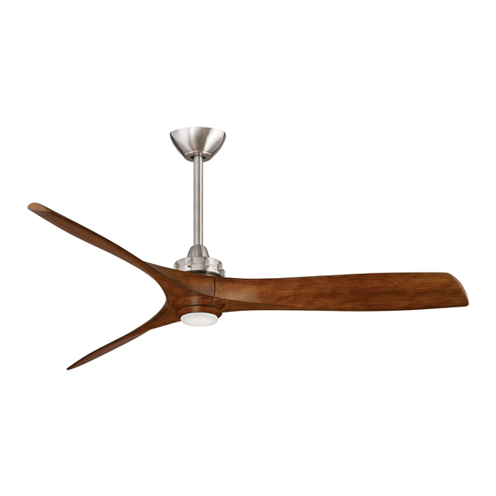
Summary of Contents for minkaAire Aviation
- Page 1 U.S. Patent(s) Pending...
- Page 2 This product is protected by United States Federal and/or State Law, including Patent, Trademark and/or Copyright laws. Manual design and all elements of manual design are protected by U.S. Fede ral and/or State Law, including Patent, Trademark and/or Copyright Laws.
- Page 3 warranty is for one (1) year from the date of purchase from an authorized Minka-Aire dealer. This warranty is only valid to the original purchaser or user against all defects in material and workmanship (light bulbs excluded) for one (1) full year. Additionally, Minka-Aire warrants the motor only for the lifetime of the Minka Aire ceiling fan (excluding wall controls and electrical components), to the original purchaser or user.
- Page 4 Warranty Service Information To obtain warranty servic during the warranty period, the purchaser should return the fan with the sales receipt to the original place of purchase. The authorized Minka-Aire dealer, at its sole discretion, will either repair or replace the fan after verifying the legitimacy of the warranty ®...
-
Page 5: Table Of Contents
CONTENTS SAFETY FIRST ATTACHING THE FAN BLADES PACKAGE CONTENTS ATTACHING THE BOTTOM CAP AND RING BEGIN INSTALLATION OPERATING THE REMOTE CONTROL/WALL CONTROL HANGING THE FAN MAINTENANCE ELECTRICAL CONNECTIONS TROUBLESHOOTING FINISHING THE INSTALLATION SPECIFICATIONS 1151W. Bradford Court, Corona CA 92882 For Customer Assistance Call: 1-800-307-3267... -
Page 6: Safety First
SAFETY FIRST 1. Before you begin installing the fan, shut power off at the circuit breaker of the fuse box. 2. Be cautious! Read all instructions and safety information before installing your new fan. Review accompanying assembly diagrams. 3. Make sure that all electrical connections comply with local codes, ordinances, or National Electrical Codes. Hire a qualified electrician or consult a do-it-yourself wiring handbook if you are unfamiliar with installing electrical wiring. - Page 7 NOTE:The important safeguards and instructions appearing in this manual are not meant to cover all possible conditions and situations that may occur. It must be understood that common sense, caution and care are factors which can not be built into this product. These factors must be supplied by the person (s) installing, caring for and operating the unit.
-
Page 8: Package Contents
PACKAGE CONTENTS 1. Fan motor/housing 11. Remote control 5/32"(Ø4.4x9.4x0.5-1.0mm ass'y -10 tooth) wash(2 pcs) A. Blade attachment hardware: 2. Canopy C. #8-32x7mm texture hex #10-24x12mm hex screw Fan blade (7pcs) screws (7pcs) 4. Coupling cover D. M3 L hex wrentch(1pcs) B. -
Page 9: Begin Installation
BEGIN INSTALLATION Tools Required: Phillips screw driver; slotted screw driver;pliers;wire cutters; electrical tape. MOUNTING OPTIONS CEILING JOIST PARALLEL WOOD BRACE (MIN. 2" THICK) If there isn' t an existing mounting box,then read the following instructions.Shut the CROSS BRACE OUTLET power off at the circuit breaker or fuse box. NOTE: THIS CEILING FAN EXCEEDS THE MAXIMUM WEIGHT SPECIFIED BY UL FOR OUTLET BOX HANGING FROM A STANDARD OUTLET BOX. -
Page 10: Hanging The Fan
HANGING THE FAN WARNING: All of the parts, hardware and components such as the Step 5: Now lift motor assembly into position and place downrod ball hanger bracket and hanger ball have been provided for your safety into hanger bracket. Rotate until the check groove has dropped into the and the proper installation of your new ceiling fan. - Page 11 Downrod Coupler Cover Outlet Box Hanger Ball Canopy Coupler Hanger Bracket Hanger Bracket Hitch Pin Set Screw Canopy cap Hitch Pin Washer Clevis Pin Registration Slot Lock Washer Coupling Cover Downrod Washer Blade Holder Downrod Fig.5 Fig.6 Fig.8 Fig.9 Clevis Pin Screw Fig.7...
-
Page 12: Electrical Connections
ELECTRICAL CONNECTIONS WARNING:To avoid possible electrical shock be sure electricity is turned off at the main fuse or breaker box before wiring. Note: The Aire Control System is equipped with a learning frequency function which has 256 code combination to prevent potential interference from other remote units. The frequency on your Receiver and Transmitter units have been preset at the factory. - Page 13 Step 2. If your outlet box has a GROUND wire (Green or Bare Copper) connect this wire to the Hanger Ball and Hanger Bracket Ground wires. If your outlet box does not have a Ground Wire, then connect Black(hot) Green or bare copper (ground) the Hanger Ball and Hanger Bracket Ground Wires together.
-
Page 14: Finishing The Installation
FINISHING THE INSTALLATION Step 1. Remove 1 of the 2 screws from the bottom of the hanger bracket and loosen the other one half a turn from the screw head. (Fig. 12) Step 2. Slide the canopy up towards the hanger bracket and place the key hole on the canopy over the screw on the hanger bracket, turn canopy until it locks in place at the narrow section of the key holes. -
Page 15: Attaching The Fan Blades
ATTACHING THE FAN BLADES Attach the fan blade to the blade holder on motor using the hex wrench provided in the screw pack. (Fig. 15) Receiver And Box Hex Wrentch Screw Blade Blade Holder Fig.15... -
Page 16: Attaching The Bottom Cap And Ring
ATTACHING THE BOTTOM CAP AND RING Align the holes on the bottom cap and the holes on the ring to the holes on the blades and using the hex wrench and hex screws provided secure both to the fan blades. (Fig.16) Blade Bottom Cap Ring... - Page 17 cold NOTE: THIS FAN HAS BEEN PRECISION BALANCED AT THE FACTORY AND WILL NOT NEED TO BE BALANCED AGAIN.
- Page 18 The DC motor has a built in safety against obstruction during operation, if the within 3 Minutes of turning the fans fan motor senses a obstruction it will get locked AC power on. and will not rotate until the power has been disconnected for 10 seconds.
- Page 19 Speed settings for warm or cold weather depend on factors such as room size, ceiling height and number of fans. NOTE: To change the direction of the rotation of the blades the fan must be in operation mode. Warm Weather (forward) A DOWNWARD airflow creates a cooling effect as shown in Figure 17.
-
Page 20: Care Of Your Fan
CARE OF YOUR FAN Here are some suggestions to help you maintain your fan. additional protection and enhanced beauty. Cover small scratches with a light application of shoe polish. 1. Because of the fan's matural movement,some connections may become loose. Check the support connections,brackets, and blade attachments 5. -
Page 21: Troubleshooting
TROUBLESHOOTING SYMPTOM SYMPTOM SYMPTOM Fan sound noisy Fan Wobble Fan will not start SOLUTION SOLUTION SOLUTION 1.Check to make sure the wall switch is turned on. 1. Allow a 24-hour "break in" period. Most 1.NOTE: All blade sets are grouped by noises associated with a new fan will go weight. - Page 22 SYMPTOM Frequency interference SOLUTION 1.Turn the power off to your ceiling fan. 2.Please use a small size tool to change the frequency setting on the control system. 3.Return power to the unit Note: After the AC power is on,do not press any other button on the transmitter before pressing the “Stop”...
-
Page 23: Specifications
SPECIFICATIONS Blade Span Fan Speed Volts Watts RPM's N.W. G.W. C.F. 0.07 3.17 2276 60" 0.10 4.98 3148 2.76" 0.15 8.07 4062 0.22 12.54 4957 0.30 17.50 5899 For any additional information about your 0.42 25.92 6604 Minka-Aire Ceiling Fan,please write to: ®... - Page 24 English Verison...
Need help?
Do you have a question about the Aviation and is the answer not in the manual?
Questions and answers