Table of Contents
Advertisement
Quick Links
Advertisement
Table of Contents

Related Manuals for Yamaha A-S2100


Summary of Contents for Yamaha A-S2100
-
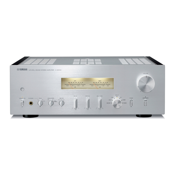
Page 1: Integrated Amplifier
Integrated Amplifier OWNER’S MANUAL... - Page 2 The technician performs exhaustive listening tests and every component is considered, in order to finally achieve the ideal sound. Yamaha’s tradition of audio quality stretches back over 125 years, and continues to live on in all Yamaha products today.
- Page 3 NS-10M Studio Monitor Speaker Became of the most popular studio monitors in the world. A-1 Integrated Amplifier PX-2 Turntable Yamaha’s first straight arm turntable. B-6 Power Amplifier B-2x Pyramid-shaped power amplifier. GT-2000/L Turntable First CD Player (CD-1) introduced in 1983...
- Page 4 ◆ Full floating and balanced circuit design achieves the full potential of analogue amplification An entirely new floating and balanced power amplifier achieves complete symmetry and permits full balanced transmission (amplification) from the input jack to just before the speaker jack. ◆...
-
Page 5: Controls And Functions
Controls and functions In this chapter, you will learn the controls and functions of A-S2100. - Page 6 CONTROLS AND FUNCTIONS Controls and functions ■ Front panel (pages 6 to 9) INPUT BASS TREBLE BALANCE LINE 1 STANDBY/ON PHONES TRIM SPEAKERS METER PEAK TUNER LINE 2 BI-WIRING MAIN DIRECT PHONO – – Off: Shows that the power of the unit is OFF. In this 1 STANDBY/ON, OFF switch condition, you can turn the power on only by Turns on or off this unit.
- Page 7 6 METER selector Switches the display of the meter to OFF, PEAK or OFF: Turns off the meter and the illumination. PEAK: Switches the meter to a peak level meter. The peak level meter shows a momentarily highest VOLUME audio output level. VU: Switches the meter to a VU (Volume Unit) level meter.
- Page 8 Controls and functions ■ Front panel (pages 6 to 9) INPUT BASS TREBLE BALANCE LINE 1 STANDBY/ON PHONES TRIM SPEAKERS METER PEAK TUNER LINE 2 BI-WIRING MAIN DIRECT PHONO – – BAL: Selects the component connected to the BAL A Remote control sensor jacks (balanced XLR jacks).
- Page 9 VOLUME PHONO AUDIO MUTE C PHONO switch E AUDIO MUTE indicator Selects the type of cartridge of the turntable connected Lights when the mute function is turned on with the to the PHONO jacks on the rear panel. AUDIO MUTE switch. MM: Choose this setting if the connected turntable F VOLUME control uses an moving magnet (MM) cartridge.
-
Page 10: Rear Panel
Controls and functions ■ Rear panel INPUT NORMAL (EIA) ATTENUATOR PHASE BYPASS ATT. NORMAL INV. + HOT (-6dB) - COLD SPEAKERS R CH LINE2 PRE OUT TUNER LINE 1 MAIN IN PHONO A OR B:4 MIN. /SPEAKER A+B:8 MIN. /SPEAKER 5 PHONO input jacks See page 16 for connection information. - Page 11 TRIGGER REMOTE AUTO POWER STANDBY SYSTEM CONNECTOR SPEAKERS L CH AC IN A OR B:4 MIN. /SPEAKER A+B:8 MIN. /SPEAKER A AUTO POWER STANDBY switch F Foot ON: The unit enters STANDBY mode automatically The feet of this unit include built-in spikes. Using the if not operated for 8 hours.
-
Page 12: Remote Control
TUNER: Selects the tuner connected to the TUNER jacks SOURCE LAYER 4 Yamaha tuner control buttons Control functions of Yamaha tuner. Refer to the owner’s manual of your tuner for details. Note VOLUME Some Yamaha tuners cannot be controlled by this remote control. MUTE... - Page 13 5 p CD key 8 VOLUME +/– keys Turns the Yamaha CD player ON or switches it to Control the volume level. STANDBY mode. Note OPEN/CLOSE key The VOLUME keys do not affect when you select MAIN Opens/closes the disc tray of the Yamaha CD player.
-
Page 14: Installing Batteries In The Remote Control
Controls and functions ■ Installing batteries in the remote control ■ Operating range of the remote control Remove the battery compartment cover. Insert the two batteries (AAA, R03, UM-4) according to the polarity markings (+ and –) on the inside of the battery compartment. Approximately 6 m (20 ft) The remote control transmits a directional infrared beam. -
Page 15: Connections
Connections In this section, you will make connections between A-S2100, speakers, and source components. - Page 16 Connections CD player or network CD player with Speakers A player with XLR jacks RCA jacks (R channel) Tuner INPUT ATTENUATOR PHASE BYPASS ATT. NORMAL INV. (-6dB) SPEAKERS R CH TUNER LINE1 PHONO A OR B: 4 MIN./SPEAKER A+B:8 MIN. /SPEAKER Ground Speakers B (R channel)
- Page 17 (L channel) AV receiver, etc. Notes • Because the power amplifier of A-S2100 is of the floating balanced type, the Fig. 1 Fig. 2 following types of connections are not possible. – Connecting with the left channel “–” terminal and the right channel “–” terminal as well as “+”...
-
Page 18: Connecting The Speakers
Connections ■ Connecting the speakers ■ Connecting the banana plug (Except for Europe models) Remove approximately 10 mm of insulation from the end of each speaker cable and twist First, tighten the knob and then insert the banana the exposed wires of the cable together to plug into the end of the corresponding terminal. -
Page 19: Connecting The Power Cable
This split connects the mid and high Rear panel of A-S2100 frequency drivers to one set of terminals and the low frequency driver to the other pair. - Page 20 2: cold 1: ground 3: hot Refer to the owner’s manual supplied with the connected component and verify the assignment of the HOT pin of its XLR balanced output jacks. Yamaha CD players are set to NORMAL (pin 2 HOT).
- Page 21 REMOTE IN jack of the other component to the REMOTE IN/OUT jacks of this unit, using cables with monaural miniplugs. Up to three Yamaha components (including this unit) can be connected. Rear panel of A-S2100 Rear panel of A-S2100...
- Page 22 Yamaha AV receiver (power ON/ STANDBY or MAIN DIRECT input selection). Connect the PRE OUT jacks and the TRIGGER OUT jack of the Yamaha AV receiver to this unit as illustrated below: Rear panel of A-S2100...
-
Page 23: Specifications
Specifications In this section, you will find technical specifications for A-S2100. -
Page 24: Power Section
Specifications POWER SECTION CONTROL SECTION • Rated Output Power • Input Sensitivity/Input Impedance [U.S.A, Canada, Taiwan, China, Korea, Australia, U.K. and CD, etc............. 200 mVrms/47 kΩ Europe models] PHONO MM ............ 2.5 mVrms/47 kΩ (8 Ω , 20 Hz to 20 kHz, 0.07% THD) ...... 90 W + 90 W PHONO MC ............ -
Page 25: Block Diagram
■ Block diagram CPU/LOGIC, etc. Standby power MC AMP MM EQ AMP After Vol Amp Input Amp METER MOTOR VOL VOLUME2 (Rch) RELAY VOLUME1 (Lch) FLOATING BALANCE FLOATING BALANCE SPEAKER DRIVER SPEAKER DRIVER MOSFET MOSFET... - Page 26 Specifications ■ Tone control characteristics –2 –4 –6 –8 –10 –12 –14 20k 30k 100k Frequency (Hz) ■ Total harmonic distortion 0.05 20kHz 0.03 0.02 20Hz 0.01 1kHz 0.005 0.003 0.002 0.001 50 60 Measured (W)
- Page 27 ■ Total harmonic distortion (PHONO) 0.05 20Hz 1kHz 20kHz 0.03 0.02 0.01 0.005 0.003 0.002 0.001 0.0005 0.0003 0.0002 0.0001 100µ 200µ 500µ 100m 200m 500m Generator Level (Vrms)
-
Page 28: Troubleshooting
There is a problem with the internal Disconnect the power cable and contact the nearest — circuitries of this unit. authorized Yamaha dealer or service center. The protection circuitry has been activated Check that the speaker wires are not touching each The INPUT indicator because of a short circuit, etc. - Page 29 Replace all batteries. Taking care of this unit Polish finish on the side panels Use of Yamaha Unicon cloth (sold separately) is recommended. For heavy dirt, use Yamaha Piano Unicon (sold separately). For puschasing, contact your nearest authorized Yamaha dealer or service center.
- Page 32 © 2014 Yamaha Corporation Printed in Malaysia ZK31490-2...
Need help?
Do you have a question about the A-S2100 and is the answer not in the manual?
Questions and answers