Table of Contents
Advertisement
Advertisement
Table of Contents

Related Manuals for Yamaha A-S2200


Summary of Contents for Yamaha A-S2200
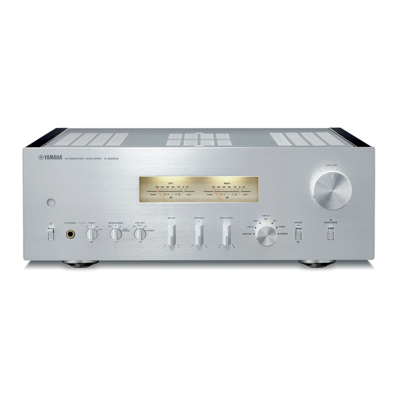
- Page 1 Integrated Amplifier Owner´s Manual...
-
Page 3: Features
Thank you and congratulations on your purchase of this Yamaha product. • You can enjoy the high-quality stereo sound of this integrated amplifier at home. • To use the product properly and safely, we suggest that you read this manual and the “Safety Brochure” thoroughly. -
Page 4: Table Of Contents
Part Names and Functions ....5 Yamaha components..... .21 Connecting the power cable . -
Page 5: Part Names And Functions
Part Names and Functions This section lists the names and describes the function of various parts on the front and rear panels, and the remote control. -
Page 6: Front Panel
Part Names and Functions Front panel A (Power) switch/indicator NOTICE A (Power) switch Power status Indicator If you plan not to use the unit for an extended period of time, be sure to unplug the power plug from the AC Lit brightly outlet. - Page 7 SPEAKERS selector Switches sets of speakers connected to the SPEAKERS L/R CH A and B terminals on the rear panel as follows: OFF: No audio signals will be output from the speakers. A: Audio signals will be output from the set of speakers connected to the A terminals.
- Page 8 Part Names and Functions Front panel BASS control INPUT selector/indicator Adjusts the volume level of the bass range. Selects the input source. The indicator for the selected input source lights up. Audio signals of the selected Adjustable range: −10 dB – 0 – +10 dB input source will be output at the LINE 2 OUT jacks.
- Page 9 Feet Note If the unit is unstable, adjust the height of the feet as • If MAIN DIRECT is selected as the input source, audio needed by rotating them. signals will not be output at the PRE OUT, LINE 2 OUT or PHONES jacks.
-
Page 10: Rear Panel
Part Names and Functions Rear panel BAL (balanced) input jacks AUTO POWER STANDBY switch ON: The unit enters standby mode automatically if it Note is left turned on and not operated for eight hours Set the ATTENUATOR selector and PHASE selector (Auto Power Standby function). - Page 11 PHONO input jacks MAIN IN jacks Connect external components that feature a volume CD input jacks control function so that you can use this unit as a power amplifier. GND (Ground) terminal If you connect your turntable to this unit, ground it to NOTICE the GND terminal.
-
Page 12: Remote Control
Part Names and Functions Remote control Infrared signal transmitter Outputs infrared control signals toward the unit. (➔ page 14) A AMP key Turns on the power to the unit or switches it to standby mode. (➔ page 6) Input select keys Select the input source. - Page 13 LAYER key: Toggles the playback layer of a hybrid super audio CD between “Super audio CD” and “CD.” Note Some Yamaha tuners or CD players might not support the tuner or CD player control keys.
-
Page 14: Installing Batteries In The Remote Control
Part Names and Functions ■ Installing batteries in the remote ■ Operating the remote control control Operate the remote control in the range shown below by pointing it toward the remote control sensor on the front panel of the unit. Remove the battery compartment cover. -
Page 15: Connections
Connections This section explains how to connect the unit to speakers and audio source components. -
Page 16: Connection Diagram
Connections Connection diagram CAUTION Be sure to complete all connections before plugging in the power cable to an AC outlet. (➔ page 22) CD player or network CD player featuring player featuring XLR jacks RCA jacks (➔ page 20) Tuner Speaker A (R channel) (➔... - Page 17 NOTICE If a component is connected to the MAIN IN jacks, the unit’s volume level will be fixed. Therefore, do not connect a CD player or other components that do not feature volume adjustment to the MAIN IN jacks. Otherwise, a loud sound may be emitted, resulting in malfunction of the unit or damage to the speakers.
-
Page 18: Connecting Speakers
Connections Connecting speakers ■ Using speaker cables Note • Because this power amplifier is of the floating balanced type, the following connections are not possible. Remove approximately 10 mm of insulation - Connecting between two “+” (or two “−”) terminals of from the end of each speaker cable, and the left and right channels (Fig. -
Page 19: Using Banana Plug Cables
Bi-wired connection A bi-wired connection separates the woofer from the mid Note and high ranges. Speakers that support bi-wired All connections must be correct: L (left) to L, R (right) to R, “+” to connection feature two pairs of terminals (total four “+”, and “−”... -
Page 20: Balanced Connection
HOT pin at the balanced output jacks on the component. Note • Select NORMAL (pin #2 is HOT) for a Yamaha player. Yamaha AV receiver or • Do not use balanced and unbalanced connections for one other component that features component simultaneously. -
Page 21: Remote Connection
Connect an infrared receiver to the unit’s REMOTE IN/OUT jacks, as shown below. Up to 3 Yamaha components (including this unit) can be set up for remote connection. Rear panel of this unit... -
Page 22: Connecting The Power Cable
Connections Connecting the power cable After all connections are complete, plug the power cable into the AC IN connector of the unit, and then plug the power plug into the AC outlet. Rear panel of this unit Supplied power cable To outlet... -
Page 23: Appendix
Appendix This section lists technical specifications for this unit. -
Page 24: Specifications
Appendix Specifications Rated output power (20 Hz to 20 kHz, 0.07% THD) Maximum input / signal voltage (1 kHz, 0.5% THD) 2-channel driven PHONO (MC)..........2.0 mVrms PHONO (MM)..........50 mVrms [Model for Asia] 8Ω ............90 W + 90 W CD (or similar).......... - Page 25 Channel separation (JEITA, 1 kHz/10 kHz) specifications as of the publishing date. To obtain the PHONO (MC)........66/77 dB or higher latest manual, access the Yamaha website and PHONO (MM).........90/77 dB or higher download the manual file. CD (or similar)/BAL......74/54 dB or higher...
-
Page 26: Block Diagram
Appendix Block diagram TONE CONTROL... -
Page 27: Acoustic Characteristics
Acoustic characteristics ■ Tone control characteristics –2 –4 –6 –8 –10 –12 –14 20k 30k 100k Frequency (Hz) ■ Total harmonic distortion 1.000 0.500 0.200 0.100 0.050 20kHz 0.020 20Hz 0.010 0.005 1kHz 0.002 0.001 Output (W) -
Page 28: Total Harmonic Distortion (Phono)
Appendix ■ Total harmonic distortion (PHONO) 0.05 20Hz 1kHz 20kHz 0.03 0.02 0.01 0.005 0.003 0.002 0.001 0.0005 0.0003 0.0002 0.0001 100µ 200µ 500µ 100m 200m 500m Generator Level (Vrms) -
Page 29: Troubleshooting
Disconnect the power plug from the AC outlet and flashes. There is a problem with the internal contact the nearest authorized Yamaha dealer or — circuitries of this unit. service. When the unit is... -
Page 30: Maintenance
Appendix Problem Cause Remedy page The + and − wires are connected in There is a lack of bass Connect the speaker wires to the correct + and − reverse at the amplifier or the and no ambience. phase. speakers. Incorrect input or output cable Connect the cables properly. - Page 32 Yamaha Global Site https://www.yamaha.com/ Yamaha Downloads https://download.yamaha.com/ Manual Development Group © 2020 Yamaha Corporation Published 01/2020 IPEM-A0 VCV3020 10-1 Nakazawa-cho, Naka-ku, Hamamatsu, 430-8650 Japan...
Need help?
Do you have a question about the A-S2200 and is the answer not in the manual?
Questions and answers