Advertisement
Quick Links
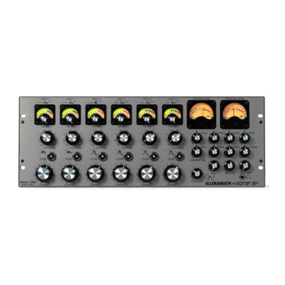
ALLEN&HEATH
WARNING – HIGH VOLTAGES
Power Supply Unit (PSU) work should only
be carried out by qualified personnel.
We recommend that you use an approved Allen & Heath
service centre for all power supply work.
Please contact your local Allen & Heath distributor for more details.
http://www.allen-heath.com/
Advertisement

Related Manuals for ALLEN & HEATH Xone:S6


Summary of Contents for ALLEN & HEATH Xone:S6
- Page 1 ALLEN&HEATH WARNING – HIGH VOLTAGES Power Supply Unit (PSU) work should only be carried out by qualified personnel. We recommend that you use an approved Allen & Heath service centre for all power supply work. Please contact your local Allen & Heath distributor for more details. http://www.allen-heath.com/...
-
Page 2: Service Information
SERVICE INFORMATION Publication AP6297... -
Page 3: Additional Resources
Xone:S6. Please note that the valve circuits from the Xone:V6 are not compatible with the S6 and fitting of these parts should not be attempted. The Xone:S6 MPS7 power supply unit should be used only to power a Xone:S6 console. - Page 4 It has an external linear power supply which should be serviced only by suitably qualified personnel. Operation: The Xone:S6 is an audiophile rotary club mixer. To ensure optimum performance and reliability it should be connected and operated as described in the user guide. Fault finding: Refer to the system block diagram and circuit drawings to follow through the signal path during fault diagnosis.
- Page 5 Contents Log Internal Layout drawing ..........xones6_layout_1.pdf ................ xonev6_options_layout_1.pdf Surface and Main Parts..........xones6_parts_1.pdf ................xonev6_options_parts_1.pdf System Block Diagram ........xones6_blockdiagram_1.pdf Input PCB ..........xones6_003-050_090_input_1.1.pdf Master PCB ..........xones6_003-051_master_2.pdf Mic PCB............xones6_003-052_mic_1.1.pdf Booth PCB............. xones6_003-053_booth_1.pdf Phones PCB ..........xones6_003-054_phones_1.pdf Meter PCB ............xones6_003-471_meter_1.pdf Slave PCB ............xones6_003-472_slave_1.pdf Power Supply PCB........xones6_003-470_power_1.pdf Crossfader Option PCB ....xonev6_options_003-154_xfader_2.pdf EQ Isolator Option PCB ....
- Page 6 XONE:S6 Internal Layout Product ........XONE:S6 Power Supply Versions ..MPS7-100 ..........MPS7-120 ..........MPS7-220 METER PCB XONE:S6 FRONT ..........MPS7-240 003-471 DC Cable Assembly ....002-583 Pack Assembly......003-465 Main Assembly ......003-466 Panel Assembly Front ....003-467 Chassis Assembly ....003-468 PSU Assembly ......003-469...
- Page 7 R105 +30V +28VP 100K 1% 100N 10K 1% 560R 3K3 1% 1K1 1% BC637 47/25 R101 +30VA 10K 1% 270K 220N 680N 100R 47/63 CN1A 100N 10K 1% 2SC2240BL 10K 1% 47K 1% 10K 1% 120R R103 470R 2SC2240BL 47/25 100P/DISK 47K 1% RLY1A...
- Page 8 RIAA disable CH1-3. For RIAA gain and equalisation JP2, JP3, JP4 and JP8 are fitted. This is the factory default setting. To disable RIAA and use these inputs with line sources, remove those jumpers and fit JP1 and JP7 instead. Gain setting CH1-6.
- Page 9 +30VA +30VA +30VA -30VA 220K 330R 10K 1% 100K 10K 1% 3K3 1% 120R 100K 1% VR1A POT18 20KB X2 CD 2SC2240BL 100N VR3A 620K 1% 2SC2240 3K3 1% 100N XLR NC3MBHR20 220R 330N JUMP 2 STRT 30K 2% VP0610L 100/25 100R 470R...
- Page 10 Master output level The output level with MASTER control at maximum position and VU meters reading '0' is +4dBu with JP1 and JP2 fitted. This is the default factory setting. To change this to 0dBu remove JP1 and JP2. Access these jumpers from below the console.
- Page 11 SW1C JUMP 2 STRT BRKT +30V VR1A VR2A JUMP 2 STRT POT18 20KB X2 CD POT18 20KB X2 CD 6K8 1% 6K8 1% VR1B JACK SLIMJACK MET SW6 POT18 20KB X2 POT18 20KB X2 6K8 1% 6K8 1% 10/50 SW1A VR3B 22P/DISK CUE_L_MIX...
- Page 12 Phantom power 30V phantom power is disabled when JP1 is fitted. This is the default factory setting. Plug the jumper on to JP2 instead if you wish to turn phantom power on. 003-052 iss.1...
- Page 13 22P/DISK VR1A 10K 1% 100N POT18 20KB X2 4K7 1% 22P/DISK TL072 100/25 47K 1% 100N BOOTH_L_MIX 22P/DISK 2N7/MYL VR3A 10K 1% 2K2 1% 100K 1% XLR NC3MBHR20 4K7 1% TL072 TL072 100/25 22P/DISK 47N/MYL 47N/MYL TL072+ 47K1% 22P/DISK 2K2 1% 100K 1% 4K7 1% VR2A...
- Page 14 003-053 iss.1...
- Page 15 L_MIX R_MIX 22P/DISK +30VH CUE_L_MIX CUE_R_MIX BOOTH_L_MIX BOOTH_R_MIX MIX_CUE_L MIX_CUE_R VR2A 47K 1% +6.3V +6.3V MIX_CUE_L TIP122 22K 1% 3K3 1% VR1A 22N/MYL 100P/DISK +30V POT18 20KB X2 1N4148 -30V VR3A TL072 BOX 8X2 M 90 DEG 4R7 1W 1N4148 POT18 20KB X2 EARTH SCREW TERMINAL 22P/DISK...
- Page 16 003-054 iss.1...
- Page 17 +V_UNREG NTC1 6800/80 INRUSH SUPP NTC20R FILTERED IEC FUSE HOLDER 20MM MAINS INLET 220/240 1M2 1/2W IEC FILTERED MAINS INLET BR KBU6J CN10 6800/80 -V_UNREG 110/120 CN11 CN12 CN13 CN10 CN14 CN11 +V_PRE_REG CN12 2200/16 2200/16 2200/16 CN13 BR RECTIFIER (AE3477) CN14 +V_UNREG Vout...
- Page 18 003-470 iss.1...
- Page 19 C3_1 C3_2 4.7/20T_S 4.7/20T_S 4.7/20T_S LD1_1 R8_1 LD1_2 R8_2 GND_1 470R GND_2 GND_3 GREEN 470R 470R GREEN GREEN LD2_1 R9_1 LD2_2 R9_2 R6_1 U1_1 R6_2 U1_2 470R GREEN 470R 470R GREEN GREEN LD3_1 R10_1 LD3_2 R10_2 C2_1 C2_2 VREF2 VREF2 VREF2 470R GREEN...
- Page 20 003-471 iss.1...
- Page 21 IN_1_L OUT_1_L IN_2_L OUT_2_L IN_3_L OUT_3_L IN_4_L OUT_4_L IN_5_L OUT_5_L IN_6_L OUT_6_L IN_1_R OUT_1_R IN_2_R OUT_2_R IN_3_R OUT_3_R IN_4_R OUT_4_R IN_5_R OUT_5_R IN_6_R OUT_6_R -30V1 +30V1 -30V2 +30V2 -30V3 +30V 3 -30V4 +30V4 -30V5 +30V5 -30V6 +30V6 +6.3V1 +6.3V2 +6.3V3 +6.3V4 +6.3V5 +6.3V6...
- Page 22 003-472 iss.1...
Need help?
Do you have a question about the Xone:S6 and is the answer not in the manual?
Questions and answers