Table of Contents
Advertisement
Advertisement
Table of Contents

Related Manuals for ALLEN & HEATH XONE 02


Summary of Contents for ALLEN & HEATH XONE 02
- Page 1 T U R N T A B L I S T SERVICE MANUAL Publication AP4501...
- Page 2 Introduction This service manual provides technical information on the Allen & Heath Xone:02 professional DJ mixer. Included is the technical specification, system block diagram, circuit schematics with board layouts, and a spare parts list. Only technically qualified service personnel should carry out service work on the console and its power supply. Whilst we believe the information in this manual to be reliable we do not assume responsibility for inaccuracies.
-
Page 3: Table Of Contents
Contents Important Safety Instructions ...... 4 TECHNICAL DRAWINGS......Key Features..........5 INTERNAL LAYOUT......... D1 Front and Rear Panel Layouts ....5 MAIN/MIC/CONN PCB ......D2 Specifications ..........6 MAIN/MIC/CONN PCB ......D2.1 Xone:02 Block Diagram ......7 MAIN/MIC/CONN CONNECTOR CCT ..D3 Earthing ............ -
Page 4: Important Safety Instructions
Important Safety Instructions – Read First Read instructions: Retain these safety and operating instructions for future reference. Adhere to all warnings printed here and on the console. Follow the operating instructions printed in this User Guide. Do not open: Operate the console with its front and crossfader panels correctly fitted. Disconnect mains power by unplugging the power cord if a panel needs to be removed for servicing. -
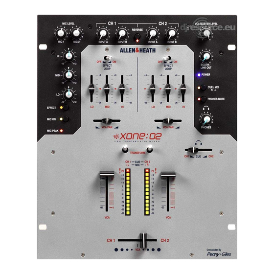
Page 5: Key Features
Key Features • Dual stereo channels with mixable A and B inputs featuring independent level control and channel reverse • A inputs switchable for line and RIAA phono sources • 2 microphone inputs with vocal EQ, effect in/out and independent level control •... -
Page 6: Specifications
Specifications 0dBu = 0.775 Volts rms, +4dBu = 1.23V rms 0dBV = 1 Volt rms, -10dBV = 316mV rms Max output level +23dBu into >2k load Mix System +21dBu into >2k ohm Music EQ 3-Band +6/-26dB +15dBu into >10k ohm 100Hz, 1kHz, 10kHz Headroom Channels... -
Page 7: Xone:02 Block Diagram
XONE:02 BLOCK DIAGRAM VCA MASTER LEVEL GAIN MIC1 3 BAND EQ PEAK VCA CONTROL EFFECT LOOP MIC ON GAIN MIC2 FADER FADER TRANSFORM PHONO/LINE 3 BAND EQ CROSSFADER INPUT A EFFECT LOOP STEREO RIAA CONTOUR CONTOUR CONTOUR LO MID HI INPUT B CUE FADER REVERSE... -
Page 8: Earthing
Earthing The connection to earth (ground) in an audio system is important for two reasons: SAFETY - To protect the operator from high voltage electric shock, and AUDIO PERFORMANCE - To minimise the effect of earth (ground) loops which result in audible hum and buzz, and to shield the audio signals from interference. -
Page 9: Cables And Connections
Cables and Connections The XONE:02 uses professional grade 3 pin XLR, 1/4" TRS jack and RCA PHONO sockets. The following mating plugs may be used: The XLR connector is 3 wire balanced. This has 3 connector pins: Pin 1 = ground (screen), Pin 2 = signal hot (+), Pin 3 = signal cold (-). -
Page 10: Gain And Operating Levels
Gain and Operating Levels It is most important that the system gain and level settings are correctly set. It is well known that many DJs push the gain to maximum with meters peaking hard in the belief that they are getting the best from the system. THIS IS NOT THE CASE ! The best can only be achieved if the system levels are set within the normal operating range and not allowed to peak. -
Page 11: Replacing The Faders
Replacing the Faders The faders on a DJ mixer are heavily used and can suffer considerable wear and tear. The audio design using VCAs prevents clicks and scratchiness as the fader wears. However, the movement can become mechanically stiff or sloppy in time, or become ingrained with dirt. -
Page 12: Tips And Troubleshooting
Tips and Troubleshooting As printed in the User Guide The signal sounds very distorted with For your safety do not remove the EARTH high level and excessive bass. Only plug (ground) connection in the power lead of the turntables needing RIAA equalisation into the console or connected equipment. -
Page 13: Order Codes
Order Codes The following products and parts can be ordered from Allen & Heath or the approved dealer: XONE:92/v XONE:92 6 stereo channel club mixer with MIDI /v = specify voltage XONE:02/v XONE:02 2 channel DJ scratch mixer /v = specify voltage XONE:32/v XONE:32 3 channel DJ mixer /v = specify voltage... -
Page 14: Ordering An Assembly
ORDERING AN ASSEMBLY The following assemblies for the XONE:02 are supplied fully tested. Please quote the description and order code for the part required. Printed circuit board (PCB) assemblies: DESCRIPTION ORDER CODE Main/Mic/Conn PCB assembly 002-763 Master/Mains/Meters PCB assembly 002-764 IDC connector harnesses: ORDER CODE DESCRIPTION... -
Page 15: Ordering A Xone:02 Spares Kit
ORDERING A XONE:02 SPARES KIT It is recommended that the spares kit order code 002-766 is held and maintained by the service agent to enable in-field service repairs to the XONE:02 independent of the ALLEN & HEATH factory. Commonly available items such as resistors, capacitors, tools and soldering equipment are not included. - Page 16 POT ALPS 14MM 20KKX2 ST (203K) AI8007 SWITCH 2PCO LATCH SINGLE AL0162 JACK SKT STEREO SW PCB CHROME AL0328 SWITCH 4PCO LATCH AL0333 SWITCH ALPS 6PCO LATCH AL0354 XLR FEM 3PIN VERT PCB AL2410 XLR MALE 3PIN VERT PCB AL2411 JACK SKT 1/4"...
- Page 17 TRANSISTOR 2SB737 PNP AE8069 Miscellaneous: DESCRIPTION ORDER CODE PRESET 22K CARBON HOR ADJUST AC3980 Power Supply: DESCRIPTION ORDER CODE MAINS LEAD IEC-2PIN EURO AH0205 MAINS LEAD IEC-3PIN UK AH0206 MAINS LEAD IEC-3PIN C33 USA AH0323 SWITCH MAINS PCB 10A AL3338 MAINS INLET IEC FILTER PCB 3PIN AL3458 FUSE 20MM 500MA A/SURGE...
-
Page 18: Technical Drawings
Technical Drawings The following section includes the full set of technical drawings associated with the XONE:02. The MAP DRAWINGS show the interconnection between the various circuit assemblies. The PCB and CIRCUIT drawings show the details for each assembly. Option and assignment links are marked where appropriate. - Page 22 +VCON +VCON +V_CON_C R303 R305 10R PF 6K8 1% 6K8 1% 10/50 XLR NC3FAV20 100/25 VR1A 22P/DISK 100N 100N C187 10KZ 22K 1% 100N 220/10 330P 2SB737 NE5532 NE5532 NE5532 TL072 TL072 2SB737 MIC_1_O/P_C 100/25 -VCON -V_CON_C NE5532 10R PF 10/50 R307 R308...
- Page 23 +VCON +VCON +V_CON_C R303 R305 10R PF 6K8 1% 6K8 1% 10/50 XLR NC3FAV20 100/25 VR1A 22P/DISK 100N 100N C187 10KZ 22K 1% 100N 220/10 330P 2SB737 NE5532 NE5532 NE5532 TL072 TL072 2SB737 MIC_1_O/P_C 100/25 -VCON -V_CON_C NE5532 10R PF 10/50 R307 R308...
- Page 24 C102 R138 22K 1% 6N8/MYL EQ SUB PCB 1N5/MYL 1N5/MYL R113 CN1_3 TL072 270R R137 VR15A R105 22K 1% 2K2 1% VR17A R106 R117 R146 +VEQL 270R 10R PF 30K 2% 30K 2% 47/25 VR14A U10C U11C CN16 R121 22P/DISK EQIN-CH1-L VR14B 22P/DISK...
- Page 25 C102 R138 22K 1% 6N8/MYL EQ SUB PCB 1N5/MYL 1N5/MYL R113 CN1_3 TL072 270R R137 VR15A R105 22K 1% 2K2 1% VR17A R106 R117 R146 +VEQL 270R 10R PF 30K 2% 30K 2% 47/25 VR14A U10C U11C CN16 R121 22P/DISK EQIN-CH1-L VR14B 22P/DISK...
- Page 26 VR11 R183 R313 22K AC3980 330K VR8A 8K2 1% 10K 1% YELLOW R312 GREEN 20KB C131 C132 C134 U31A SW4A SW3A C133 100P R135 C189 R154 20K 1% MIC_1_O/P_M 100K SW4B R153 20K 1% U16A 10/50 U17B MIC_O/P_MIX_M THAT 2155 100K MIC_2_O/P_M TL072...
- Page 27 VR11 R183 R313 22K AC3980 330K VR8A 8K2 1% 10K 1% YELLOW R312 GREEN 20KB C131 C132 C134 U31A SW4A SW3A C133 100P R135 C189 R154 20K 1% MIC_1_O/P_M 100K SW4B R153 20K 1% U16A 10/50 U17B MIC_O/P_MIX_M THAT 2155 100K MIC_2_O/P_M TL072...
- Page 28 C139 100N 275V CN21 C138 100N 275V C143 C144 C145 SIL 2 M STRT 2KBP206 L_GND 10/400 10/400 10/400 CHOKE 20MH C140 C146 C141 100N 275V 4.7uH 2N2 250V/PEM 100N 275V L_GND C147 C137 R206 PHONES+V C142 4.7uH 100N 63V/PE 4R7 1W C152 C153...
- Page 29 C139 100N 275V CN21 C138 100N 275V C143 C144 C145 SIL 2 M STRT 2KBP206 L_GND 10/400 10/400 10/400 CHOKE 20MH C140 C146 C141 100N 275V 4.7uH 2N2 250V/PEM 100N 275V L_GND C147 C137 R206 PHONES+V C142 4.7uH 100N 63V/PE 4R7 1W C152 C153...
- Page 30 V_REF +3.7V U20C U21C 100N 100N V_REF +3.7V 10R PF TLC072C TLC072C 47/25 U22C U23C 1N4148 -0.16V VR25A 20KK TL072 TL072 R232 CHANNEL 1 FADER CONNECTOR 47/25 100K 1% R236 10R PF R187 330R CH1 FADER CNTRL 10K 1% U20B R299 TLC072C C127...
- Page 31 V_REF +3.7V U20C U21C 100N 100N V_REF +3.7V 10R PF TLC072C TLC072C 47/25 U22C U23C 1N4148 -0.16V VR25A 20KK TL072 TL072 R232 CHANNEL 1 FADER CONNECTOR 47/25 100K 1% R236 10R PF R187 330R CH1 FADER CNTRL 10K 1% U20B R299 TLC072C C127...
- Page 32 C171 L_MIX 22P/DISK 100P/DISK R272 R217 J111 10K 1% 30K 2% L_FX_MIX R261 C179 L_MIX R277 LEFT_O/P_- 8K2 1% U28A U25A J111 TL072 47/25 R213 TL072 R_MIX MIX_OUT_L R269 30K 2% R281 R285 10K 1% 2K2 1% 100K R263 R253 VCA1_LEFT J111 8K2 1%...
- Page 33 C171 L_MIX 22P/DISK 100P/DISK R272 R217 J111 10K 1% 30K 2% L_FX_MIX R261 C179 L_MIX R277 LEFT_O/P_- 8K2 1% U28A U25A J111 TL072 47/25 R213 TL072 R_MIX MIX_OUT_L R269 30K 2% R281 R285 10K 1% 2K2 1% 100K R263 R253 VCA1_LEFT J111 8K2 1%...
- Page 35 YELLOW SW5A METER_LEFT METER_RIGHT CN16 CN17 SW6A EQOUT-CH1-L PHONES-V PHONES+V EQOUT-CH1-R SW5B EQOUT-CH2-R HM_GND VR11A EQOUT-CH2-L BOX 5X2 M 90 DEG VR13B VR13A 1N4148 47/25 PHONES_L SIL 6 F 90 DEG SIL 6 M STRT 47/25 POT GANGED 100K LA6515 MIX_OUT_L SW5F EQOUT-CH1-L...
- Page 36 PHONES+V_L +VML PHONES+V_R +VMR 10R PF 10R PF 10/50 10/50 LM339 LM339 LM339 LM339 LM339 LM339 PHONES-V_L -VML PHONES-V_R -VMR 10R PF 10R PF LEFT METER PCB RIGHT METER PCB +VML +VMR CN21 IEC FILTERED MAINS INLET HM_GND_L HM_GND_R 680R 820R 1% 680R 820R 1%...
Need help?
Do you have a question about the XONE 02 and is the answer not in the manual?
Questions and answers