Table of Contents
Advertisement
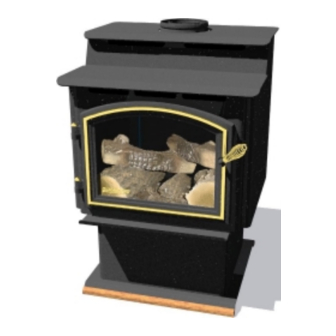
DV-40 STEP TOP DIRECT VENT FREESTANDING GAS STOVE (DV-40 STEP)
INSTALLATION, OPERATION, VENTING AND MAINTENANCE INSTRUCTIONS
CONGRATULATIONS! You are now the proud owner of one of the finest gas stoves on the market - the QUADRA-FIRE.
If the information in this manual is not followed exactly a fire or explosion may result, causing
property damage, personal injury or death.
DO NOT store or use gasoline or other flammable vapors and liquids in the vicinity of this or any other
appliance.
• Extinguish any open flame.
• Open windows.
• Do not try to light any appliance.
• Do not touch any electric switch.
• Do not use any telephone in your building.
This appliance may be installed in an aftermarket permanently located, manufactured (mobile)
home, where not prohibited by local codes.
This appliance is only for use with the type of gas indicated on the rating plate. This appliance
is not convertible for use with other gases, unless a certified kit is used.
401 N. Wynne Street
Colville, WA 99114
N o r t h A m e r i c a ' s B e s t
WARNING
FOR YOUR SAFETY
WHAT TO DO IF YOU SMELL GAS
Revised 04/19/1998 Part #250-4320 & #842-3220
SAVE THESE INSTRUCTIONS
Page 1
• Immediately call your gas supplier from a neighbor's phone.
• Follow the gas supplier's instructions.
• If you cannot reach your gas supplier, call the fire department.
• Installation and service must be performed by a qualified
installer, service agency, or the gas supplier.
Revised (8/98)
www.aladdinhearth.com
aladdin@aladdinhearth.com
Advertisement
Table of Contents
Troubleshooting

Related Manuals for Quadra-Fire DV-40


Summary of Contents for Quadra-Fire DV-40
-
Page 1: For Your Safety
INSTALLATION, OPERATION, VENTING AND MAINTENANCE INSTRUCTIONS Revised (8/98) CONGRATULATIONS! You are now the proud owner of one of the finest gas stoves on the market - the QUADRA-FIRE. WARNING If the information in this manual is not followed exactly a fire or explosion may result, causing property damage, personal injury or death. -
Page 2: Table Of Contents
TABLE OF CONTENTS PAGE Safety Label ............................. 3 Safety Notices ............................4 Specifications and Listings ........................5 Dimensions .............................. 6 Unpacking the stove ..........................7 Thermostat installation..........................9 Planning your installation ........................10 Simpson DuraVent Parts list ........................12 Clearances to combustibles ........................14 Hearth requirements .......................... -
Page 3: Safety Label
DV-40 STEP SAFETY LABEL (FOUND ON PULL-OUT ON BACK OF STOVE) Page 3... -
Page 4: Safety Notices
SAFETY NOTICES This stove should be installed only by a qualified installer. It is approved for installation in a bedroom. Bedroom installation in Canada requires that stove be hooked to a thermostat. The stove must be electrically grounded in accordance with local codes, or the latest edition of the National Electric Code. -
Page 5: Specifications And Listings
26,000 BTUH 27,000 BTUH BTU output rating (low)* 22,100 BTUH 23,000 BTUH Steady State Efficiency* *Maximum vent, blower off LISTINGS The Quadra-Fire DV-40 Step is listed to ANSI Z21.88/CSA 2.331998-CAN/CGA 2.17-M91 UL307b by Omni-Test Laboratories, Inc., Beaverton, Oregon. Page 5... -
Page 6: Dimensions
DIMENSIONS LEG MODEL 23 3/16" [589m m ] 21 1/2" [546m m ] 24 5/8" [625m m ] 12 9/16" [319m m ] 12 5/16" [313m m ] 6 1/8" [156m m ] 24 7/8" [632m m ] 20 5/8" [524m m ] PEDESTAL MODEL 23 3/16"... -
Page 7: Unpacking The Stove
Between the firebox bottom and pallet is an accessories box containing logs, nuggets, touch-up paint, an allen key, and instructions for installation of legs or pedestal. DV-40 STEP LEG ADAPTER ASSEMBLY INSTRUCTIONS Remove door from unit and log box located between stove and pallet. - Page 8 DV40 STEP PEDESTAL INSTALLATION INSTRUCTIONS Remove log box located between stove and pallet Remove door from unit. Remove pallet mounting bolts from underneath pallet and remove stove from pallet WITH FRONT DOOR REMOVED lay unit down on it’s front for easy access to bottom.(Fig. 1) NOTE: The right and left logs are fastened to the stove.
-
Page 9: Thermostat Installation
THERMOSTAT INSTALLATION If desired, a thermostat may be installed to regulate the Quadra-Fire DV-40 Step. It is important to use a thermostat designed for millivolt operation. Do not connect this stove to a thermostat serving any other appliance. Bedroom installation in Canada requires this stove to be hooked to a thermostat. -
Page 10: Planning Your Installation
PLANNING YOUR INSTALLATION There are four types of direct vent system installations approved for use with the DV40 Step. It is very important to maintain a balance between the combustion air intake and the flue gas exhaust venting system. The types of installation are: Horizontal Termination (Figure 1, Pg. - Page 11 FOR HORIZONTAL TERMINATIONS USE ONLY DURAVENT PART # 985 OR ALADDIN HEARTH PRODUCTS PART #HHW2 (See * in Figure 1 below). FOR VERTICAL TERMINATIONS USE DURAVENT PART #991. WALL THIMBLE HORIZONTAL VERTICAL TERMINATION TERMINATION Part #991 90 ELBOW PART #985 STORM COLLAR FLASHING PIPE LENGTH...
-
Page 12: Simpson Duravent Parts List
Decorative brass and chrome trim kits are available for both wall thimbles and ceiling support boxes. Snorkel terminations are available for applications which may require a vertical rise on the building exterior. The following components have been approved for use with the Quadra-Fire DV40 Step. - Page 13 SIMPSON DURA-VENT PARTS LIST ( CONT BASIC KITS The standard termination kit (Kit 0970A) includes the following: 990B 1 each 90° Black Elbow 1 each Round Ceiling Support/Wall Thimble 1 each High Wind Horizontal Termination Cap NOTE: The above kit is not a complete termination system. You will need to order the straight pipe lengths needed to complete the installation.
-
Page 14: Clearances To Combustibles
CLEARANCES TO COMBUSTIBLES Minimum clearances to combustible materials from stove body: A Left & Right of Stove (One Wall) 9” (225mm) B Back wall (to Pipe) 8” (200mm) C Top of unit (from Stove Top) 24” (600mm) D Corner clearance* 1”... -
Page 15: Venting Graph
HOW TO USE VENT GRAPH Measure the distance from the top of stove to the center of the 90° elbow. On the graph below, draw a horizontal line from that measurement on the vertical axis across until it intersects with the slanted line. -
Page 16: Venting Instructions
Vent venting components may be used. DO NOT USE FIELD-FABRICATED VENTING COMPONENTS. The Quadra-Fire DV40 Step is approved to be vented either through the side wall or vertically through the roof. You may vent through a Class A or masonry chimney if a Simpson Dura-Vent adapter is used (for USA installations only). -
Page 17: Venting
VENTING NOTE: THIS STOVE IS A DIRECT VENT HEATER. ALL COMBUSTION AIR MUST COME DIRECTLY FROM THE OUTSIDE OF THE BUILDING. THE VENT PIPE FOR THIS UNIT CONSISTS OF AN INNER AND AN OUTER PIPE. THE INNER PIPE CARRIES THE STOVE EXHAUST OUT OF THE SYSTEM, AND THE OUTER PIPE BRINGS FRESH COMBUSTION AIR INTO THE STOVE. -
Page 18: Horizontal Installation
HORIZONTAL INSTALLATION NOTE: RESTRICTOR STRAP IS REQUIRED IF HORIZONTAL VENTING CONFIGURATION HAS 10’ OR GREATER OF VERTICAL RISE AND NOT MORE THAN ONE 90 DEGREE ELBOW. Step 1. Set the gas stove in its desired location. Check to determine if wall studs or roof rafters are in the way when the venting system is attached. - Page 19 HORIZONTAL INSTALLATION ( CONT Step 3. With the adapter and pipe attached to the stove, slide the stove into its correct location, maintaining minimum clearance to combustibles, and mark the wall for a 10” x 10” (254mm x 254mm) square hole.
- Page 20 HORIZONTAL INSTALLATION ( CONT Step 4. Position the horizontal vent termination in the center of the 10” (254mm) square hole, and attach to the exterior wall with the four wood screws provided. Before attaching the Vent Termination to the exterior wall, run a bead of non-hardening mastic around its outside edges, so as to make a seal between it and the wall.
- Page 21 HORIZONTAL INSTALLATION ( CONT Step 5. Before connecting the horizontal run of vent pipe to the vent termination, slide the black decorative wall thimble cover over the vent pipe. Step 6. Slide the stove and vent assembly towards the wall, carefully inserting the vent pipe into the vent cap assembly.
-
Page 22: Vertical Terminations
VERTICAL TERMINATIONS USING GS SERIES PIPE Step 1. Check the installation instructions for required 2 inch clearances (air space) to combustibles when passing through ceilings, walls, roofs, enclosures, attic rafters, or other nearby combustible surfaces. (See page 24, FIG. 16) Do not pack air space with insulation. Check the instructions below for maximum vertical rise of the venting system, and any maximum horizontal offset limitations (Figure 11). - Page 23 VERTICAL TERMINATIONS ( CONT USING GS SERIES PIPE (CONT.) Step 4. Assemble the desired lengths of GS pipe and elbows necessary to reach from the stove up through the round support box. Insure that all pipe and elbow connections are in their fully twist- locked position.
- Page 24 VERTICAL TERMINATIONS ( CONT USING GS SERIES PIPE (CONT.) Step 7. Continue to assemble pipe sections until the height of the vent cap (H) (Figure 15) meets the minimum code requirements described in code requirements as outlined in the current CAN/ CGA-Bl49 Installation Codes (in Canada), the National Fuel Gas Code NFPA 54/ANSI Z223.1 (in USA), or local codes.
-
Page 25: Cathedral Ceiling Installation
VERTICAL TERMINATIONS ( CONT CATHEDRAL CEILING INSTALLATION Step 1. Follow installation Steps 1 and 2 under vertical termination section. Step 2. Using the plumb-bob, mark the centerline of the venting system on the ceiling, and drill a small hole through the ceiling and roof at this point. From the roof, locate the drill hole and mark the outline of the cathedral ceiling support box. -
Page 26: Class A Metal Chimney Installation
VERTICAL TERMINATIONS ( CONT INSTALLATION INTO A CLASS A METAL CHIMNEY NOTE: Have the existing installation inspected by a qualified chimney sweep or professional installer prior to converting to direct vent. The existing chimney system must be in serviceable condition and functionally sound and clean. -
Page 27: Existing Masonry Chimney Installation
VERTICAL TERMINATIONS ( CONT INSTALLATION INTO AN EXISTING MASONRY CHIMNEY Step 1. Before cutting any holes, assemble the desired sections of direct vent pipe to determine the center of the masonry penetration. Step 2. Once the center point of the penetration has been determined, cut a 6”... - Page 28 VERTICAL TERMINATIONS ( CONT INSTALLATION INTO AN EXISTING MASONRY CHIMNEY (CONT.) Step 5. Connect the flex liner to the top adapter using three sheet metal screws (see Figure 20). Step 6. Feed the flex liner through the flashing into the chimney. Carefully feed the flex liner down the chimney to the bottom and out the opening in the masonry wall, forming an angle to line up the flex liner with the vent...
- Page 29 VERTICAL TERMINATIONS ( CONT INSTALLATION INTO AN EXISTING MASONRY CHIMNEY (CONT.) Step 9. Attach the flex to the retro connector. Use three sheet metal screws to attach the flex liner to the connector (Figure 26). Mount the retro connector to the masonry wall using masonry bolts.
-
Page 30: Gas Line Connection
GAS LINE CONNECTION Gas line connection can be made near the lower rear of the stove (3/8” gas hookup). You must supply a shutoff valve installed in a visible location within 3’ (914 mm) of the stove. Before hooking up the stove to the gas supply, be sure that the stove you are installing is designed for the type of gas being supplied to it. -
Page 31: High Altitude Operation
HIGH ALTITUDE OPERATION In Canada, this unit is approved from 0 to 4500 feet above sea level. Installation of this stove at altitudes above 4500 feet is subject to field test of the individual installation and approval by the local authority having jurisdiction. -
Page 32: Gas Conversion Instructions (Ng To Lp Or Lp To Ng)
GAS CONVERSION INSTRUCTIONS FOR LP AND NG WARNING ! The installation of this conversion kit must only be undertaken by a qualified and certified gas appliance installer. CAUTION: DISCONNECT ANY ELECTRICAL CORDS AND TURN OFF GAS SUPPLY TO UNIT BEFORE PROCEEDING. Valve Regulator Tower Turn control knob to the OFF position and shut off the gas supply to the valve. - Page 33 CONVERSION INSTRUCTIONS CONT Burner Orifice Replacement Remove the right top log bracket using a Phillips screwdriver (Screws are accessed through rectangular hole in bracket.) See Fig. 4, Pg. 37 (Labeled “Peg in right log bracket”) Remove the right and left side log retaining brackets (one per side). (Top of log and firebox side.) Carefully lift logs vertically off alignment pegs and place in a safe area out of the way of traffic.
- Page 34 CONVERSION INSTRUCTIONS (CONT.) Pilot Tower Orifice Replacement Loosen (CCW rotation) and remove pilot target hex fitting with a 7/16” end wrench as shown in figure FIG. A Remove the currently installed orifice with a pair of needlenose pliers or other means as shown in figure B.
-
Page 35: Log Installation
CONVERSION INSTRUCTIONS, (CONT.) Lighting and pressure testing Apply gas to system and re-light appliance according to lighting instructions. With the main burner “ON”, test the new pressure regulator assembly for leaks using soap bubbles or a gas leak detector. Re-light the main burner in both the HI and LO positions and verify proper burner ignition and operation. - Page 36 LOG INSTALLATION, CONTINUED FIGURE 1 PLACE PEG HOLES IN LOG #23 OVER PEGS IN CENTER BURNER PAN. If damage has occurred to right or left base log, and replacement is necessary, removal is illustrated in conversion instruction steps 5-7. FIGURE 2 DO NOT ALLOW NUGGETS ON BACKSIDE OF THIS PLATE.
- Page 37 LOG INSTALLATION, CONTINUED FIGURE 4 RIGHT TOP LOG #24. PEG HOLE PEG IN RIGHT LOG BRACKET NOTCH FOR RIGHT TOP LOG FINISHED LOG SET CAUTION ! Light appliance with door open to insure there is no hesitation or delay of flame transfer through nugget bed.
-
Page 38: First Fire
FIRST FIRE NOTE: Never operate this stove with the door open. Before first firing the stove, read the owner’s manual to familiarize yourself with the stove’s features, controls, and cautions for operation. Remove all labels from glass before operating this stove for the first time. Plug power cord into a properly installed outlet for blower operation. -
Page 39: Lighting Instructions
LIGHTING INSTRUCTIONS (LOCATED ON PULL-UP AT LEFT REAR OF STOVE) Page 39... -
Page 40: Pressure Testing
PRESSURE TESTING This appliance must be disconnected from the gas supply piping system if any testing is done to the system that exceeds the test pressure of 1/2 PSIG. If the test pressure is less than or equal to 1/2 PSIG, then this appliance must be isolated from the piping system by closing its individual shutoff valve. -
Page 41: Maintenance
MAINTENANCE CLEANING AND INSPECTION OF VENTING SYSTEM At least once yearly, preferably before the heating season, have the insert and venting system cleaned and inspected by a qualified service person. This will insure proper and safe operation throughout the year. CLEANING THE BURNER TUBES PILOT HOOD Turn off pilot light. -
Page 42: Blower
BLOWER CLEANING AND/OR REPLACEMENT Cleaning is recommended at least once yearly or as needed. 1. Disconnect power and turn off gas supply. 2. Unplug blower at molex connector (see “A” below). 3. Remove two screws on back plate of blower compartment. 4. -
Page 43: Schematics
SCHEMATICS Orange=O Black=B W h i t e = W Red=R Green=G Page 43... -
Page 44: Blower And Snap Disc Replacement
SNAP DISC REPLACEMENT 1. Disconnect power from unit and turn off gas supply. 2. Remove four screws as shown in figure below and take off rear heatshield. 3. Remove all wires attached to snap disc. 4. Remove set screws holding snap disc in place. 5. -
Page 45: Accessories/Replacement Parts
ACCESSORIES These may be ordered through your Quadra-Fire dealer. 812-2880 Thermostat, manual 811-0520 Thermostat, programable 844-0100 Thermostatic Remote Control REPLACEMENT PARTS 842-3200 Baffle 842-3230 Black door with gold trim ring 842-3210 Blower assembly, 160 cfm 842-0380 Blower cord, 6 foot... -
Page 46: Pilot Replacement Instructions
PILOT REPLACEMENT INSTRUCTIONS If log set is installed, remove the top logs, center log, ember nuggets and left base log. If log set is not installed remove only left base log. Remove six #8/32 screws that hold the center burner pan in place. Lift burner pan out of firebox and set aside. -
Page 47: Flame Troubleshooting
FLAME TROUBLESHOOTING NOTE: It is important to understand that the flame and glow in this appliance was designed to resemble a matured wood flame. The amount of charcoal nuggets and glowing ember limit the amount of flame height attainable. This appliance will not have the typical tall yellow gas unit flames. (Avg. flame height 3- 5”). - Page 48 Flame Troubleshooting, cont. 2. If vertically vented, a restrictor strap is required to reduce the volume of combustion air, which in turn will raise the flame height. Restrictor Strap NOTE: This plate rests on damper shaft. FIG. B 3. If vented vertically with a horizontal run included; determine if the rise to run is close to the venting graft maximum, i.e.
-
Page 49: Pilot Troubleshooting
If this does not remedy the problem you may have a faulty piezo or cracked ceramic on the electrode. Call your Quadra-Fire dealer. If there is a spark: Try to light the pilot with a match (use caution when doing this.) First open door and smell for gas, then toss lit match below pilot. - Page 50 FLAMES Thermopile Pilot Hood (Millivolt Generator) Thermocouple PILOT ASSEMBLY SHOWING FLAME PROPERLY ADJUSTED. Page 50...
-
Page 51: Warranty
Aladdin Hearth Products. This new Quadra-Fire product must be installed by a competent, authorized service contractor. It must be installed and operated at all times in accordance with the Installation, Operation and Maintenance Instructions furnished with this product, as well as any applicable local and national codes.
Need help?
Do you have a question about the DV-40 and is the answer not in the manual?
Questions and answers