Table of Contents
Advertisement
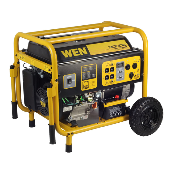
MODEL 9000E
420 cc Generator
Item # 56877
Owner's Manual
Manual del Propietario
Questions? Problems?
Please call our customer help line:
(800) 232-1195
M-F 8-5 CST
FEATURES
• 9000 Surge Watt Output
• 7000 Rated Watt Output
• Powerful Enough to Run Essential Appliances During Power Outages
• 120 and 240 Volt AC Outputs
• Low Oil Automatic Shutoff
• Circuit Breaker for Overload Protection
• 6.5 Gallon Fuel Tank Capacity
• Digital Engine Hour Counter
• Electric Starter
• Cigarette Lighter Style 12V DC Outlet
• Spark Arrester
• Meets EPA Emission Standards
Advertisement
Table of Contents

Subscribe to Our Youtube Channel
Related Manuals for Wen 56877


Summary of Contents for Wen 56877
- Page 1 MODEL 9000E 420 cc Generator Item # 56877 Owner’s Manual Manual del Propietario Questions? Problems? Please call our customer help line: (800) 232-1195 M-F 8-5 CST FEATURES • 9000 Surge Watt Output • 7000 Rated Watt Output • Powerful Enough to Run Essential Appliances During Power Outages •...
-
Page 2: Generator Identification
GENERATOR IDENTIFICATION For information and questions, please contact the Customer Service Help Line by calling 800-232- 1195. Certain information will be requested by the Customer Service Representative and to facilitate that, please fill in the information below. Refer to the illustration below for the location of Serial Number. Record generator information in the spaces provided below. -
Page 3: Table Of Contents
TABLE OF CONTENTS GENERATOR IDENTIFICATION ....................i SERVICE RECORD ......................... i INTRODUCTION ..........................1 SAFETY INFORMATION ......................2 GENERAL SAFETY PROCEDURES ................... 3 IMPORTANT SAFETY INSTRUCTIONS ................... 5 PACKAGE CONTENTS ......................... 6 GENERATOR COMPONENTS ..................... 7 ASSEMBLY ............................8 GENERATOR PREPARATION ....................11 Using the Generator for the First Time .................. -
Page 4: Introduction
INTRODUCTION ® Thank You for Purchasing a WEN Product. This manual provides information regarding the safe operation and maintenance of this product. Every effort has been made to ensure the accuracy of the information in this manual. ® reserves the right to change this product and specifications at any time without prior notice. -
Page 5: Safety Information
SAFETY INFORMATION Before operating this generator read and observe all warnings, cautions, and instructions on this sheet, on the generator, and in the Owner’s Manual. NOTE: The following safety information is not meant to cover all possible conditions and situations that may occur. Read the entire Owner’s Manual for safety and operating instructions. -
Page 6: General Safety Procedures
GENERAL SAFETY PROCEDURES For any questions regarding the hazard and safety notices listed in this manual or on the (800) 232-1195 M-F 8-5 CST product, please call before using the generator. DANGER : CARBON MONOXIDE. Using a generator indoors CAN KILL YOU IN MINUTES. - Page 7 WARNING : This generator produces powerful voltage, which can result in electrocution. • ALWAYS ground the generator before using it (see the “Ground the Generator” portion of the “GENERATOR PREPARATION” section). • Generator should only be plugged into electrical devices, either directly or with an extension cord.
-
Page 8: Important Safety Instructions
IMPORTANT SAFETY INSTRUCTIONS • SAVE THESE INSTRUCTIONS – This manual contains important instructions for ® 9000E generator that should be followed during installation and maintenance of the generator. • Generators vibrate in normal use. During and after the use of the generator, inspect the generator as well as extension and power supply cords connected to it for damage resulting from vibration. -
Page 9: Package Contents
PACKAGE CONTENTS Your generator comes with the items listed below. Please check to see that all of the following items are included with your generator. (800) 232-1195 If there are any damaged or missing items, please call M-F 8-5 CST for customer service. -
Page 10: Generator Components
GENERATOR COMPONENTS Please familiarize yourself with the locations and functions of the various components and controls of your generator. (1) Fuel Cap- Access to the fuel tank for (9) 10" Never Flat Wheels- For easy adding fuel. transport. (2) Power Indicator-Green lights that turn (10) 12V Battery on to indicate the output of power to (11) 120 Volt AC Duplex Receptacle- To... -
Page 11: Assembly
ASSEMBLY In order to best protect the generator while in the package, this product comes with some components disassembled. Please complete the following assembly steps before proceeding to use the generator. For ease of assembly, we recommend attaching the components in the order listed in this manual. -
Page 12: Attach Handles
Attach Handles The handles attach to the generator frame on the same side as the recoil starter (Left side when facing control panel). To attach the handles to the generator frame, perform the following steps: 1. Take one handle and line up the holes in the handle bracket with the holes on the generator frame. - Page 13 At this point, the generator assembly is complete. Gently remove the generator from the wood block. Figure 3- supporting the generator Only this side toward Axle Figure 4- wheel installation...
-
Page 14: Generator Preparation
GENERATOR PREPARATION Using the Generator for the First Time The following section describes steps necessary to prepare the generator for use. If after (800) reading this section, you are unsure about how to perform any of the steps please call 232-1195 M-F 8-5 CST for customer service. -
Page 15: Step 2- Add Gasoline
Step 2- Add Gasoline WARNING: This generator may emit highly flammable and explosive gasoline vapors, which can cause severe burns or even death if ignited. A nearby open flame can lead to explosion even if not directly in contact with gasoline. •... -
Page 16: Step 3- Ground The Generator
Step 3- Ground the Generator WARNING: Failure to properly ground the generator can result in electrocution. Ground the generator by tightening the grounding nut against grounding wire (see figure 9). A generally acceptable grounding wire is a No. 12 AWG (American Wire Gauge) stranded copper wire. -
Page 17: Step 4- Connect The Battery
Step 4 – Connect the Battery WARNING: Battery gives off explosive hydrogen gas. • Keep battery away from spark, flame, or cigarette. • Do not connect or disconnect battery while generator is running. • Service or use battery only in well ventilated areas. WARNING: Battery contains sulfuric acid. -
Page 18: Starting The Generator
STARTING THE GENERATOR Before starting the generator, make sure you have read and performed the steps in the “Generator Preparation” section of this manual. If you are unsure about how to perform any (800) 232-1195 M-F 8-5 CST of the steps in this manual please call for customer service. - Page 19 Electric Start To start the generator using the electric start function, perform the following steps: 1. Make sure no electrical devices are connected to the generator. Such devices can make it difficult for the engine to start. 2. Check that the generator is properly grounded (see Figure 9, “Ground the Generator”). 3.
-
Page 20: Subsequent Starting Of The Generator
Figure 10- Fuel Valve in the “on” position Figure 11- Pull choke out for closed position. Push in for open position. Figure 12- Pulling the start cord SUBSEQUENT STARTING OF THE GENERATOR If this is not the first time using the generator, user should take the following steps to prepare it for operation. -
Page 21: Step 3- Ground The Generator
WARNING: This generator may emit highly flammable and explosive gasoline vapors, which can cause severe burns or even death if ignited. A nearby open flame can lead to explosion even if not directly in contact with fuel. • Do not operate near open flame. •... -
Page 22: Using The Generator
USING THE GENERATOR WARNING: When this generator is used to supply a building wiring system: Generator must be installed by a qualified electrician and connected to a transfer switch as a separately derived system in accordance with the National Electrical Code, NFPA 70. The generator shall be connected to a transfer switch that switches all conductors other than the equipment grounding conductor. - Page 23 When the rated wattage requirement of each electrical device has been determined, add these numbers to find the total rated wattage needed. If this number exceeds the rated wattage of the generator, DO NOT connect all these devices. Select a combination of electrical devices, which has a total rated wattage lower than or equal to the rated wattage of the generator.
- Page 24 2. Push in the circuit reset buttons to the “ON” position (NOTE: They may be pushed in already). 3. The power indicator lights will light accordingly as the Volt Selector is selected. They light up when the receptacles receive power. In the case of the 240/120 Volt receptacle, both lights MUST light up for 240/120 Volts of power.
-
Page 25: Dc Usage
SOME NOTES ABOUT POWER CORDS Long or thin cords can drain the power provided to an electrical device by the generator. When using such cords, allow for a slightly higher rated wattage requirement by the electrical device. See Figure 16 for recommended cords based on the power requirement of the electrical device. Device Requirements Max. -
Page 26: Stopping The Generator
STOPPING THE GENERATOR To stop the generator: 1. Turn off all electrical devices prior to unplugging them from the generator. Unplugging running devices can cause damage to the generator. 2. Turn the engine switch to the “OFF” position. 3. Turn the fuel valve to the “OFF” (horizontal) position. WARNING: Allow the generator to cool for several minutes before touching areas that become hot during use. -
Page 27: Maintenance / Care
MAINTENANCE / CARE Proper routine maintenance of your generator will help prolong the life of your machine. Please perform maintenance checks and operations according the schedule in figure 17. If you have questions about any of the maintenance procedures listed in this manual, please call (800) 232-1195 M-F 8-5CST. -
Page 28: Changing/ Adding Oil
Figure 18- Checking the oil Changing/ Adding Oil Change the oil according to the maintenance schedule in figure 17. Change the oil when the engine is warm. This will allow for complete drainage. Change oil more often if operating under heavy load or high ambient temperatures. -
Page 29: Air Cleaner Maintenance
Air Cleaner Maintenance Routine maintenance of the air cleaner helps maintain proper air flow to the carburetor. Check that the air cleaner is free of excessive dirt. 1. Unhinge the clasps at the top and bottom of the air cleaner cover (see figure 21). 2. -
Page 30: Spark Plug Maintenance
Spark Plug Maintenance The spark plug is important for proper engine operation. A good spark plug should be intact, free of deposits, and properly gapped. To inspect the spark plug: 1. Pull on the spark plug cap to remove it. 2. -
Page 31: Storage / Transport Procedures
STORAGE / TRANSPORT PROCEDURES CAUTION: Never place any type of storage cover on the generator while it is still hot. If the generator is being stored for short periods of time (30 – 60 days), add stabilized fuel to the fuel tank until full. -
Page 32: Specifications
SPECIFICATIONS Generator DC Output Rated Voltage 12 Volt Rated Amperage 8.3 A Rated Wattage 100 W AC Output Rated Wattage 7000 W Surge Wattage 9000 W Rated Voltage 240V/120 V Rated Amperage 29 A/58A Rated Frequency 60 Hz Phase Single Dimensions(in): length= 27.4 width= 21.8 height= 21.5 without wheel kit... -
Page 33: Troubleshooting
TROUBLESHOOTING IMPORTANT: If trouble persists please call our customer help line at (800) 232-1195 M-F 8-5 Central Time. Problem Cause Solution Engine switch is set Engine will not start. to "OFF". Set engine switch to "ON". Fuel valve is turned to "OFF". -
Page 34: Exploded View And Parts List
ENGINE EXPLODED VIEW AND PARTS LIST... - Page 35 Part # Stock # Description Part # Stock # Description 56877-E-001 CYLINDER HEAD GASKET 56682-E-054 SEAL GUIDE 56682-E-002 CYLINDER HEAD COVER 56682-E-055 VALVE TAPPET 56682-E-003 HEAD COVER GASKET 56682-E-056 VALVE LIFTER 56682-E-004 BREATHER TUBE 56682-E-057 STOPPER PLATE 56682-E-005 HEAD COVER BOLT...
- Page 36 GENERATOR EXPLODED VIEW AND PARTS LIST...
- Page 37 Part # Stock # Description Part # Stock # Description 56877-G-001 BOLT 56877-G-053 120/240V RECEPTACLE 56877-G-002 BOLT 56877-G-054 12V DC RECEPTACLE 56877-G-003 MUFFLER CUSHION 56877-G-055 120V RECEPTACLE (30A) MUFFLER INNER 56877-G-004 56877-G-056 HOURMETER COVER 56877-G-005 BOLT 56877-G-057 PANEL REAR CASE...
-
Page 38: Wiring Diagram
WIRING DIAGRAM... - Page 39 8. Wipe up any spilled fuel and allow excess to evaporate before starting engine. To prevent FIRE, do not start the engine while the smell of fuel hangs in the air. part # Description 56877-E-070-1 Main Jet 3000-6000 feet 56877-E-070-2 Main Jet 6000-8000 feet...
- Page 40 NOTES:...
-
Page 41: Warranty Statement
Generators used for commercial or for rental have a warranty period of 90 days from date of original purchase. Please fill out and mail the enclosed warranty card and mail ® it to WEN along with a copy of the receipt. The information is required to process warranty claims.
Need help?
Do you have a question about the 56877 and is the answer not in the manual?
Questions and answers